XBLACK XL600 User manual

1
User Manual
XBLACK XL600

2
Contents
1. Safety information............................................................................................................. .4
2. Product introduction........................................................................................................... 7
2.1 Fixture dimensions......................................................................................................7
2.2 Pan/Tilt Scan...............................................................................................................7
3. Technical Feature................................................................................................................8
3.1 Power Supply..............................................................................................................8
3.2 Input Power.................................................................................................................8
3.3 Lamp Source...............................................................................................................8
3.4 Color System.............................................................................................................. 8
3.5 Effects......................................................................................................................... 8
3.6 Control & Programming............................................................................................. 8
3.7 Fixture Body............................................................................................................... 8
3.8 Moving Feature...........................................................................................................9
3.9 Electronics.................................................................................................................. 9
3.10 Weight.........................................................................................................................9
4. Function Introduction....................................................................................................... 10
4.1 Color filters...............................................................................................................10
4.2 Gobo......................................................................................................................... 10
4.3 Dimmer & Strobe......................................................................................................11
4.4 Prism......................................................................................................................... 11
4.5 Focus & Zoom.......................................................................................................... 11
4.6 Pan & Tilt..................................................................................................................11
5. Transport...........................................................................................................................12
5.1 Items list....................................................................................................................12
5.2 Package & Unpackage..............................................................................................12
6. Installation........................................................................................................................ 14
6.1 Fixture Installation....................................................................................................13
7. Data Link.......................................................................................................................... 15
7.1 Pin Define................................................................................................................. 14
7.2 Data connect............................................................................................................. 14
7.3 Signal Reliability Hints.............................................................................................14

3
8. AC Power Supply............................................................................................................. 16
8.1 Fuses......................................................................................................................... 16
8.2 Power connection......................................................................................................15
8.3 Replace Power Cable................................................................................................16
9. DMX Channels............................................................................................................. 20
10. Maintenance..................................................................................................................18
10.1 Cleaning....................................................................................................................18
10.2 Cleaning optical components....................................................................................19
10.3 Cleaning the fan and air vents.................................................................................. 19

4
1. Safety information
Safe symbol for this manual
Dangerous!May cause serious damages or even to death
Dangerous!Read manual before installation and maintain
Dangerous!High voltage, to avoid deadly electric shook
Warning!Be care of fire
Warning!Do not touch hot surface to avoid be scalded
Warning!Be care of radiation to eyes, eye shade needed
Warning!Be care of hands, gloves needed
This light may case risks of serious damages, dead electric shook, burning, explosion and
fall of the lamp.
Please read the following safe tips carefully and obey the safe notices on the light before
installation, charging and maintain.
Electric Shook Protection
Notice:
Please read the safe notices before installation, charging and maintain.
Warning:
This fixture is only for professional users, prohibited for home or
other nonprofessional use.

5
Please cut off the power supply before you open or change accessories of the light
(such as lamp and the fuse), if you don’t want to use the light, cut the power off.
Make sure the fixture has ground-connect protection and use AC power supply same
as the light requires.
Please use 3 pins power cable over 20A load
Before using, please make sure the cables are in good condition and suitable for the
electric current which connect with the fixture
If the cable or the plug damaged, light be soaked or the cable is overheat. Please cut
off the power
Don’t make this fixture in the rain or moist environment
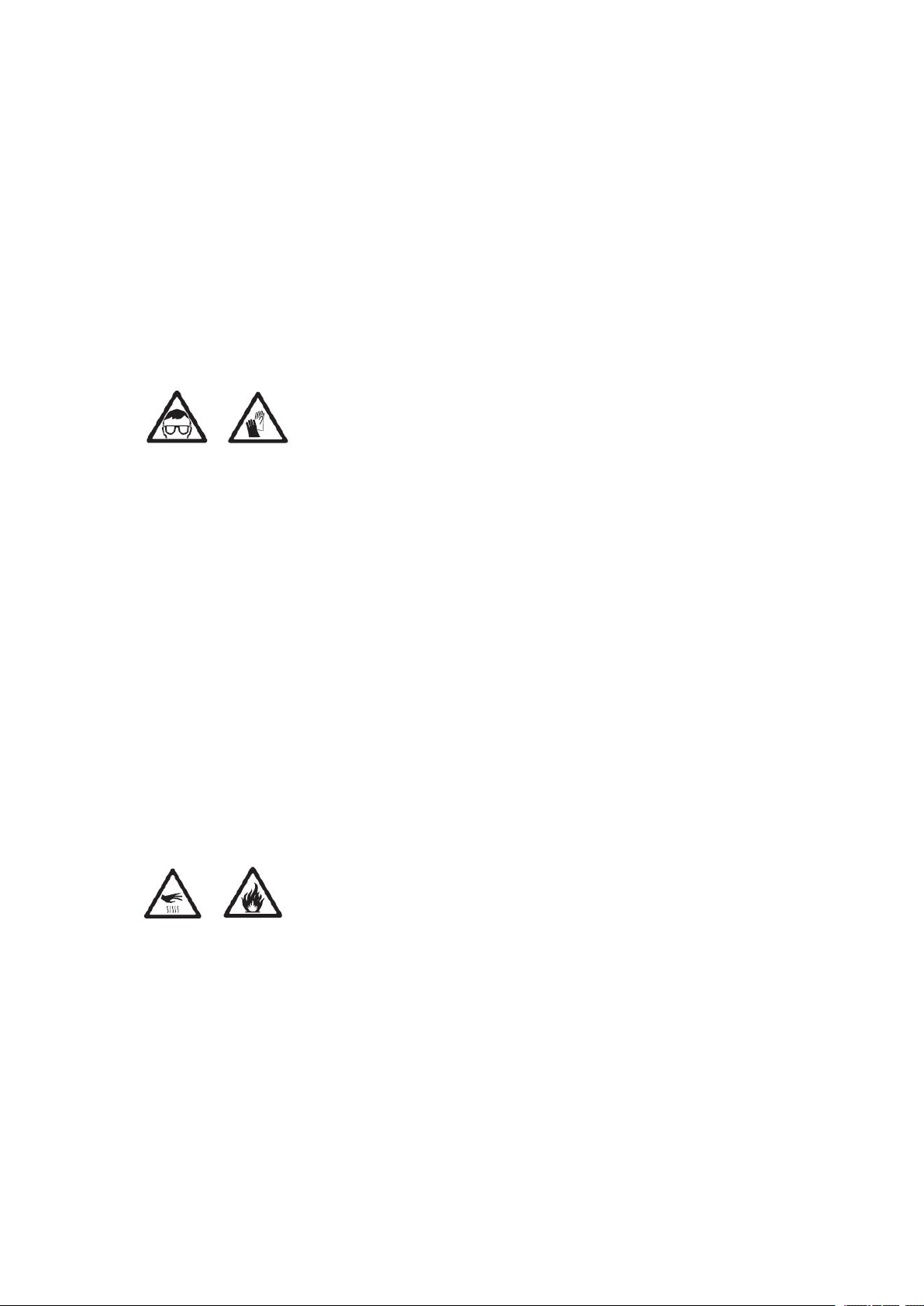
Lamp safe
It may cause burn damage to eyes and skin if unmask at the charging lamp, please
don’t stare at the charging lamp directly
Don’t use fixture with broken shell, resist-light board, shot lens, protector and
resist-heat board
Heat charging lamp with strong air pressure, may cause expression accidently
Maintain the light or change the lamp, protect-glasses and gloves are needed, cut off
the power supply and make sure the light is cool enough
Don’t use lamps of fragmentary, damaged or any other defects
Notice the using time and the status of the lamp, replace the lamp before the service
time marked in this manual or lamp manufacture limits
Lamp installed should fit for the relevant safe demands
Once the quartz part of the lamp broken, it will release static electricity and poison
gas. If the space is not large enough, please keep away and keep the space in good air
circulate. Wear protect gloves when clear up the broken lamp, don’t throw the useless
lamps, send the dangerous items to the relevant department
Be care of scalded and fire disaster
The temperature of light face may a bit high, please avoid to touch anybody or any
other items, keep it cool enough before moving it
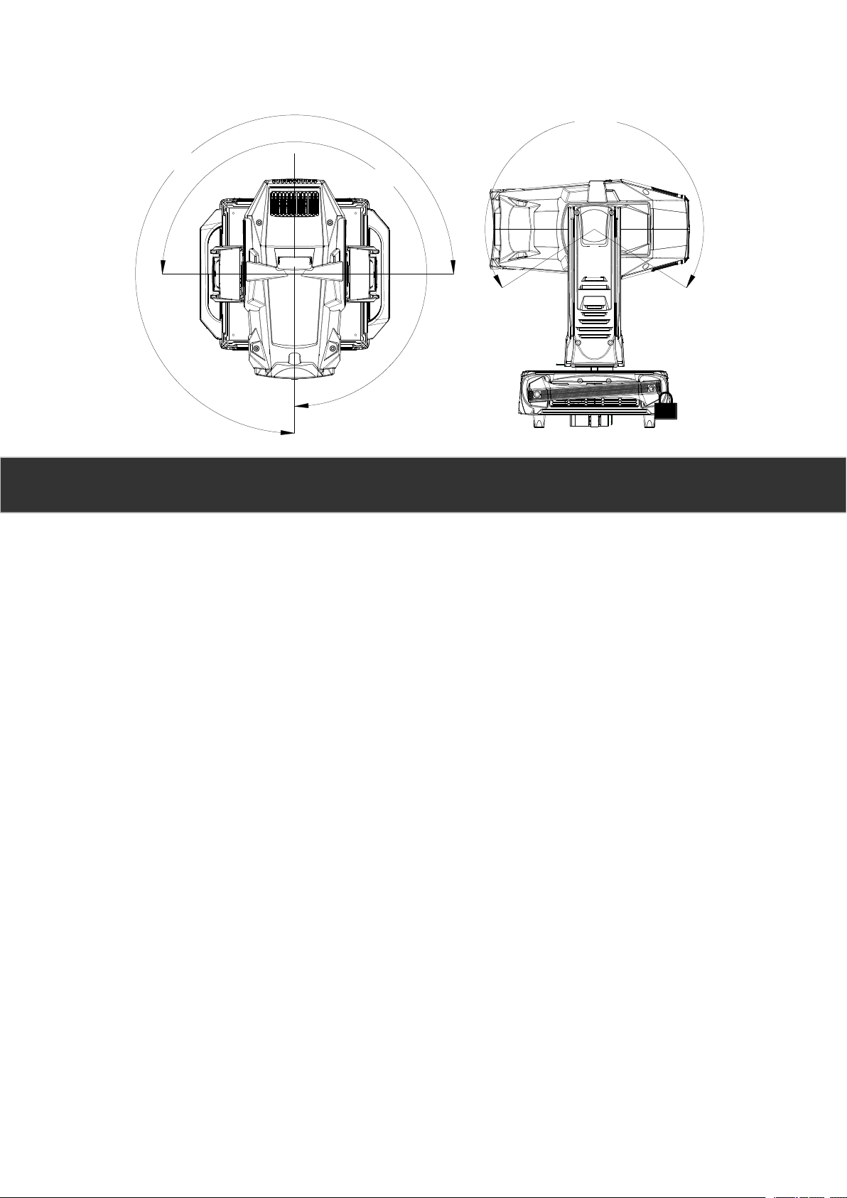
Keep away the combustible item (such as textile, wood, paper etc) from the light at
least 0.3 meters, inflammable items keep away from this item as far as possible, keep
0.1m space at least for in/out wind
Don’t light directly at façade of item with 4 meters
Covering the shot lens or rotate the shot lens to avoid the direct sunshine in day time
Don’t use the fixture when the temperate is over 40°C (104°F)
Prohibit to reinstall the fixture and install any parts original accessories from dealer,

6
prohibit to stick any paper of gobo on the lens and other parts, accessories admitted
by dealer only can used to change the light effect
Prohibit to control the fuse or temperate-control switch illegally, replace the fuse
according to the specified specification and load
Avoid fall injury
Don’t move the fixture alone
Install the light on flat ground or platform
Make sure the external accessories and holder stable enough stable platforms needed
when install, maintain and move the fixture, safe guard need Contact our after-service
for more information have not mentioned above
Declaration
Thanks for your purchasing our product. For in case of any possible injury, property loss
or product damege. Before you try out our product, please make sure you have read this
manual and understand all the safty guides, we will not afford any loss if users don’t follow
the safety guides.

7
2. Product introduction
2.1 Fixture dimensions
Unit: mm
328
408
268
487
123
719
330
555
492
114
138
230
412
2.2 Pan/Tilt Scan
270° 270°
245°

8
270° 270°
245°
3. Technical Feature
1.1 Power Supply
AC 100~240V 50/60Hz
1.2 Input Power
800W@220V
1.3 Lamp Source
Type: 680W LED lamp
Average Life: More than 20000 hours.
Light souce color: 6800K
1.4 Color System
One color wheel with 8 color filters.
1.5 Effects
2 gobo wheels, one wheel with 6 metal gobos. Other is a rotating gobo wheel,
with 7 interchangeable gobo filters. Gobo indexing, bidirectionally rotation and
with flowing and shaking effect.
1 Interchangeable 8-facet Prism
1 Separate flexible light mirror
Electronic strobe, 0-100% linear dimming, extremely smoothing for dimming
Electronic linear zoom 5°-45°

9
1.6 Control & Programming
Standard Mode: 39Channels, Simplified Mode: 34 Channels
DMX protocol signal: USITT DMX 512
Art-Net / RDM
Wireless DMX512
DMX signal connection: 3 and 5 pole XLR input and output
Pan/Tilt Resolution: 16 bit
Dimmer Resolution: 16 bit
1.7 Fixture Body
Two side handles for transportation
PAN and TILT lock for transport and maintenance
LCD Display, HMI user-friendly, Language: Chinese and English
1.8 Moving Feature
Angle:
- PAN = 540°
- TILT = 245°
Automatic autopositioning of PAN and TILT after accidental movement not
controlled by control unit
1.9 Electronics
Electronic control engine.
Fan speed control: Intelligently automatic fan speed adjustable.
Temperature electronic sensor detection.
LCD screen lighting information inquiry.
Up to GB7000.217-2008 standard and CE Certification
1.10 Weight
Net Weight: 32Kg

10
4. Function Introduction
1.11 Color wheel
Fixed Gobo Wheel
Rotate Gobo Wheel
Pos1 Pos2 Pos3 Pos4 Pos5

11
Pos6 Pos7
1.13 Profile system
4 independently steerable cutting blades, the cutting module can be rotated 90° overall.
1.14 CMY
With CMY Promise, you can get any color you want.

12
5. Transport
5.1 Items list
The light use flight case for package, every case has one light, and also have those
items as listed below:
Item name
QTY
UNIT
Warranty card
1
PCS
3 pole XLR signal cable
1
PCS
Safety Rigging
1
PCS
qualification certificate
1
PCS
User manual
1
PCS
5.2 Package & Unpackage
Unpacking the fixture
Remove the top of the flight case.
With one person on each side, lift the fixture out of the bottom of the flight
case.
Release the pan and tilt locks before operating.
Packing the fixture
Disconnect the fixture from power and allow it to cool.
Lock the head and yoke in the position shown in Figure 2.
Place the fixture in the bottom of the flight case. Place the top section over
the fixture without forcing.

13
6. Installation
6.1 Fixture Installation
Verify that the safety cable is undamaged and can bear at least 10 times the weight of
the fixture. Verify that the structure can bear at least 10 times the weight of all
installed fixtures, clamps, cables, auxiliary equipment, etc.
Bolt each clamp securely to a clamp bracket with an M12 bolt (grade 8.8 or better)
and lock nut.
Align a clamp with 2 mounting points in the base. Insert the fasteners into the base
and turn both levers a full 1/4-turn clockwise to lock. Install the second clamp.
If the truss can be lowered, fixtures can be clamped on directly from the double flight
case. If the fixture must be lifted, block access under the work area. Working safely
from a stable platform, hang the fixture on the truss with the arrow towards the area
to be illuminated. Tighten the rigging clamps.
Install a safety cable that can bear at least 10 times the weight of the fixture. The
attachment point is designed to fit a carabiner clamp.
The minimum space between fixtures in array is 900mm.

14
7. Data Link
7.1 Pin Define
The fixture use 3-pin XLR cable for DMX input and output. Use a cable conforming
to specifications EIA RS-485: 2-pole twisted, shielded.
Pin 1
Shield
Pin 2
Signal –
Pin 3
Signal +
7.2 Data connect
Connect the DMX data input from the controller to the light 3-pin input (male)
socket.
Using the sockets that match your data cable, connect the output of the fixture closest
to the controller to the input of the next fixture.
Insert a male 120 Ω XLR termination plug in the 3-pin or 5-pin output of the last
fixture on the link.
7.3 Signal Reliability Hints
Use shielded twisted-pair cable designed for RS-485 devices: standard microphone
cable cannot transmit control data reliably over long runs. 24 AWG cable is suitable
for runs up to 300 meters (1000 ft). Heavier gauge cable and/or an amplifier is
recommended for longer runs.
Never use both outputs to split the link. To split the serial link into branches use a
splitter .
Do not overload the link. Up to 32 devices may be connected on a serial link.
Terminate the link by installing a termination plug in the output socket of the last
fixture. The termination plug, which is a male XLR plug with a 120 ohm, 0.25 watt
resistor soldered between pins 2 and 3, “soaks up” the control signal so it does not

15
reflect and cause interference. If a splitter is used, terminate each branch of the link.
This fixtures introduced before 1997 have reversed polarity data sockets (pin 2 hot
and pin 3 cold). The socket polarity is labelled. Use a phase-reversing cable between
any device with reversed polarity.
8. AC Power Supply
8.1 Fuses
The fixture is equipped with auto-switching power supply that automatically adjusts to
any 50-60Hz AC power source from 200-240 Volts. The fixture is protected by one 2 A
blow primary fuse (φ5x20).
8.2 Power connection
You may need to install a cord cap that fits your supply on the power cable. A 3-prong
grounding-type plug must be installed following the manufacturer’s instructions. The
table shows some possible pin identification schemes; if the pins are not clearly identified,
or if you have any doubts about proper installation, consult a qualified electrician.
To apply power, set the power switch on the base to the “On” position.
8.3 Replace Power Cable
Notice:
For protection from electric shock, the fixture must be earthed!

16
1. Tear down the former power cable
2. Tailor a cable with specification of 3 meters long and 3*2.5 square meters
3. Wiping off the protect skin as the picture above, across the plug cover and chuck
4. Make sure the cable at the correct position and press tightly. L-brown N-Blue
–Yellow/Green
5. Installing the plug and roll the cover tightly
6. Connecting appropriate ground touch 3 pins plug to the other side
9. DMX Channels
XL600
39CH
Mode1
34CH
Mode2
DMX
Value
Function
Dimmer
1
1
0---255
Brightness--->Darkness
Dimmer FINE
2
0---255
Strobe
3
2
0---3
4---103
104---107
108---207
208---212
213---225
226---238
239---251
252---255
Closed
Slow Strobe--->Fast Strobe
Open
SlowPuls---->Fast Puls
Open
Random Slow Strobe
Random Medium Strobe
Random Fast Strobe
Open
Color
4
3
Cyan
5
4
0---255
EXCLUDED---->INSERTED
Magenta
6
5
0---255
EXCLUDED---->INSERTED
Yellow
7
6
0---255
EXCLUDED---->INSERTED
CTC
8
7
0---255
EXCLUDED---->INSERTED
Macro Color
9
0---255
IRIS
10
8
0---128
129---131
132---171
172---211
212---251
252---255
MAX----->MIN
Close
Slow Puls---->Fast Puls
Slow Puls Fast Close---->Fast Puls
Fast Close
Slow Puls Fast Open---->Fast Puls
Fast Open
Open

17
Gobo1 Select
11
9
Gobo1 Index Rotation
12
10
0---127
128---191
192---255
0°---->360°(FINE IN 13CH)
CW Rotating Slow---Fast
CCW Rotation Fast---Slow
Gobo1 Index Rotation
FINE
13
0---255
Fixed Gobo
14
11
0---4
5---10
11---16
17---22
23---28
29---34
35---40
41---46
47---52
53---58
59---74
75---90
91---106
107---122
123---138
139---154
155---170
171--- 186
187--- 202
203---229
230---255
White
Gobo1
Gobo2
Gobo3
Gobo4
Gobo5
Gobo6
Gobo1Shake Slow--->-Fast
Gobo2 Shake Slow--->-Fast
Gobo3 Shake Slow---->Fast
Gobo4 Shake Slow---->Fast
Gobo5Shake Slow---->Fast
Gobo6 Shake Slow---->Fast
Gobo7 Shake Slow---->Fast
Gobo8 Shake Slow---->Fast
Gobo9 Shake Slow---->Fast
CW Rotation Slow--->Fast
CCW Rotation Fast--->Slow
BLADE1
15
12
0---255
EXCLUDED---->INSERTED
BLADE2
16
13
0---255
EXCLUDED---->INSERTED
BLADE3
17
14
0---255
EXCLUDED---->INSERTED
BLADE4
18
15
0---255
EXCLUDED---->INSERTED
BLADE5
19
16
0---255
EXCLUDED---->INSERTED
BLADE6
20
17
0---255
EXCLUDED---->INSERTED
BLADE7
21
18
0---255
EXCLUDED---->INSERTED
BLADE8
22
19
0---255
EXCLUDED---->INSERTED
FRAMING ROTATION
23
20
0---255
Position 0°---->90°
Animation
24
21
0---10
11----133
134---255
White
CW Rotation Fast--->Slow
CCW Rotation Slow--->Fast
Prism1
25
22
0---127
128---255
EXCLUDED
INSERTED
PrismRotation1
26
23
0---127
128---190
191---194
Position 0°-->360°
CW Rotation Fast---> Slow
STOP

18
195---255
CCW Rotation Slow--->Fast
FORST
27
24
0---127
128---255
EXCLUDED
INSERTED
NULL
28
25
Focus
29
26
0---255
Focus FINE
30
0---255
Zoom
31
27
0---255
Zoom FINE
32
0---255
PAN(X)
33
28
0---255
PAN(X) FINE
34
29
0---255
TILTE(Y)
35
30
0---255
TILTE(Y) FINE
36
31
0---255
P/T SPEED
37
32
0---128
129---170
171---211
212---255
Fastest------->Slowest
SlowSpeed (1/3 MaxSpeed)
MediumSpeed (1/2 MaxSpeed)
Fast Speed (Fastest Speed)
NULL
38
33
Control
39
34
0---127
128---153
154---179
180---205
206---231
232---255
Undefined
Undefined
Undefined
Undefined
Undefined
Reset ALL( > 3s)
10. Maintenance
12.1 Cleaning
The Light requires routine cleaning. The schedule depends heavily on the operating
environment; please consult a service technician for recommendations.
Refer all service not described here to a qualified technician.
Use care when cleaning optical components and work in a clean, well lit area. The
Warning!
Disconnect the fixture from power before removing any cover.
Important!
Excessive dust, smoke fluid, and particulate buildup degrades
performance and causes overheating and damage to the fixture that is
not covered by the warranty.

19
coated surfaces are fragile and easily scratched. Do not use solvents that can damage
plastic or painted surfaces.
Inspect the air filters regularly and clean before they become clogged. Replace the air
filters with new ones when replacing the lamp.
To maintain adequate cooling, dust must be cleaned from the fans and air vents
periodically.
12.2 Cleaning optical components
Disconnect the fixture from power and allow the components to cool completely.
Remove the head cover.
Vacuum or gently blow away dust and loose particles with compressed air.
Remove stuck particles with an unscented tissue or cotton swab moistened with glass
cleaner or distilled water. Do not rub the surface: lift the particles off with a soft
repeated press.
Remove smoke and other residues with cotton swabs or unscented tissues moistened
with isopropyl alcohol. A commercial glass cleaner may be used, but residues must be
removed with distilled water. Clean with a slow circular motion from center to edge.
Dry with a clean, soft and lint-free cloth or compressed air.
12.3 Cleaning the fan and air vents
Remove dust from the fans and air vents with a soft brush, cotton swab, vacuum, or
compressed ai
Table of contents
Popular Light Fixture manuals by other brands

LDPI
LDPI LEXF Installation, operation and maintenance instructions

Clas Ohlson
Clas Ohlson SOL-004 instruction manual

NORDRIDE
NORDRIDE 4040 VISION 360 operating instructions

Kichler Lighting
Kichler Lighting RICO 37538 instructions

Broncolor
Broncolor Minicom 40 operating instructions

Brant Radiant Heaters
Brant Radiant Heaters LR-LB1 Series Installation, operation and maintenance manual