9
Overview
The Razorweld TIG320RZ ACDC is a complete and professional TIG /MMA welding machine that is ideal for all high-end aluminium,
stainless steel fabrication, marine and industrial engineering welding situations.
in compliance to AS/NZ60974-1.
AC TIG: Featuring multiple AC output wave forms of Square, Trapezoidal and Sine, combined with AC Balance and AC Frequency control
you have the ultimate tool in AC TIG Welding mode to suit all your AC TIG welding requirements.
DC TIG: Latest 43KHz inverter frequency technology provides the ulitmate in smooth and stable arc condition for DC TIG welding mode,
coupled with the Digital Weld Sequence Program provides complete and professional DC TIG Welding function.
MIX ARC: This function of MIX AC/DC makes it possible to modulate the welding current, alternating a period of TIG AC with a period
higher welding speeds and establishing the weld puddle quicker on cold workpieces. The operator adjustable parameter is the percent-
age of AC waveform compared to DC- waveform over the entire period, which can be varied from 5~95%.
MMA: Full attention is given to MMA welding providing both DC and AC output modes. Ignition AMP and Ignition Time provides for an
operator controlled Hot Start of the weld by applying extra current to the set weld current over a preset time.Arc force allows adjustment of
ideal arc condition no matter what the electrode and welding situation.
Weld Sequence Control: The Digital Weld Sequence Program and intelligent MCU software provides full TIG functionality inAC, DC and
MIX modes. Adjustable pre-sets include Pre-Gas time, Start Current, Up Slope, Down Slope, Finish Current level and Post-Gas time.
Digital Pulse parameter pre-sets include Peak & Base current; Pulse Frequency & Pulse Width. HF and LIFTArc Ignition.
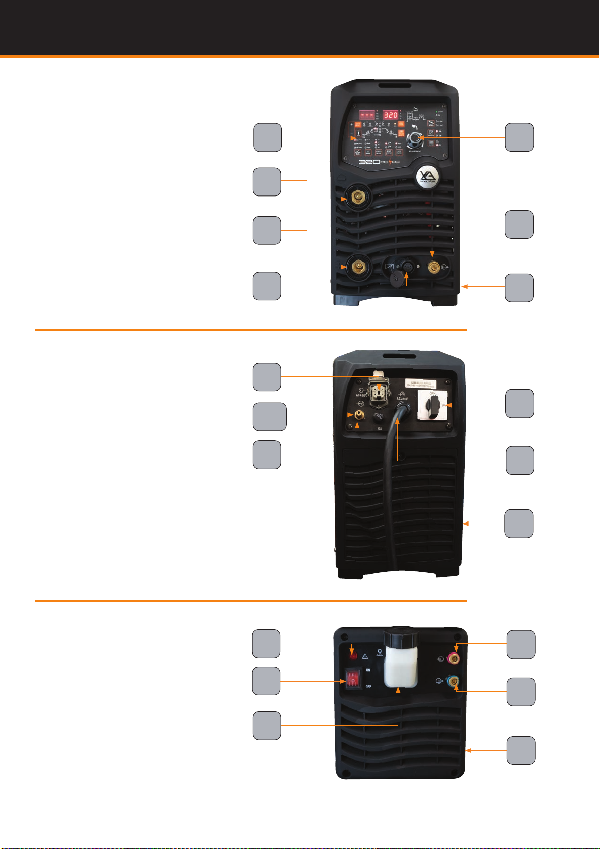
Torch Mode:
Remote Control: The Remote Interface allows connection of either Torch Remote or Foot Pedal for remote control of amperage output.
Job Memory: Job memory function allows you to enter and store weld parameter settings under job numbers. The job number can be
recalled to reveal and use the weld parameters stored, weld parameters can be further adjusted and stored as required. A total of 50 Jobs
can be memorised and stored for recall.
Water Cooler Control: Activating the water cooler control allows for the water cooler to operate when welding current is available during
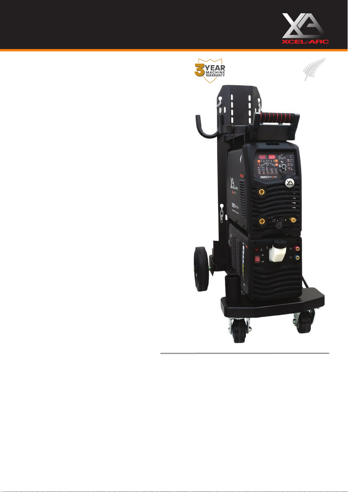
RAZORWELD TIG320RZ AC/DC
TIG/MMA - 320 Amp AC/DC Inverter Welder
Welds:Aluminium, Magnesium, Zinc Alloys, Steels, Stainless, Cast Iron, Bronze, Copper
Razor
W
eld
Product Code: XA-TIG320RZACDC-K
Standard Package includes: TIG320RZACDC Machine, ARC T4W X 4m Tig Torch, Earth Lead & Arc Lead 35mm x 4m, Argon Regulator
AC MIX ARC: This function of MIX AC/DC makes it possible to modulate the welding current,
TIG welding can be combined with the high penetration of DC TIG welding, obtaining higher
welding speeds and establishing the weld puddle quicker on cold workpieces. The operator
adjustable parameter is the percentage of AC waveform compared to DC- waveform over the
entire period, which can be varied from 5~95%. Ideal for welding heavier gauge material with
less current than AC welding.
AC Square Wave: Allows the current to change from electrode + positive to electrode - nega-
tive very quickly. This produces high voltage as the current switches polarities allowing the
arc to restart easily. The arc can be maintained without the use of high-frequency and the fast
transitions provide for responsive, dynamic and focused arc for better directional control.
AC Triangle Wave: Characterised by a particularly soft and concentrated arc combining the
effect of peak amperage while reducing overall heat input. Leads to quick puddle formation
and, because of lowered heat input, reduced weld distortion, especially on thin material This
wave form is ideal for very precise welding of thin Aluminum plate.
AC Sine Wave: It is the standard Wave form, characterised by low noise and excellent arc
control, it also gives the soft-arc feel of a conventional power source, while using square tran-
sitions to eliminate the need for continuous HF.
AC WAVE FORMS