5INSTALLATION GUIDE FEELGOOD SHOWER UV/IR V4
INSTALLATION
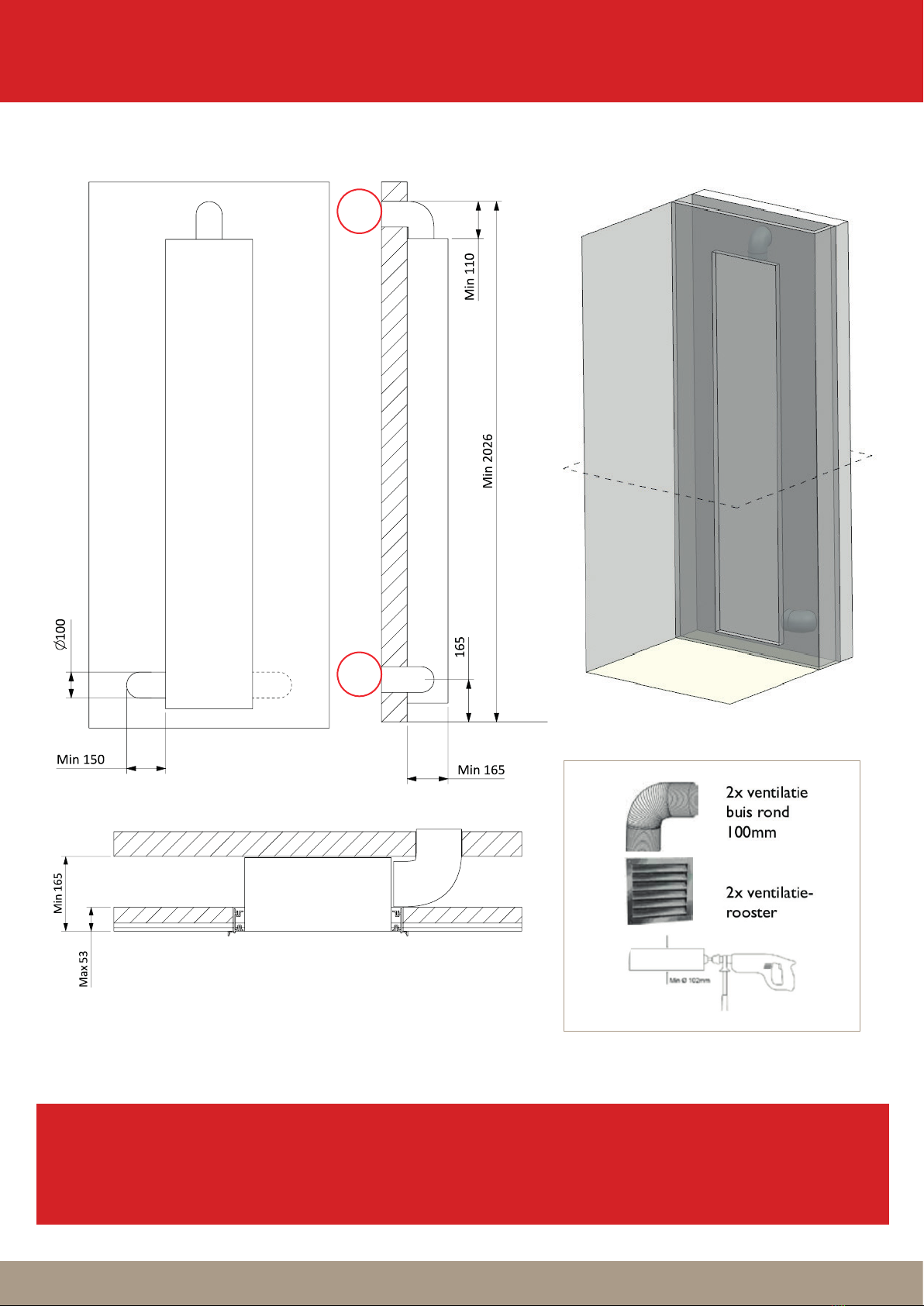
1. DIMENSIONING
For this installation round flexible ventilation pipers are used, and the aluminium rectangle profile is placed on top of the
tiles. Condition for this installation is that de tickness of the wall is no more as 53mm.
• e electrical installation can only be carried out by a specialised company, observing the legal guidelines and the
national requirements concerning the installation, for example, in the Netherlands NEN 1010 and international IEC
60364-7-701.
• e Feelgood shower UV/IR is an approved quality product and meets the CE guidelines. For the correct operation of
this product the user manual must be adhered
• e Feelgood shower UV/IR has a maximum capacity of 2060 W. Do not connect other heavy electrical equipment to
the same fuse group next to the Feelgood shower. e unit must be connected to a fuse group which is secured with
a circuit breaker of 16A.
• Make sure to connect a double pole switch between the fuse group and the Feel good shower which can be turned
o manually at any time.
• Check whether the voltage (230 V) corresponds with the local mains voltage before you connect the unit.
All dimensions in mm.
250-400