Xilin BFC6-8 Installer manual

BFC6-7/BFC6-8
Scale pallet truck
Operation manual
Spare parts catalogue
200
9
-
09

1
Welcome to choose the BFC6 hand pallet truck with scale. Please read this
operation manual carefully efore you use it. The manual could provide direct
help for your operation.
Hint:
The BFC6 hand pallet truck with scale is only used to weigh up the pallet
cargos at storehouse. This kind of truck possesses the features of sta le
lifting, easy operation, safety & relia ility and so on. And it is suita le to e
operated indoor on level and hard ground. Meanwhile it can also e used as
a transportation tool.
Note:
This type of hand pallet truck with scale adopts lead-acid storage attery,
so it can not e in the state of lack of electricity for a long time. Pay
attention to in-time charge of the storage attery, otherwise it will cause
damage to the attery.
1.
..
.Main tec nique indexes
Max weighing:2000Kg
Division value:1kg/0.5kg
Output format:multiple row print (gross weight, tare weigh and net weight)
2.
..
.Assembly of t e and pallet truck wit scale
2.1 Assem ly of hand grip
2.1.1 See the fig 1. Dismantle the spring pin 1 from pin roll 2, and then pull out the pin roll
2.
Fig.1 Fig.2
2.1.2 Insert the hand grip 3 to place A. Couple the hand grip 3 and pump ody 4 with pin
roll 2. In the portrait direction, the pin roll 2 should not e mounted to the end, and
put apart some place to turn freely.
2.1.3 Turn the pin roll 2, and make sure that the ig hole axis of pin roll is just in the
verticality. Put the chain 5 of hand grip get across the middle hole of pin roll 2. See
fig 2.
2.1.4 Take screw nut which is at the end of chain 5 and hitch the groove of lever oard 6.

2
See fig 2 and fig 5.
2.1.5 Turn the pin roll 2 to the original position, and push longitudinally to the end. Then
put spring pin 1 get across pin roll 2 to reset.
2.1.6 See fig 3, turn the hand grip to the level position, pull out pin 7 and save pin 7 with
care for next use.
Fig. 3 Fig. 5
2.1.7 Try to rock the hand grip and operate different positions of control handle kno 8 to
examine the lifting, free position and dropping and check that whether the different
positions are normal or not. See fig 4
2.1.8 The screw 9 in fig 5 is used to adjust the truck situation. When the truck ody drops
immediately after it is lifted, you should
turn the screw 9 a little counter
-clockwise. And then try the truck again
until truck ody could lift normally. If the
truck ody couldn’t drop after it is lifted,
you should turn the screw 9 a little
clockwise. And then try to operate truck
again until the truck ody could drop
normally. The external hexagon nut 10 at
screw 9 plays the locking function in the
truck. So you should undo the external
hexagon nut 10 efore adjustment. And
screw down the nut 10 after you finish
the adjustment.
2.2 Instrument installation
2.2.1 Steelyard stand should e placed as
indicated in fig6 and align the fixed
holes. Fig. 6
2.2.2 Use three screws 11 to fix the steelyard stand as shown in fig 6.
Fig. 4

3
3. Operation in using:
::
:
3.1 On /Off key
3.2 Zero
O
3.3 Tare
T
3.4 Print
3.5 Switching Unit
F
Click keys, instrument units kg and l can e switched etween the loop
4. Ot er operations:
4.1 See printer instruction for the details of printer operation.
4.2 See instrument instruction for other operations of the instrument.
5. Loading type and rated weig t
5.1 The est loading type is that the gravity center of the cargo is just in the middle of truck
forks. The rated weight must e reduced when the cargo gravity center is not in the
middle of truck forks. The rated weight is shown as the la el.
5.2 See fig 4. When the hand pallet truck with scale is used to weigh or carry some cargo,
In “power off ”state, hold the key 2 seconds and all display segments will
light. In normal display state, hold this key 2 seconds, the instrument will
show [-OFF- ], then power off.
Zero the scale.
Tare the scale, the display will change to net mode.
Print the current weight.

4
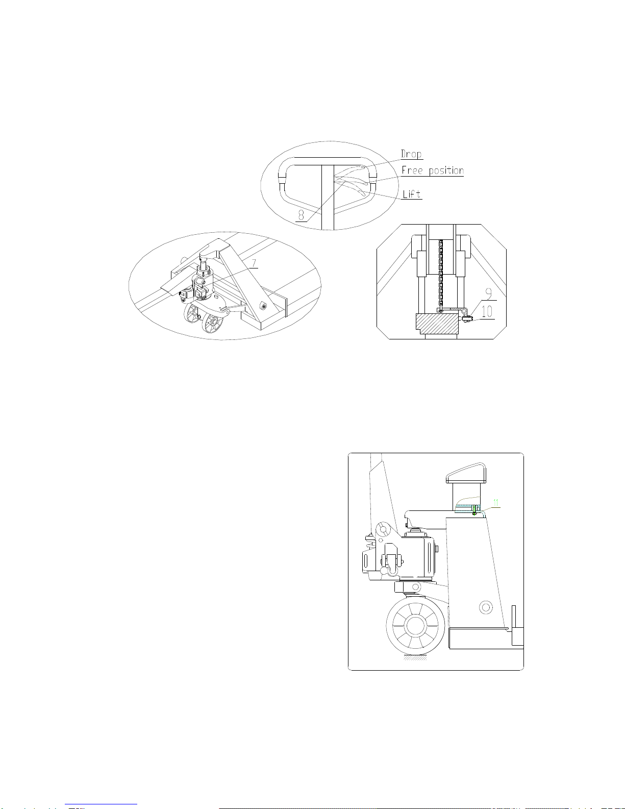
the handle kno 8 should e placed on dropping condition to let the truck forks down
to a certain position. Then insert the forks to the pallet and place the handle kno 8 on
the lifting condition so as to rock the hand grip to lift the truck forks.
5.3 During the process of moving cargo, the handle kno 8 should e placed on the free
position.
6. Oil
6.1 The oil capacity which oil pump needs is a out 250ml (or 0.25kg). According to the ISO
oil criterion, the choice of oil is 32# when the environment temperature during
-5~40℃.The choice of oil is low temperature oil when the environment temperature
during -35~-5℃.
6.2 Disposal of waste oil: Dispose the waste oil in terms of relative laws and for id pouring
out anywhere.
7. Maintenance
The routine check should e carried out daily and every a normal phenomenon should e
dealt with immediately. Please do not use faulty truck in order to prolong the service life. All
the rotary joints should renew the motor oil every three months. Especially pay more
attention to the place etween wheel and axis. Make sure that there is not any yarn or
other rags in order to keep all wheels running with handiness. Make sure the electric power
is full, instrument display and printing is in working condition. If the hand pallet truck with
scale has not een used for a long time, the attery should e removed and the quantity of
electricity should e enough all the time.
8. Working environment conditions
This type of hand pallet truck with scale is applica le to ordinary industrial environments
and usiness environments. The operating temperature is in the range of -5℃~+40℃. The
requirement of relative humidity is 10-95%RH. The working place must e plane. This type
of hand pallet truck with scale is not suita le to e used in the special place where there are
some explosive materials.
9. Warning level A
9.1 Please read the operation instruction carefully efore you operate the hand pallet truck
with scale and learn a out all the features of this type of hand pallet truck with scale.
9.2 If you want to let the cargo down y controlling the hand grip, you should lift the truck
forks a little at first, and then let the truck down slowly. It is for idden to pull the
handle kno with great force, ecause rapid dropping could cause some damages to
oth the hand pallet truck with scale and cargo.
9.3 Don’t rock the hand grip at a high speed and in a high frequency.

5
9.4 Don’t load the cargo at a high speed.
9.5 Do not overload the forks. Overloading could keep the hand pallet truck with scale
from working normally.
9.6 The gravity center of cargo should e in the middle of truck forks. The offset of cargo
could make the truck out of alance.
9.7 Non-palletized cargo should not e weighed y this type of hand pallet truck with scale.
9.8 Do not put the cargo on the truck forks for a long time.
9.9 When hand pallet truck with scale does not work, make sure that the truck forks is on
the lowest position and the power should e cut off.
9.10 Do not load people and let them stand on the truck forks and slide. It is strictly
for idden that put any part of ody elow the cargo.
9.11 The hand pallet truck with scale should e operated on flat and hard ground and don’t
use it on the slope!
9.12 Do not use the hand pallet truck with scale in environment exposed to rain and sun.
9.13 Do not operate the unspecified position.
9.14 Do not try to repair the hand pallet truck with scale unless you have een trained.
9.15 The power used for the printer is free-maintenance charged attery. Once the attery
is damaged or has een used up, it should e carried to recycle ins and for id
disposing anywhere.
9.16 This type of hand pallet truck with scale is not suita le for trade settlement.
10. T e requirements of oisting and transportation
10.1 See Fig 10, oth of hand grip and steelyard stand should e detached and packed in
another way efore hoisting and transportation.
10.2 The hand grip and steelyard stand should e fixed sta ly in case of gliding and
damages. And then they are packed in a case and transported y forklift truck or
hoisting apparatus.

6
BFD6-7/8 andle assmbly and spare parts list
No.
Drawing no.
Description Qty.
No.
Drawing no. Description Qty.
1 DF.1-01a Location plate 1 9 GB879-86 Pin 3x20 1
2 GB879-86 Pin 4x30 2 10
CN.2-13 Pressure roller 1
3 DF.1-02 Roller 1 11
CSB10 Bushing 1220 1
4 GB879-86 Pin 4x20 2 12
DF.1.2-00 Pull rod 1
5 GB879-86 Pin 6x30 1 13
SF-1 Bushing SF-1F2015
2
6 DF.1-03 Handle kno 1 14
Chain C-6-9-04A 1
7 BF.1.1-00 Handle assem ly
1 15
GB889-86 Lock nut M5 1
8 DFⅠ.2-04 Pin 1
BFD6-7/8 pump assmbly and spare parts list

7

8
No. Drawing no. Description Qty. Remark
1 BF.2-1 Pump plunger 18x97 1
2 AF.2-3 Spring cap 1
3 BF.2-6a Spring 1
4 DH20 Dust ring 18 1
5 UHS20 Y-ring 18 1
6 AM-19 Shaft 1
7 JF.1-17 Seal screw M20x1.5 1
8 JB982-77 Com ined washer 20 2
9 AF.2-9 Spring 1
10 SYBC2-07 Valve core 1
11 SYBC.2-08 Valve 1
12 GB308-77 Steel all 6.35 1
13 BF.2.1-00 Pump house 1
14 GB894.1-86 Axile snap ring 8 1
15 GB308-77 Steel all 5 1
16 CN.2-26 Steel all ase 1
17 CN.2-27 Spring 2x8x16 1
18 CN.2-28 Adjusted screw M10x1 1
19 JB982-77 Com ined washer 10 2
20 CN.2-17 Screw M10x1 2
21 BF.2-5 Spring 1.2x9x22 1
22 AF.2-7 Firing pin 1
23 GB3452.1-82 O-ring 7X1.8 1
24 AF.2-06a Firing pin ase 1
25 GB3452.1-82 O-ring 8x2.65 1
26 GB73-85 Lock screw M6x25 1
27 GB6170-86 Hux nut M6 1
28 AF.2-08 Lever plate 1 Standard
AF.2-08Ⅲ Lever plate 3 1 Pedal
29 BF.2-3 Shaft 8x58 1
30 UHS31.5 Y-ring 31.5 1
31 GB3452.1-82 O-ring 65x2.65 1
32 BF.2-2a Guide sleeve 31.5 1
33 GB3452.1-82 O-ring 31.5x3.55 1
34 DH31.5 Dust ring 31.5 1
35 AF.2-4 Piston rod 31.5x263 1
36 GB308-77 Steel all 19.05 1

9
BFC6-7/8 Final assembly drawing and spare parts list

10
Qty
2
2
1
4
4
8
4
1
4
1
1
1
3
1
1
2
Description
Roller
Lock nut
M6
Scale pan unit
Support plate
Fork wheel
60X70
Spring pin shaft
5X28
Pin shaft with
two
hole
Lid
Pan head screw
M6X8
Clip for attery
Battery
Meter
(print)
Inner hexagon
olt M6X16
Printer
Pressure
wheel
axle
20X106
Spring pin
5X40
Meter
Drawing no
AF
-09
GB889
-86
BFC6.3
-00
DFQ
-03
DFQ
-01A/B
GB879
-86
DFQ
-02
BFC6
-03
GB67
-85
BFCD7.2.1
-03
3
-FM-10
GB70
-85
BF
-01
GB879
-86
No
39
40
41
42
43
44
45
46
47
48
49
50
51
52
53
54
55
Qty
4
2
1
2
1
1
4
8
4
4
4
2
2
2
2
2
2
2
2
Description
Circlip for shaft
16
Connecting rod
Long shaft
Circliip for hole
25
Inner hexagon
olt
M6X12
Fork frame
Senso
Inner hexagon
olt
M12X30/4
0
Lock nut
M10
Spring pin
5X30
Spring pin
5X22
Pin shaft with
two
ho
le
16X111
Pin shaft with
two
ho
le
16X148
Wheel fra
me
Pin shaft with
hole
Spring pin shaft
5X28
Fork wheel
70X80
Hexagon olt
M6X50
Sleeve
Drawing no
GB894.1
-86
BFC6.2.1
-00
AF
-02
GB893
-86
GB70
-85
BFC6.1
-00
BFC6
-01
GB70
-85
GB889
-86
GB879
-86
GB879
-86
BFC6.2
-02
DB.3.3
-04
BFC6.2
-01
DFQ
-05
GB879
-86
DFQ
-04A/B
GB5782
-86
AF
-08
No
20
21
22
23
24
25
26
27
28
29
30
31
32
33
34
35
36
37
38
Qty
1
1
1
1
1
1
1
1
2
2
8/12
4
2
2
2
1
2
2
2
Description
Handle assem ly
Oil pump
assem ly
Locknut M8
Axle, front wheel
Hexagon olt
M8X55
Bearing
8111
Support seat
Circlip for
shaft
55
Spring pin
5X28
Wheel
160X50
Bearing
60204
Semi
-circular ring
Bowl washer
Circlip for shaft
20
Dustproof cover
Rocker arm unit
Pin roll
16X40
Coupling joint
Dou le
-
groove
pin roll
16X52
Drawing no
BF.1
-00
BF.2
-00
GB889
-86
AF
-07
GB5782
-86
GB306
-64
BF
-03
GB894.1
-86
GB879
-86
DFQ.4
-01
GB278
-64
AF
-05
AF
-06
GB894.1
-86
DF
-10
BF.3
-00
BF
-04
AF.7
-05
EF
-01
No
1
2
3
4
5
6
7
8
9
10
11
12
13
14
15
16
17
18
19

11
This manual suits for next models
1
Table of contents
Popular Scale manuals by other brands

Life Smart
Life Smart LS-936 user manual

digi-tech
digi-tech QM7231 instruction manual

Silvercrest
Silvercrest 281168 Operation and safety notes

eatsmart
eatsmart Precision GetFit ESBS-06 user guide

Silvercrest
Silvercrest 298770 Operation and safety notes

Silvercrest
Silvercrest HG01696A Operation and safety notes