Teledyne Lecroy PCI Express 5.0 x16 Slot Interposer User manual

PCI Express®5.0 x16 Slot Interposer
User Manual and Quick Start Guide
Components
The interposer package includes the following components:
• PCI Express 5.0 x16 Slot Interposer
• Half height bracket
• Four spare screws for bracket attachment
• DC Power Adapter (12V @ 8.5Amps)
• User Manual and Quick Start Guide (this document)
Inspect the received shipping container for any damage. Unpack the container and account for each of the system
components listed on the accompanying packing list. Visually inspect each component for absence of damage.
In the event of damage, notify the shipper and Teledyne LeCroy. Retain all shipping materials for shipper’s inspection.
Introduction
Use this document for quick installation and setup.
The Teledyne LeCroy PCI Express 5.0 x16 Slot Interposer plugs in to a PCIe®CEM Connector and allows you to probe PCI
Express traffic between a host and a PCIe expansion card. The interposer assures reliable data transmission while providing
100% capture of all data traffic flowing through the PCIe slot interface. Connecting the interposer to a Teledyne LeCroy
analyzer allows decoding and display of data flowing in both directions and across all lanes, and will display data traffic using
the industry-standard CATC Trace™ data display, along with a wide range of traffic and error reports. The Gen5 x16
Interposer is for use with a Summit T5 Gen5 capable analyzer. The interposer uses Teledyne LeCroy’s T.A.P.5 technology
to ensure complete data capture at Gen5 rates with minimal signal perturbation.
The Gen5 Interposer supports data rates of 2.5 GT/s, 5.0 GT/s, 8.0 GT/s, 16.0 GT/s and 32.0 GT/s, and link width up to x16.
The PCIe connector on the top of the card will support PCIe expansion cards up to x16.
PCI Express 5.0 x16 Slot Interposer
1
2

Gen5 to Gen5 x8 Y Cable for Summit T5
This cable allows recording for up to x8 links at up to 32.0 GT/s with single Summit T516 and a Gen5 x16 CEM Interposer.
See Summit T516 Analyzer documentation for connectivity and configuration details.
Gen5 to Gen5 x8 Y Cable for Summit T5 (PE028UCA-X)
A
B
3

4
Connections
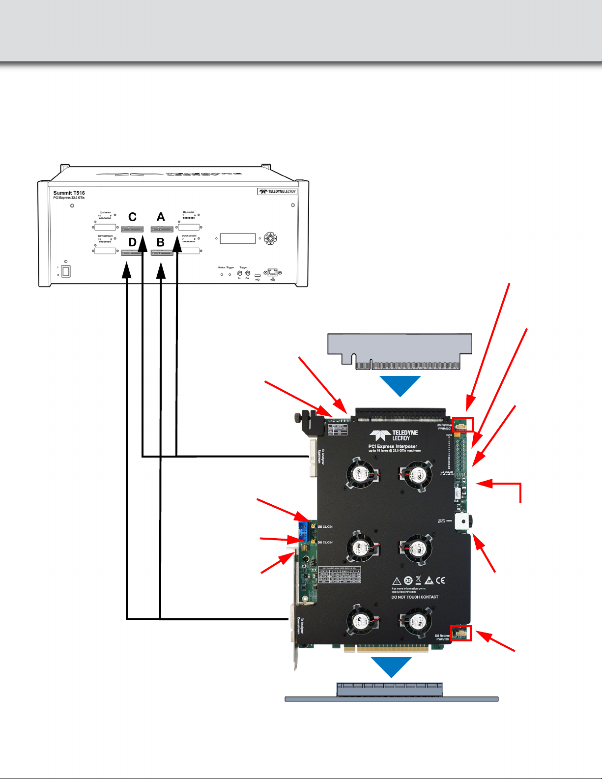
Perform the following steps to connect the Interposer (see the image below):
Warning: The interposer has a bracket that can be secured to a chassis to provide stability. Always secure the
interposer properly to a chassis otherwise the interposer (and your equipment) could be damaged and
warranties void.
Warning: Handle interposer with care and grab it from the bracket, top connector or sides of the board. Avoid
touching the components or the surface of the PCB when installing or un-installing the interposer.
1. Install the Interposer into the host system under test PCIe CEM slot connector.
2. Secure the interposer to the host chassis using a screw.
3. Secure the DUT using the clamp as described in Section “6”.
4. Install the PCIe expansion card under test (DUT) into the top connector on the interposer.
5. Connect the 12V @ 9A DC power adapter supplied with the interposer. Make sure that the DC Power adapter is
turned on.
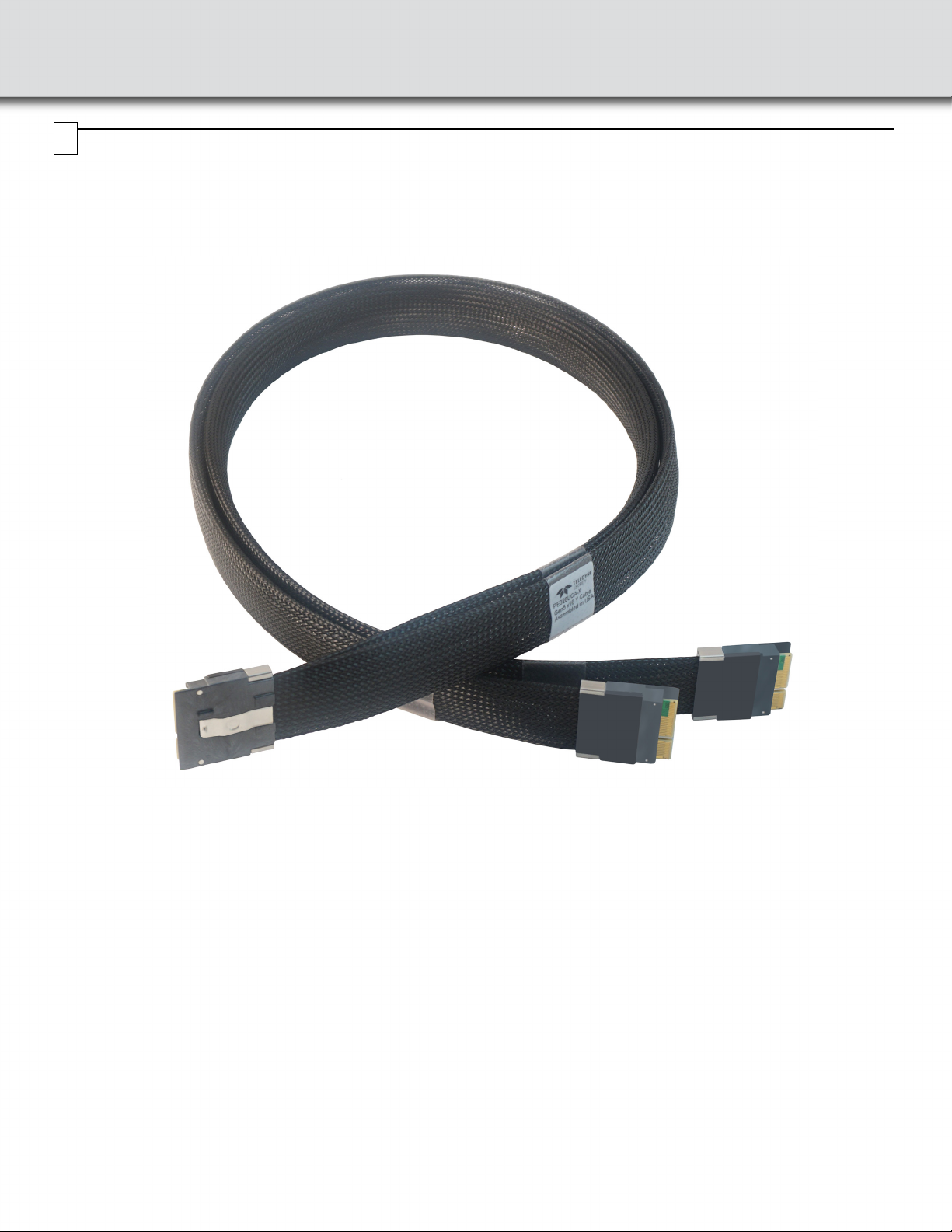
6. Connect the first Gen5 to Gen5 x8 Y cable (PE028UCA-X) to the DS[0:15] connector on the interposer.
See PCIe Gen5 Cables User Manual and Quick Start Guide.
a. Connect the cable connector labeled B to the connector B on the Summit T516.
b. Connect the cable connector labeled A to the connector D on the Summit T516.
7. Connect the second Gen5 to Gen5 x8 Y cable (PE028UCA-X) to the US[0:15] connector on the interposer.
a. Connect the cable connector labeled B to the connector A on the Summit T516.
b. Connect the cable connector labeled A to the connector C on the Summit T516.
8. Use the lane width control button SW3 (see Section “5”) to match the minimum physical lane width of host and
device. This step is frequently overlooked by new users who assume if you set x4 in recording options the default
lane width is applied to the interposer automatically.
9. Install the PCIe Protocol Analysis on a host machine. This application is needed to control the protocol analyzer.
10. Connect the Summit T516 analyzer to a host machine using the USB or Ethernet port on the front panel of the
analyzer.
11. Power On the Analyzer and wait for it to be recognized by the application. If prompted to update the firmware please
do that before proceeding.
12. Start recording with the analyzer.
13. Power ON the host system.
14. Use the Teledyne LeCroy software application to monitor, record and view PCI Express in the PCI expansion card
DUT system.
Note: Steps 11, 12, and 13 are needed in this order for "Power ON" traces.
Note: When PCIe expansion cards with edge connector x16 are inserted, the devices will negotiate to the lesser common
link width between the PCIe expansion card and the selected active lanes by SW3 discussed in Section “5”.
Note: For more connection examples see Summit T5 PCI Express Gen5 User Manual.

Interconnection Overview with Summit T516 Analyzer
PCIe Card Under Test
12V @ 8.5A DC
from supplied
adapter
PCIe Slot from Host System Under Test
DUT Power
LED Status
Switch: SW1
Active Width
Control
Pushbutton: SW3
Lane
Activity
LEDs
AC
BD
AB
AB
Clock source
configuration switch:
SW2 (see table below)
Summit T516 Analyzer
Host Power LEDs:
12V, 3.3V and
3.3V Aux
Y cable:
Downstream
PE028UCA-X
Y cable:
Upstream
PE028UCA-X
External upstream
clock input
External downstream
clock input
Active
Link Width
LEDs
Connection to
Retimer Board*
Connection from
Retimer Board*
* For information about use of Retimer
Board see Gen5 Slot Retimer
User Manual and Quick Start Guide

Clock Configuration and Other Switch Settings
SW1: DUT Power LED Status
This switch connects the DUT power indication LEDs to the bus power. SW1 is located on the front of the interposer near
the retention clamp and is configurable according to table below:
SW2: Clock Source Control
The source for the reference clock used by the analyzer to record PCI Express traffic is configurable according to below
table for SW2. Make sure clock source in Recording Options in the PCIe Protocol Analysis application is set to External.
Note: Factory settings for all switches are ON.
SW3: Active Width Control Pushbutton
Pushbutton SW3 allows the user to change the link width enabled on the interposer by pressing SW3 multiple times.
SW1: DUT Power LED Status on Interposer
Selection SW1
LED Connected (Default) ON
LED Disconnected OFF
SW2: CONFIG-ANALYZER REFCLK SEL
Port B 1 2 Port A 3 4
REFCLK ON ON REFCLK ON ON
US_CLK_IN OFF ON US_CLK_IN OFF ON
DS_CLK_IN ON OFF DS_CLK_IN ON OFF
N/A OFF OFF N/A OFF OFF
Pushbutton SW3 is used to turn off the terminations and remove all loads on the unused interposer
receivers depending on the maximum number of lanes to be analyzed. Press the pushbutton switch
(SW3) to move to the next active width as indicated by the LEDs (next to the switch) on the interposer.
This is useful for devices that require terminations not to be present in order to train to a lower link width.
Note: Even though the Active Width may be lower than x16, it may be possible that the Signal Detect
LEDs for higher lanes are ON if those lanes are transmitting signal.
5
Note: This switch connects the DUT power indication LEDs to the bus power. In some
systems with Hot-Plug management the Power Indication LEDs on the interposer may
prevent the host system from turning ON bus power to the device, if this happens
disconnect the LEDs using SW7 to allow proper bus power operation.

DUT Retention Clamp
The Gen5 Interposer comes with a DUT retention clamp installed.
Use the DUT retention clamp to secure the bottom of the DUT’s metal flange.
Fully insert the DUT in the top connector of the interposer.
Then use the thumbscrew in the DUT retention clamp to secure the DUT.
See the drawings below.
DUT Retention Clamp: Front View DUT Retention Clamp: Rear View
DUT
retention
clamp
DUT
retention
clamp
DUT
retention
clamp
thumbscrew
DUT’s
metal
flange
6

Swapping the Full Height Bracket for the Half Height Bracket
Locate the two screws on the front of the Interposer securing the Full Height Bracket.
Using a Phillips head screw driver, remove the two screws that secure the full height bracket. Save the screws for
installation of the half height bracket.
Gen5 x16 Interposer with Full Height Bracket: Attached and Removed
Locate the Half height bracket and the two screws from the disassembly process.
Using a Phillips head screw driver use the two screws from the disassembly process to secure the half height bracket to the
interposer. See drawings below.
Gen5 x16 Interposer with Half Height Bracket: Attached and Secured
7

Trademarks and Servicemarks
Teledyne LeCroy, PCIe Protocol Analysis, and Summit T516 are
trademarks of Teledyne LeCroy. All other trademarks are property
of their respective companies.
Changes
Product specifications are subject to change without notice.
Teledyne LeCroy reserves the right to revise the information in this
document without notice or penalty.
Teledyne LeCroy Customer Support
Online Download
Periodically check the Teledyne LeCroy Protocol Solutions Group
web site for software updates and other support related to this
product. Software updates are available to users with a current
Maintenance Agreement.
Web: teledynelecroy.com/tm/software/PCIe
E-mail: [email protected]
Support: teledynelecroy.com/support/contact
© 2020 Teledyne LeCroy, Inc. All rights reserved. Part Number: 932327-00 Rev B
This document may be printed and reproduced without additional permission, but all copies should contain this copyright notice.
Environmental Conditions
• Temperature: Operating 32° F to 122° F (0° C to 50° C)
• Temperature: Non-Operating 14° F to 176° F (-10° C to 80° C)
• Humidity: Operating 10% to 90% RH (non-condensing)
8
Table of contents
Other Teledyne Lecroy PCI Card manuals
Popular PCI Card manuals by other brands

StarTech.com
StarTech.com 21050-PC-SERIAL-LP quick start guide

Hawking
Hawking HWPG1 Quick installation guide

HP
HP Vectra VL6 8 installation guide

Advantech
Advantech PCI-1752USO Startup manual

StarTech.com
StarTech.com PCI3UV22F instruction manual

Lynx Studio Technology
Lynx Studio Technology E44 user manual