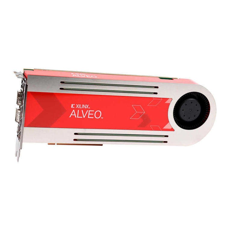
Xilinx T1 User manual

T1 Telco Accelerator Card
Installaon Guide
UG1518 (v1.0) December 17, 2021
See all versions
of this document
Xilinx is creating an environment where employees, customers, and
partners feel welcome and included. To that end, we’re removing non-
inclusive language from our products and related collateral. We’ve
launched an internal initiative to remove language that could exclude
people or reinforce historical biases, including terms embedded in our
software and IPs. You may still find examples of non-inclusive
language in our older products as we work to make these changes and
align with evolving industry standards. Follow this link for more
information.

Table of Contents
Chapter 1: Introduction.............................................................................................. 4
Minimum System Requirements and Setup............................................................................ 5
Configuring the PCIe Slot Bifurcation.......................................................................................6
Chapter 2: Card Information and Installation............................................. 11
Safety Instructions.................................................................................................................... 11
Electrostatic Discharge............................................................................................................. 11
Before You Begin.......................................................................................................................11
Installing the Card.....................................................................................................................12
Chapter 3: Installing Additional Software......................................................13
Chapter 4: T1 Factory Installed Image..............................................................14
Flashing the Images in QSPI Using flash_app....................................................................... 14
Chapter 5: T1 Skeleton Design...............................................................................16
T1 Skeleton Design on the ZU19 Zynq UltraScale+ MPSoC.................................................. 16
T1 Skeleton Design on the ZU21 Zynq UltraScale+ RFSoC................................................... 17
T1 Skeleton Design Package.................................................................................................... 18
Chapter 6: Running the Tests.................................................................................20
100G Internal Connection between Zynq UltraScale+ MPSoC and
Zynq UltraScale+ RFSoC....................................................................................................... 21
2 x 25G External SFP Test......................................................................................................... 23
ZU19 Zynq UltraScale+ MPSoC PCIe Loopback Test..............................................................25
ZU21 Zynq UltraScale+ RFSoC PCIe Loopback Test...............................................................27
DDR Read/Write Tests...............................................................................................................29
Test Application Guide and Address Map.............................................................................. 32
Chapter 7: Next Steps.................................................................................................33
Chapter 8: Dependencies/Known Issues.........................................................34
UG1518 (v1.0) December 17, 2021 www.xilinx.com
T1 Telco Accelerator Card Installation Guide 2
Send Feedback

Appendix A: Programming the Devices Using JTAG.................................. 35
Flashing the Images to ZU19 Zynq UltraScale+ MPSoC QSPI Using SDK........................... 38
Flashing the Images to ZU21 Zynq UltraScale+ RFSoC QSPI Using SDK............................ 40
Programming the Bitstreams Directly ...................................................................................41
Appendix B: Regulatory Compliance Statements...................................... 43
FCC Class A Products.................................................................................................................43
Safety.......................................................................................................................................... 43
EMC Compliance........................................................................................................................44
FCC Class A User Information..................................................................................................44
VCCI Class A Statement............................................................................................................ 45
Appendix C: Additional Resources and Legal Notices............................. 46
Xilinx Resources.........................................................................................................................46
Documentation Navigator and Design Hubs.........................................................................46
Revision History.........................................................................................................................46
Please Read: Important Legal Notices................................................................................... 47
UG1518 (v1.0) December 17, 2021 www.xilinx.com
T1 Telco Accelerator Card Installation Guide 3
Send Feedback

Chapter 1
Introduction
This document provides hardware and soware installaon procedures for the T1 Telco
accelerator card along with a guide to the T1 skeleton design. The skeleton design is created
specically for the 16 nm Zynq® UltraScale+™ MPSoC and Zynq UltraScale+ RFSoC devices on
the T1 card, and provides connecons and soware to validate the main interfaces of the board.
Figure 1: T1 Telco Accelerator Card
The Xilinx® T1 Telco accelerator card is a PCI Express® (PCIe) Gen3 x16 compliant card featuring
the 16 nm Zynq® UltraScale+™ MPSoC and Zynq UltraScale+ RFSoC devices. The T1 form factor
is full height, half length (FHHL) and single slot, with a PCIe Gen 3 x16 interface that is x8x8
bifurcated providing x8 links from the host to each MPSoC and RFSoC device. Target applicaons
for the T1 card include:
• O-RAN fronthaul terminaon
• 4G LTE and 5G NR high-PHY lookaside acceleraon (supporng 3GPP split opon 7-2x)
• 5G layer 1 (L1) high-PHY lookaside acceleraon
Chapter 1: Introduction
UG1518 (v1.0) December 17, 2021 www.xilinx.com
T1 Telco Accelerator Card Installation Guide 4
Send Feedback

•Oponal use of fronthaul ports for a midhaul (F1) interface between distributed and
centralized units (DU and CU)
• 4G LTE and 5G NR inline acceleraon of L1 funcons (supporng 3GPP split opon 7-2x) for
up to 4TRX
The T1 card turns a standard server into a virtual baseband unit with the performance, low
latency, and power eciency needed for O-RAN 5G deployments. The turnkey soluon enables
operators, system integrators, and OEMs to get to market quickly and to simplify the deployment
of services at the edge.
Minimum System Requirements and Setup
The minimum system requirements for running a T1 Telco accelerator card are shown below:
Table 1: Minimum System Requirements
Component Requirement
Motherboard PCI Express 3.0 compatible with one dual-width x16 slot.
System power supply 75W through a PCI Express slot connection
Operating system Linux, 64-bit:
CentOS 7 and 8
Ubuntu 16, 18, and 20
System memory and CPU cores For deployment installations, a minimum of 16 GB plus
application memory requirements is required. For
development installations, a minimum of 64 GB of device
memory is required, but 80 GB is recommended.
A minimum of 16 logical cores is required.
Internet connection Required for downloading drivers and utilities.
Hard disk space Satisfy the minimum system requirements for your
operating system.
Auxiliary power supply No auxiliary power supply is required because the T1 card
cannot boot standalone.
Vitis™ application acceleration development flow The Vitis™ application acceleration development flow is not
currently supported.
The T1 Telco accelerator card is intended for deployment on most servers. Currently, thermal
tesng has been conducted on a Dell R640, and funconal tesng on a number of addional
servers including Dell R730 and R740.
Chapter 1: Introduction
UG1518 (v1.0) December 17, 2021 www.xilinx.com
T1 Telco Accelerator Card Installation Guide 5
Send Feedback

Configuring the PCIe Slot Bifurcation
Perform the following steps to enable bifurcaon in the slot where the T1 card has been
inserted. This is required for the T1 card to work properly.
Note: These steps are for a single T1 card deployment.
1. Power on the server. The output on the monitor is shown below.
2. Wait unl the monitor lists the shortcut keys, so you can navigate into the setup. The screen
with the shortcut keys looks like the following gure.
Chapter 1: Introduction
UG1518 (v1.0) December 17, 2021 www.xilinx.com
T1 Telco Accelerator Card Installation Guide 6
Send Feedback

3. Press F2 to open the system setup sengs.
4. In the System Setup screen, select the System BIOS opon as shown below.
5. Select Integrated Devices.
6. In the menu that is displayed, scroll down unl you get to Slot Bifurcaon. It is on the second
half of the page.
Chapter 1: Introduction
UG1518 (v1.0) December 17, 2021 www.xilinx.com
T1 Telco Accelerator Card Installation Guide 7
Send Feedback

7. Click the required slot to change bifurcaon.
8. Click Default Bifurcaon and select x8x8 or x8 Bifurcaon. This enables the T1 card in the
slot with the correct communicaon over the PCI. Click the Back buon in the lower right
hand side of the screen.
Chapter 1: Introduction
UG1518 (v1.0) December 17, 2021 www.xilinx.com
T1 Telco Accelerator Card Installation Guide 8
Send Feedback

9. Return to the System BIOS screen and click the Back buon again.
10. In the System BIOS Sengs main menu screen, click Finish.
11. A popup window will show a warning, as shown below. Click Yes to save the changes you
made.
12. Click the Finish buon again.
13. When the system has rebooted, check to see if the T1 card has been detected using the
lspci | grep Xilinx command. If the card has been detected, the response should look
like the following gure.
Chapter 1: Introduction
UG1518 (v1.0) December 17, 2021 www.xilinx.com
T1 Telco Accelerator Card Installation Guide 9
Send Feedback

Chapter 2
Card Information and Installation
Safety Instructions
To ensure your personal safety and the safety of your equipment:
• Keep your work area and the computer/server clean and clear of debris.
• Before opening the computer/system cover, unplug the power cord.
Electrostatic Discharge
Electrostac discharge (ESD) can damage electronic components when they are improperly
handled, and can result in total or intermient failures. Always follow ESD prevenon procedures
when removing and replacing components. To prevent ESD damage:
• Use an ESD wrist or ankle strap and ensure that it makes skin contact. Connect the equipment
end of the strap to an unpainted metal surface on the chassis.
• Avoid touching the card with your clothing. The wrist strap protects components from ESD on
the body only.
• Handle the card by its bracket or edges only. Avoid touching the printed circuit board or the
connectors.
• Put the card down only on an anstac surface such as the bag supplied in your kit.
• If you are returning the card to Xilinx product support, place it back in its anstac bag
immediately.
Before You Begin
IMPORTANT! The T1 Telco accelerator card is a delicate and sensive electronic device and should be
installed by a qualied technician only. This equipment is intended for installaon in a restricted access
locaon.
Chapter 2: Card Information and Installation
UG1518 (v1.0) December 17, 2021 www.xilinx.com
T1 Telco Accelerator Card Installation Guide 11
Send Feedback

• Verify that the minimum card space is available to install your card.
• Check for card compability with your system. Check system requirements such as power, bus
type, and physical dimensions to support the card.
Installing the Card
The following procedure is a guide to T1 Telco accelerator card PCI x16 installaon. Consult your
computer documentaon for addional informaon.
Note: This procedure is for use with UL Listed Servers or ITE.
1. Ensure that the host power supply is disconnected.
2. If you are working with an enclosed computer, open your computer by removing the casing.
3. If necessary, remove the adjacent PCIe slot cover corresponding to the PCIe slot in which you
are installing the card.
4. Plug the T1 card into the bifurcated PCIe x16 slot on the motherboard.
Note: There is no auxiliary power connector on the T1 card.
Note: There is also a USB JTAG connector that can be connected from the server to the T1 card. It can
be used to program the ash. This is for development purposes and is not intended for use in a
producon seng.
Chapter 2: Card Information and Installation
UG1518 (v1.0) December 17, 2021 www.xilinx.com
T1 Telco Accelerator Card Installation Guide 12
Send Feedback

Chapter 3
Installing Additional Software
To run the T1 card skeleton design or other demos provided by Xilinx partners, install the
following addional soware on the server:
• DPDK package. The supported versions are 18.11, 19.11, and 20.11.
• DPDK-based pktgen applicaon. The following versions are supported:
○DPDK 18.11 – pktgen-3.6.1
○DPDK 19.11 – pktgen-19.12.0
○DPDK 20.11 – pktgen-21.05.0
Note: For DPDK version 20.11, the DPDG kernel modules are no longer included in the DPDK
package. The dpdk-kmods package is therefore included in the T1 card skeleton design package.
•Applicaon scripts
This soware is included in the T1 skeleton design package along with a script to ensure that the
soware is installed correctly. The package and the scripts are described in the T1 Skeleton
Design Package secon of this document.
The demos provided by Xilinx partners also contain the addional soware. For each design or
demo, there is a local directory for the addional soware as well as instrucons on building it
for the parcular design. There is no central locaon on the server for these demos.
The soware has been tested on the following Linux distribuons: Ubuntu 18, Ubuntu 20,
CentOS 7, and CentOS 8.
To run the Xilinx demos, the requirements are as follows:
• Root access is required.
• HugePages is enabled.
Chapter 3: Installing Additional Software
UG1518 (v1.0) December 17, 2021 www.xilinx.com
T1 Telco Accelerator Card Installation Guide 13
Send Feedback

Chapter 4
T1 Factory Installed Image
The T1 Telco accelerator card is preprogrammed with an image in the QSPIs on the card that
consists of two separate designs that support the two Xilinx® devices: the Zynq® UltraScale+™
MPSoC (ZU19) and the Zynq UltraScale+ RFSoC (ZU21). Each of the designs provides simple
connecvity from the host sever to the card and the two devices.
The latest T1 factory installed image includes the latest T1 skeleton design.
Flashing the Images in QSPI Using flash_app
As part of the manufacturing design, an applicaon called ash_app runs on processors on the
two devices. This applicaon allows you to program 5G acceleraon soluons on the T1 card. An
alternave method using the JTAG/USB cable and Xilinx tools is described in Appendix A:
Programming the Devices Using JTAG.
The following secons describe how to set up the ash_app code to program the QSPI that is
connected to the ZU19/Zynq UltraScale+ MPSoC or the ZU21/Zynq UltraScale+ RFSoC device.
Flashing the Images to ZU19 Zynq UltraScale+ MPSoC
QSPI Using flash_app
1. Ensure that the PCIe PFs for ZU19 Zynq UltraScale+ MPSoC are visible in the lspci
command.
2. Execute ./mpsoc_flash_qspi.sh <MPSOC BOOT.BIN absolute file path>
[<QSPI flash offset> [<PCIe BDF>]] inside the flash_app directory.
3. Wait unl the message “Programmed boot image” appears.
Flashing the Images to ZU21 Zynq UltraScale+ RFSoC
QSPI Using flash_app
1. Ensure that the PCIe PFs for ZU21 Zynq UltraScale+ RFSoC are visible in the lspci
command.
Chapter 4: T1 Factory Installed Image
UG1518 (v1.0) December 17, 2021 www.xilinx.com
T1 Telco Accelerator Card Installation Guide 14
Send Feedback

2. Execute ./rfsoc_flash_qspi.sh <RFSOC BOOT.BIN absolute file path>
[<QSPI flash offset> [<PCIe BDF>]] inside the flash_app directory.
3. Wait unl the message “Programmed boot image” appears.
Flashing the SC Image Using the sc_flash Script
1. Verify the SC state. Execute ./sc_flash.sh get_sc_state. The card should be in
normal mode before wring the SC image, as shown below:
SC is in NORMAL mode
2. Verify the SC rmware version. Execute ./sc_flash.sh get_sc_fw_version. A
possible successful output is shown below:
SC fw version: 01.02.00
3. Bring the card in FW_AVAILABLE mode. For the rst me, execute ./sc_flash.sh
<image_name> <bsl_password_file>. The expected output is as follows:
"Please reboot the Host and re-run the command"
4. Reboot the host.
5. Program the SC image. For the second me, execute ./sc_flash.sh <image_name>
<bsl_password_file>.
Running host Application
Fw upgrade started
Fw image Data > @0[16]
Fw image Data > @200[16]
Fw image Data > @1AE20[16]
Fw image Data > @3F000[16]
[flash_mem_sections] : 4
BslPasswordSize:56
Programming SC firmware image... (100%)
Programmed SC firmware image done successfully
6. During the upgrade, the SC state should be FW_UPDATE, as shown below.
SC is in FW_UPDATE mode
Execute ./sc_flash.sh get_sc_state.
Chapter 4: T1 Factory Installed Image
UG1518 (v1.0) December 17, 2021 www.xilinx.com
T1 Telco Accelerator Card Installation Guide 15
Send Feedback

Chapter 5
T1 Skeleton Design
The T1 card skeleton design consists of two separate designs that support the two Xilinx®
devices (ZU19/Zynq® UltraScale+™ MPSoC and ZU21/Zynq® UltraScale+™ RFSoC) on the card.
Each of the designs provides connecvity with the ports on the board from the two devices, and
the ZU21 to the ZU19. There is also a 25G x 4 100G Ethernet connecon between the ZU19
and ZU21 devices. These two designs allow tesng of the connecvity from the host to the card
and between the two devices to demonstrate that the board is fully funconal.
Note: The T1 skeleton design is limited to working only in even-numbered PCIe slots. If you use an odd-
numbered slot, designs can be loaded into the devices, but the tests described in Chapter 6: Running the
Tests do not run.
T1 Skeleton Design on the ZU19
Zynq UltraScale+ MPSoC
The design on the ZU19 Zynq UltraScale+ MPSoC has Linux running on the PS Cortex®-A53
processors and has connecons from the PCIe Gen3 x8 from the host to the dierent parts of
the ZU19. These connecons are accomplished through AXI interconnect. These connecons are
as follows:
• Processing system and its DDR
• PL DDR through a MIG DDR controller
• 100G MAC
• Two 25G MAC connecons
The block diagram below shows the connecons.
Chapter 5: T1 Skeleton Design
UG1518 (v1.0) December 17, 2021 www.xilinx.com
T1 Telco Accelerator Card Installation Guide 16
Send Feedback

Figure 2: ZU19 Skeleton Design Connections
T1 Skeleton Design on the ZU21
Zynq UltraScale+ RFSoC
The design on the ZU21DR Zynq UltraScale+ RFSoC has Linux running on the PS Cortex-A53
processors and has connecons from the PCIe Gen3 x8 from the host to the dierent parts of
the ZU21. These connecons are accomplished through AXI interconnect. These connecons are
as follows:
• Processing system and its DDR
• PL DDR through a MIG DDR controller
• 100G MAC
The block diagram below shows the connecons.
Chapter 5: T1 Skeleton Design
UG1518 (v1.0) December 17, 2021 www.xilinx.com
T1 Telco Accelerator Card Installation Guide 17
Send Feedback

Figure 3: ZU21 Skeleton Design Connections
T1 Skeleton Design Package
The T1 card skeleton design package comes as a Git repository. The code is stored in dierent
branches, with one separate branch for each supported DPDK version (18.11, 19.11, and 20.11).
Figure 4: Git Branch Structure
Chapter 5: T1 Skeleton Design
UG1518 (v1.0) December 17, 2021 www.xilinx.com
T1 Telco Accelerator Card Installation Guide 18
Send Feedback

The les are described below.
•build.sh: This script downloads all packages from the Internet and applies Xilinx patches.
•compile.sh: This script is used to compile the addional host soware required to run the
design.
•test.sh: This script is used to run all the tests described in Chapter 6: Running the Tests.
When you have downloaded the package, select the branch for the correct DPDK version, then
run build.sh followed by compile.sh at the root directory level.
Chapter 5: T1 Skeleton Design
UG1518 (v1.0) December 17, 2021 www.xilinx.com
T1 Telco Accelerator Card Installation Guide 19
Send Feedback

Chapter 6
Running the Tests
The skeleton design has the following setup to test the T1 card.
Figure 5: Test Setup
Dell PowerEdge R740 Server
Pktgen Application
Port 1
Pktgen Application
Port 2
QDMA Poll Mode Driver
PCIe x16
Xilinx® T1 Telco Card
MPSoC
PCIe x8
25G_0
25G_1
25G_2
25G_3
25G_4
25G_5
PS
RFSoC
PCIe x8
25G_0
25G_1
25G_2
25G_3
PS
DDR
2G
DDR
4G
DDR
4G
DDR
2G
SFP
X25234-033121
The following secon describes each test, including setup, running, and expected results. The
primary objecve of tesng is to verify the following main interfaces, and then to verify data
transfer by comparing the output with expectaons.
• 100G internal MAC connecon between Zynq UltraScale+ MPSoC and
Zynq UltraScale+ RFSoC
Chapter 6: Running the Tests
UG1518 (v1.0) December 17, 2021 www.xilinx.com
T1 Telco Accelerator Card Installation Guide 20
Send Feedback
Other manuals for T1
1
Table of contents
Other Xilinx PCI Card manuals
Popular PCI Card manuals by other brands

Assmann
Assmann Digitus DS-30224 manual

Broadcom
Broadcom BCM94301MPL user guide

Transition Networks
Transition Networks N-FXE-02 Series user guide

König Electronic
König Electronic CMP-SATAPCI30 manual

StarTech.com
StarTech.com USB32HDCAPRO quick start guide

Texas Instruments
Texas Instruments SW14J59EVM JESD204C user guide