Introduction
Chapter 3
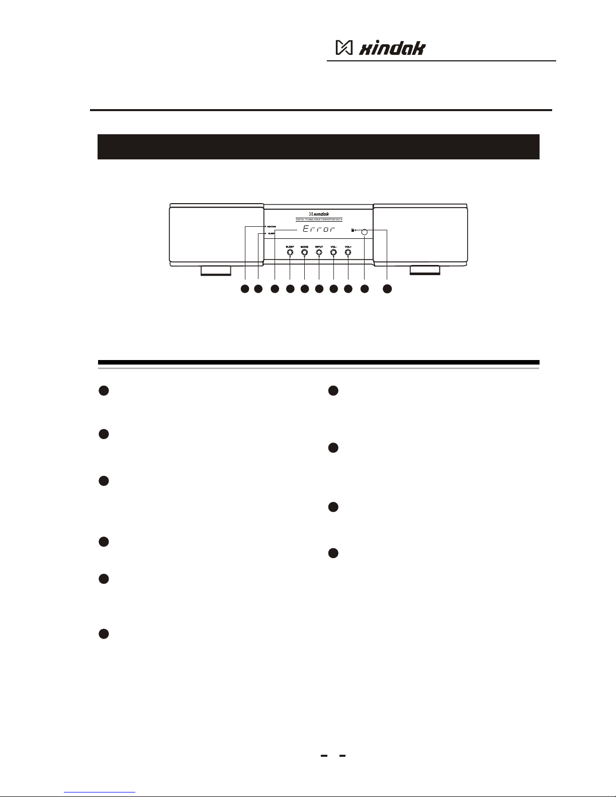
3.3 Front panel
5
5
7
8
9
1
2
3
4
Indicator for warm-up:
It needs 30 seconds for system warm-up after
power on. During this period, the window will display
the rest warm-up time needed.
Sleep indicator:
Press the sleep button on panel or power button on
remote control, and then the D/A converter will enter
"sleep" mode this indicator will be light.
Receiver error indicator:
When there is serial data which is no PCM format
inputted from optical fiber or coaxial input, or plug
and unplug the digital cable in wrong way, the
product will stop work and enter production state.
The display screen will display "error".
Sleep button:
Press this button to make the D/A converter enter
"sleep" mode.
Mode button:
Press this button, can set the work mode as
192kHz/24bit or 96kHz/24bit. The display screen will
display corresponding work mode.When the input
is USB, this button does not work.
Input Selection Button:
Press this button can select between "COA”
coaxial input, "Opt” optical fiber input and PC
USB digital input. The display screen will
display the corresponding input way.
10
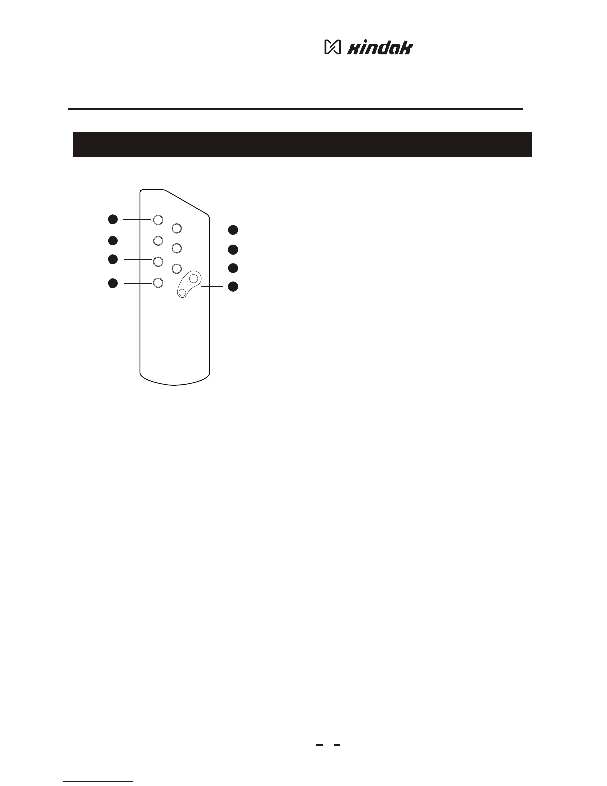
DAC-8
IR SensoerIR Sensoer
3 4 5 7 8
6
21 9
Vol- button:
Press this button can reduce analogy output
volume. The display screen will display current
volume level. Min is 0. When the input is USB,
this button does not work.
Vol+ button:
Press this button can increase the analog
volume, and the display screen will display
current volume level, max is 60.When the input
is USB, this button does not work.
Sensor window for remote control
The remote control receiving window will
receive the controlling signal produced by the
remote controller.
Digital Signal locked indicator:
This indicator will be light when the steady digital
signal are received. When the input is USB, this button
does not work.
10
6