XOCECO LC-40T7 User manual

LCD TELEVISION
LC-40T7

CONTENTS
Safety precautions………………………………………………………………………..…
Alignment instructions …………………………….…….…………………………….…
Working principle analysis of the unit……………………………….………….………….
Block diagram…………………………………..………………………………….…………
IC block diagram………………………………………………………………………..……
Wiring diagram ……………………………………………………………………………..…
Troubleshooting…………………………………………………………………………..……
Schematic diagram …………………………………………………………………….…..
APPENDIX: Exploded View
1
3
6
8
9
17
18
25

1
Safety precautions
1. Instructions
Be sure to switch off the power supply before replacing or welding any components or
inserting/plugging in connection wire Anti static measures to be taken (throughout the entire
production process!):
a) Do not touch here and there by hand at will;
b) Be sure to use anti static electric iron;
c) It’s a must for the welder to wear anti static gloves.
Please refer to the detailed list before replacing components that have special safety requirements.
Do not change the specs and type at will.
2. Points for attention in servicing of LCD
2.1 Screens are different from one model to another and therefore not interchangeable. Be sure to
use the screen of the original model for replacement.
2.2 The operation voltage of LCD screen is 700-825V. Be sure to take proper measures in
protecting yourself and the machine when testing the system in the course of normal operation or
right after the power is switched off. Please do not touch the circuit or the metal part of the module
that is in operation mode. Relevant operation is possible only one minute after the power is
switched off.
2.3 Do not use any adapter that is not identical with the TV set. Otherwise it will cause fire or
damage to the set.
2.4 Never operate the set or do any installation work in bad environment such as wet bathroom,
laundry, kitchen, or nearby fire source, heating equipment and devices or exposure to sunlight etc.
Otherwise bad effect will result.
2.5 If any foreign substance such as water, liquid, metal slices or other matters happens to fall into
the module, be sure to cut the power off immediately and do not move anything on the module lest it
should cause fire or electric shock due to contact with the high voltage or short circuit.
2.6 Should there be smoke, abnormal smell or sound from the module, please shut the power off at
once. Likewise, if the screen is not working after the power is on or in the course of operation, the
power must be cut off immediately and no more operation is allowed under the same condition.
2.7 Do not pull out or plug in the connection wire when the module is in operation or just after the
power is off because in this case relatively high voltage still remains in the capacitor of the driving
circuit. Please wait at least one minute before the pulling out or plugging in the connection wire.
2.8 When operating or installing LCD please don’t subject the LCD components to bending, twisting
or extrusion, collision lest mishap should result.
2.9 As most of the circuitry in LCD TV set is composed of CMOS integrated circuits, it’s necessary
to pay attention to anti statics. Before servicing LCD TV make sure to take anti static measure and
ensure full grounding for all the parts that have to be grounded.
2.10 There are lots of connection wires between parts behind the LCD screen. When servicing or
moving the set please take care not to touch or scratch them. Once they are damaged the screen
Attention: This service manual is only for service personnel to take reference with. Before
servicing please read the following points carefully.

2
would be unable to work and no way to get it repaired.
2.11 Special care must be taken in transporting or handling it. Exquisite shock vibration may lead to
breakage of screen glass or damage to driving circuit. Therefore it must be packed in a strong case
before the transportation or handling.
2.12 For the storage make sure to put it in a place where the environment can be controlled so as to
prevent the temperature and humidity from exceeding the limits as specified in the manual. For
prolonged storage, it is necessary to house it in an anti-moisture bag and put them altogether in one
place. The ambient conditions are tabulated as follows:
Temperature Scope for operation 0 ~ +50 oC
Scope for storage -20 ~ +60 oC
Humidity Scope for operation 20% ~ 85%
Scope for storage 10% ~ 90%
2.13 Display of a fixed picture for a long time may result in appearance of picture residue on the
screen, as commonly called “ghost shadow”. The extent of the residual picture varies with the
maker of LCD screen. This phenomenon doesn’t represent failure. This “ghost shadow” may remain
in the picture for a period of time (several minutes). But when operating it please avoid displaying
still picture in high brightness for a long time.
3. Points for attention during installation
3.1 The front panel of LCD screen is of glass. When installing it please make sure to put it in place.
3.2 For service or installation it’s necessary to use specified screw lest it should damage the screen.
3.3 Be sure to take anti dust measures. Any foreign substance that happens to fall down between
the screen and the glass will affect the receiving and viewing effect
3.4 When dismantling or mounting the protective partition plate that is used for anti vibration and
insulation please take care to keep it in intactness so as to avoid hidden trouble.
3.5 Be sure to protect the cabinet from damage or scratch during service, dismantling or mounting.

3
Alignment instructions
1. Test equipment
Digital multimeter, signal generator (54200)
PC set (FLASH writing programs and W24CXX.EXE have to be installed first,)
VG849 (HDMI signal generator)
CA210 (White balancer), DVD player(with HDMI output), monitor
2. The alignment flow chart (see below Fig.1)
Fig.1 Flow process of alignment
Check accessories and then packing
Write N105, N403, N607, N70, N606
To produce main board, TV board and other board
Check the MAIN board
Check the buttons board and IR receive board
Combined test for general assembly
Input AV1/S/AV2 signal source, check if the
various terminal functions (system identify an
d
analog control etc.) and the picture and sound o
f
AV-out is normal. (S-terminal shares the same
audio channel with AV1, and it can be auto
identified)
Check the TV board
Input YPbPr/YCbCr 1/2 signal source; check i
f
the picture and sound analog control is normal i
n
the COMPONENT state. The AV-out output soun
d
is originally signal
Input HDMI and DVI signal source, check if
the HDCP KEY is normal. The AV-out outpu
t
sound is originally signal
Input VGA signal source, check is the display is
n
ormal in PC state and various function (analog
control) H-V center etc. The AV-out output soun
d
is originally signal
Aging
Input the center signal source, check if various
functions of TV (search channel, system identify
and analog control etc.), earphone output, speake
r
output and the picture and sound of AV-out is
normal. (check stereo/SAP, CCD and VCHIP fo
r
American unit)
ADC correction and white balance adjustment

4
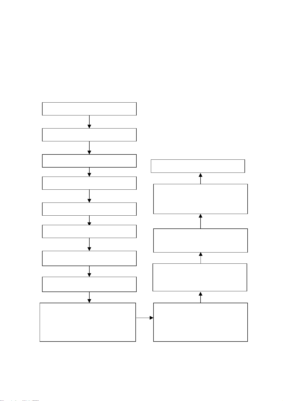
3. Alignment instructions
3.1 flash write programs
Flash write N606, N607, N105, N403, N701
Flash write W24CXX.EXE into N102 with self-made flash write tool on the line.
Note: N606 may upgrade from the socket X1
N701 may upgrade from the serial wire
N102, N403 may upgrade from HDMI and VGA interface respectively
N105 can not upgrade on the line, so ensure HDCP KEY is right
3.2 the main board adjustment
a. Connect the X602 of main board to the infrared receive board, the supply power plug to X1, then
the indicator of the infrared receive board is red light.
b. Press the POWER button; the indicator change to blue light, the LED1 of main board is flicker of
slow.
c. Write EDID program to N102
d. Check if various channels are normal.
3.3 The TV board adjustment
a. Connect the high frequency board to main board, and connect the X501 and X502 to the supply
power.
b. Press the POWER button, the indicator change to blue light.
c. Check if the picture and sound of TV/AV1/AV2/S/YPBPR1/YPBPR2 and sound of HDMI/VGA
channels are normal. Check the STEREO and SAP. Check AV-OUT function: the picture and
sound of AV-OUT should be the picture and sound of the current channel at TV/AV1/S/AV2, at
other signal source, the sound of AV-OUT should be the sound of the current channel, but the
picture don’t need to check.
3.4 the unit adjustment
After install the unit, check it is normal working.
3.5 Aging
a. Select the TV channel, the screen is noise wave of no signal TV
b. Aging an hour.
3.6 ADC correction and white balance adjustment (use white balancer CA210 and signal generator
VG849)
Enter the factory menu method: press “1”→“9” →“7” →“9” button in the window menu state
a. Enter VGA channel,input 16 level gray signal of 1024*768@60Hz(TIMING:889, PATTERN:921).
b. Enter PICTURE menu, set “Color Temp” to “Middle”
c. Enter the factory menu, press AUTO ADC CALIBRATION and operate according the prompt.
d. Input 8 level gray signal of 1024*768@60Hz and test the fourth level with CA210, adjust the
brightness until the brightness value of CA210 is 180±10nit. Enter “color temperature” item, fix
“red color temperature”, adjust “blue color temperature” and “green color temperature” so that
x=0.284±0.02, y=0.299±0.02.
e. Enter YPBPR channel, input 720P SMPTE COLOR BAR signal(TIMING:976, PATTERN:984)
f. Enter factory menu, press AUTO ADC CALIBRATION and operate according the prompt.
g. Input 720P 8 level gray signal and test the fourth level with CA210, adjust the brightness until
the brightness value of CA210 is 180±10nit. Enter “color temperature” item, fix “red color
temperature”, adjust “blue color temperature” and “green color temperature” so that
x=0.284±0.02, y=0.299±0.02.

5
4 Performance check
4.1 TV terminal
Input the center signal source to RF terminal, enter searching menu →auto search, check if the
leak channel, half-auto search channel, fine tune, earphone and speaker are normal. Check
stereo/SAP/CCD/ Parent Control for America unit. Check the AV OUT.
4.2 AV1/S/AV2 input terminals
Input AV1/S/AV2 signal source, check the picture, sound and the output of AV-OUT. Check if it can
auto-jump to S-terminal when insert S-terminal at AV1 state.
4.3 VGA terminal
Input the VGA signal (K7253 signal generator), separate input VGA format signal of table 1, check
the picture and sound
Table1 PC display format signal
No. Resolution H-frequency(kHz) V-frequency(Hz) pixel clock pulse
frequency(MHz) remark
1 720 x 400 31.47 70.08 25.17 DOS
2 640 x 480 31.50 60.00 25.18 DOS
3 640 x 480 37.90 72.00 31.50 Mac.(SOG)
4 640 x 480 37.50 75.00 31.50 VESA
5 640 x 480 43.30 85.00 36.00 VESA
6 800 x 600 35.16 56.25 36.00 VESA
7 800 x 600 37.90 60.00 40.00 VESA
8 800 x 600 46.90 75.00 49.50 VESA
9 800 x 600 48.08 72.19 50.00 VESA
10 832 x 624 49.00 74.00 57.27 Mac.(H+V)
11 1024 x 768 48.40 60.00 65.00 VESA
12 1024 x 768 56.50 70.00 75.00 VESA
13 1024 x 768 60.00 75.00 78.75 VESA
14 1280 x 1024 64.00 60 108.00 SXGA
15 1280 x 1024 80.00 75 135.00 SXGA
4.4 YPbPr terminal
Input the YPbPr signal source (K7253 signal generator), separate input format signal of table 2, and
check the picture and sound. If the image is slight disturb, press auto correction button of the
remote controller and check if it is normal.
Table 2 Component format signal
No. H-frequency(kHz) V-frequency(Hz) signal
1 15.735 60 SDTV 480i
2 15.625 50 SDTV 576i
3 31.47 60 SDTV 483p
4 45.00 60 HDTV 720p
5 33.75 60 HDTV 1080i
6 28.13 50 HDTV 1080i

6
4.5 HDMI terminal
Input the DHMI signal source (VG849 signal generator), separate input format signal of table 3,
check the picture and sound.
Table 3 HDMI format signal
No. H-frequency(kHz) V-frequency(Hz) signal
1 15.735 60 SDTV 480i
2 15.625 50 SDTV 576i
3 31.47 60 SDTV 483p
4 45.00 60 HDTV 720p
5 33.75 60 HDTV 1080i
6 28.13 50 HDTV 1080i
HDMI format signal of audio
channel 2
sampling rate support 32Kbit/s 44.1Kbit/s 48Kbit/s
bit wide support 16bit,20bit,24bit
4.6 Ex-factory preset
Enter the factory menu in the status of TV, then perform the ex-factory preset.
4.7 Packing
Check the accessories and then packing.
Working principle analysis of the unit
The unit has two MCU, the main MCU is PW218 (N601): it is used to control all the chips’ working
status on the main board (including image processing, channel switch, sound processing, image
display etc.), sub CPU, OSD, searching channels, image effect adjustment, buttons control, infrared
remote control etc.; the sub CPU is ATMEGA8L (N606): it is used to control power supply, including
standby and turning on the unit by using remote control etc.. The two MCU correlates with each
other through pin 14 INT (interruption) of ATMEGA8L, pin 28 and 29 SDA, SCL.
This unit adopts the integrative tuner (contains HF and IF amplifier circuits), antenna reception
signal will be sent to tuner, the tuner is controlled by SDA, SCL of the MCU PW218(N601),selects
appropriate channel to system switch, via HF and IF amplifier decoder, outputs video and sound
signal. Video signal of tuner will be sent to decoder PW2300 (N201), while Audio signal of the tuner
will then be sent to AV switch box M52797 (N400), the audio signal of AV1, AV2 and HD2 of the
main board will also be sent to M52797 (N400) at the same time. The selected audio signal after
switching will be sent to MSP3425, and then switching selection will be done towards the above
audio signal together with the audio signal of VGA, HDMI and HD1. The two chips are controlled by
PW218 (N601), after the above process the finally selected way will be sent to X300 earphone
socket after under the control of volume, treble and bass, the earphone socket has the switching
function, when earphone is plugged, sound will be sent to earphone amplifier LM4808, then sent
back to earphone socket after power amplification. If earphone is unplugged, sound will be sent to
sound amplifier TPA3008 to do amplification and then sent to speaker.

7
Image parts:
Video signal of TUNER will be sent to AV switch M52797 (N400), Video signal of AV1 and AV2 will
also be sent to M52797 (N400) at the same time, two groups of video output will be obtained after
switching, one group of video output together with its audio output will be sent to AV_OUT terminal
to treat as AV OUT. The other group of video output together with other video signals such as
S-VIDEO, YPbPr1, YPbPr2 and VGA will be sent to PW2300 to do video decoding or AD
transformation, then output 24bit digital RGB signal and some corresponding synchronous signals.
Items such as 3D comb filter, channel switching, 5 lines Y/C separation and color decoding etc. are
primarily done by PW2300. 24bit digital RGB signal and some corresponding synchronous signals
outputted by PW2300 will then be sent to PW218 (N601). HDMI signal will also be sent to AD9398
(N101) to do decoding and output 24bit digital RGB signal as well as some corresponding
synchronous signal, which will be sent to PW218 (N601). PW218 is a new generation chip of
Pixelworks, which has ability to deal with images, 24bit digital RGB signal and some corresponding
synchronous signals outputted by AD9398 and PW2300 will be sent to this chip to deal with images.
The chip has functions such as converting from interleaved into line-by-line and image
enhancement etc.. PW218 has SCALER function which can do format conversion towards different
input formats so as to meet the format needs of the screen and finally output 24bit RGB signal. The
interface standard of PDP screen is generally LVDS (low voltage differential signal), so PW218 send
LVDS to drive the screen. PW218 is also the main CPU, its programs are stored in periphery device
flash N701, and software upgrade through RS-232 interface is virtually upgrading the stored
programs through PW218 towards N701.
Chief functions:
High definition 1080P LCD
16:9 wide screen; Support several kinds of HDTV wide voltage range, low standby power
consumption (less than 1W); One group of D-SUB, S-VSH (Y/C), RS232, AVOUT, HEADPHONE,
HDMI, two groups of YPbPr/YCbCr, AV.

N400
M52797SP
Audio and video
switch
PW218C
Flash
DDR 256M
SDRAM
V port
G port
PW2300
S Video
EEPROM
24LC32
I2C2
KEY
E2PROM
PW2300
HDMI AD9880
or AD9398
PC
YPbPr2 Audio
Tuner
YPbPr1 Audio
RF Video
RF Audio
I2C1
AV1
AV2
memory
LM4808
TPA3008D2
MSP3425
STERO/SAP decoder
Earphone
socket
with switch
PC Audio HDMI Audio
YPbPr2
YPbPr1
RS232
AV Audio Out
CS4334
LCD Panel
MEGAL8 IR
KEY
AV Out
MAX3232C
Block diagram
8

9
IC block diagram
1. AD9880 and AD9398
AD9880 have HDMI digital and analog terminal of working frequency 165Hz, it support 1080P
(non-interlaced scanning) and UXGA (1600 x 1200/60Hz) video format, also it support eight audio
channel of 192KHz. AD9398 without analog terminal.
Internal Block Diagram

10
PIN configuration
AD9880 (AD9398) PINS FUNCTIONS
Pin Name Function Pin Name Function
2-9 GGE(0-7) Converter output 44 RXC+ DVI input
12-19 GBE(0-7) Converter output 49 DDC_CLK HDCP Slave Serial Port
Data Clock
92-99 GRE(0-7) Converter output 50 DDC_DATA HDCP Slave Serial Port
Data I/O
20, 21 MCLK Control clock output 51 MCL HDCP Master Serial Port
Data Clock
22 I2S_SCK Audio serial clock output 52 MDA HDCP Master Serial Port
Data I/O
23 I2S_WS Bus clock data output 82 SCL-1 Serial Port Data Clock

11
27 I2S_SD Bus audio data output 83 SDA_1 Serial Port Data I/O
34 RX0- DVI input 84 G_FIEL0 Odd/Even Field Output
35 RX0+ DVI input 85 G_VS VSYNC Output Clock
37 RX1- DVI input 86 G_VHS Sync on Green Slicer
Output
38 RX1+ DVI input 87 G_HS HSYNC Output Clock
40 RX2- DVI input 88 G_DE Data Enable
41 RX2+ DVI input 89 G_CLK Data Output Clock
43 RXC- DVI input
2. PW2300
PW2300 is front processing signal of integration highly performance, multi-system, 3D video
decoder and three highly velocity AD converter chip. It supports HDTV, NTSC, PAL and SECAM. Its
analog port support 1080P(150MHz).
Internal Block Diagram
PW2300 PINS FUNCTION
Pin Name Function Pin Name Function
A4 XIN Resonator input P1 R_2 AV2 red input
A5 XOUT Resonator input P2 B_2 AV2 greed input
B2 SDA I2C bus data P3 SOG_2 AV2 greed sync input
B3 SCL I2Cbus clock P4 G_2 AV2 blue input
C5 R1 CVBS_1 TV composite video signal input
D5 R2 Y_1 S-VHS brightness signal input
K2 VGA-R1 VGA(red) R3 CVBS_SOG1 TV composite video signal greed sync
input
K1 VGA-G1 VGA(greed) R4 C_1 S-VHS chrominance signal input
L1 VGA-SOG1 VGA(greed sync signal) AB S_DECT

12
M1 VGA-B1 VGA(blue) B9 GVBI Vertical blanking blank
T1 VGA_H VGA(H-sync signal) E15 GFIELD
T3 VGA_V VGA(V-sync signal) E16 G_VS V-SYNC output
N1 R_1 AV1 red input F14 G_HS H-SYNC output
N1 G_1 AV1 greed input F15 G_AHS H-SYNC of non-processing
N3 SOG_1 AV1 greed sync input F16 G_DE
N4 B_1 AV1 blue input G15 G_DLK Clock output
GBO(2-9) Blue odd pixel data output GBE(0-7) blue even pixel data output
GGO(2-9) greed odd pixel data output GGE(0-7) greed even pixel data output
GRO(2-9) red odd pixel data output GRE(0-7) red even pixel data output
3. PW218
PWE218 is highly quality SOC picture processing chip, it contains Scaling and Deinterlacing
functions.
Internal Block Diagram
4. TPA3008
TPA3008 is double channel 10W stereo D class audio amplifier.
Internal Block Diagram

13
PINS FUNCTION
Pin Name Function Pin Name Function
1 SHUTDOWN Shut down control signal 17 LOUTN Negative audio output for left channel
3 RINP Positive audio input for right channel 20 LOUTP Positive audio output for left channel
4 V2P5 2.5V Reference for analog cells. 27 ROSC I/O current setting resistor for ramp
generator.
5 LINP Positive audio input for left channel 41 ROUTP Positive audio output for right channel
11 FAULT Volume control 44 ROUTN Negative audio output for right channel
5. M52797D
The M52797 is AV switch semiconductor integrated circuit with I2C bus control.
Internal Block Diagram

14
Pin description
Pin Name Description Pin Name Description
3 HD2_L Audio input 5 HD2_R Audio input
6 AV1_L Audio input 8 AV1_R Audio input
9 AV2_L Audio input 11 AV2_R Audio input
27 TV_L Audio input 25 TV_R Audio input
24 Left audio channel output 22 Right audio channel output

15
6.CM2006
It includes ESD protection, level-shifting, buffering and sync impedance matching
Internal Block Diagram
Pin description
Pin Name Description Pin Name Description
1 VCC 3.3V 11 DDC_IN2 DDC _input2
3, 4, 5 VIDEO_1_2_3 Video input 12 DDC_OUT2 DDC output
6 GND GND 13 SYNC_IN1 Sync input1
7 Vcc-DDC 5V DDC 14 SYNC_OUT1 Sync output1
8 BYP Bypass capacitance 15 SYNC_IN2 Sync intput2
9 DDC_OUT1 DDC output 16 SYNC_OUT2 Sync output2
10 DDC_IN1 DDC _output1
7. MSP3425
The MSP 34X5G family of single-chip Multistandard Sound Processors covers the sound
processing of all analog TV standards worldwide, as well as the NICAM digital sound
standards. The full TV sound processing, starting with analog sound IF signal-in, down to
processed analog AF-out, is performed in a single chip. Figure below shows a simplified
functional block diagram of the MSP 34X5G.

16
Pin description
Pin Description Pin Description
2 SIF IN 29 AVOUT_R
12 I2C_CL 30 AV OUT_L
13 I2C_DA 40 SC1_IN_L
25 OUT_R 41 SC1_IN_R
26 OUT_L 42 VEEFTOP
43 MONO_IN

782-LYT25-0100
12
782-LYT25-5500
\
Power module
X3(12)X4 X6 X5 X603
X500 X604 X602 X603
X608
TUNER
X601
X101
X401
X402
X8
X7
XA01
CN2 CN3 CN4 CN5
CN1
RS-232C
HDMI
VGA
VGA AUDIO IN
S-VIDEO
AC220
Speaker
HEADPHONE
KEY BOARD
Remote receiver
X602
X607
X605
X606
X601
X300
X700
X502
X501
LCD panel
X604
CNF1 J1
CN2
CN1
2 YPBPR
YPBPR audio IN
AV I N
AV OUT
Wiring diagram
17

18
Trouble shooting
1. Fault clearance
Before servicing please check to find the possible causes of the troubles according to the table
below.
1.1 Antenna (signal):
Picture is out of focus or jumping Bad status in signal receiving
Poor signal
Check if there are failures with the electrical connector or
the antenna.
Check if the antenna is properly connected.
Fringe in picture Check if the antenna is correctly oriented.
Maybe there is electric wave reflected from hilltop or
building.
Picture is interfered by stripe shaped
bright spots
Possibly due to interference from automobile, train, high
voltage transmission line, neon lamp etc.
Maybe there is interference between antenna and power
supply line. Please try to separate them in a longer
distance.
Maybe the shielded-layer of signal wire is not connected
properly to the connector.
There appear streaks or light color
on the screen
Check if interfered by other equipment and if interfered
possibly by the equipment like transmitting antenna,
non-professional radio station and cellular phone.
1.2 TV set:
Symptoms Possible cause
Unable to switch the power on Check to see if the power plug has been inserted properly
into the socket.
No picture and sound Check to see if the power supply of liquid crystal TV has
been switched on. (As can be indicated by the red LED at
the front of the TV set)
See if it’s receiving the signal that is transmitted from other
source than the station
Check if it’s connected to the wrong terminal or if the input
mode is correct.
Check if the signal cable connection between video
frequency source and the liquid crystal TV set is correct.
Deterioration of color phase or color
tone
Check if all the picture setups have been corrected.
Screen position or size is not proper Check is the screen position and size is correctly set up.
Picture is twisted and deformed Check to see if the picture-frame ratio is properly set up.
Picture color changed or colorless Check the “Component” or “RGB” settings of the liquid
crystal TV set and make proper adjustment according to the
Table of contents
Other XOCECO LCD TV manuals

XOCECO
XOCECO LC-26FB26 User manual

XOCECO
XOCECO LC15YS031 User manual

XOCECO
XOCECO LC-32K16 User manual

XOCECO
XOCECO LC-27FB18 User manual

XOCECO
XOCECO LC-26U26 User manual

XOCECO
XOCECO LC-37R25 User manual

XOCECO
XOCECO LC23U7D User manual

XOCECO
XOCECO LC-26HU36S User manual

XOCECO
XOCECO LEC3205 User manual

XOCECO
XOCECO LC-27K16 User manual

XOCECO
XOCECO LC20Y19 User manual

XOCECO
XOCECO LC-26KT42 User manual

XOCECO
XOCECO LC-27U16 User manual

XOCECO
XOCECO LC-42T17 User manual

XOCECO
XOCECO LC-52R36 User manual

XOCECO
XOCECO LC-19KT42 User manual

XOCECO
XOCECO LC-32U26 User manual

XOCECO
XOCECO LC-32FC18 User manual

XOCECO
XOCECO LC27U7D User manual

XOCECO
XOCECO LC-42HW36 User manual