XOXBOX XOXIO I/O Manual

I/O Install Manual ver 1.06
PCB Assembly and install documents created by BOOSTER
All original source documents and material created by BCBOX
Designed by BCBOX (Brian Castro)

The x0xi0 I/O & Overdrive kit is a rear panel mod for the x0xb0x. The kit requires good soldering skills and a general knowledge of electronics to be able to relate the
schematic to the board layout if troubleshooting is necessary. If you built your x0xb0x you can certainly install the kit. The most difficult part for most people will be removing
existing resistors & capacitors if you are installing the kit to a x0xb0x that is already assembled. There are up to (11) components that are removed and replaced with new
components or used as patch points for the mod. If you have very basic soldering skills and not much experience with a desoldering tool or soldering braid you may find it
difficult to remove solder from the pads after you have removed the components. There are step by step instructions for installing the kit so you will not need to refer to the
schematic. The schematic is only needed after completion if you are troubleshooting a section that is not working. Since the majority of the mods are independent of each
other it is very easy to troubleshoot a problem.
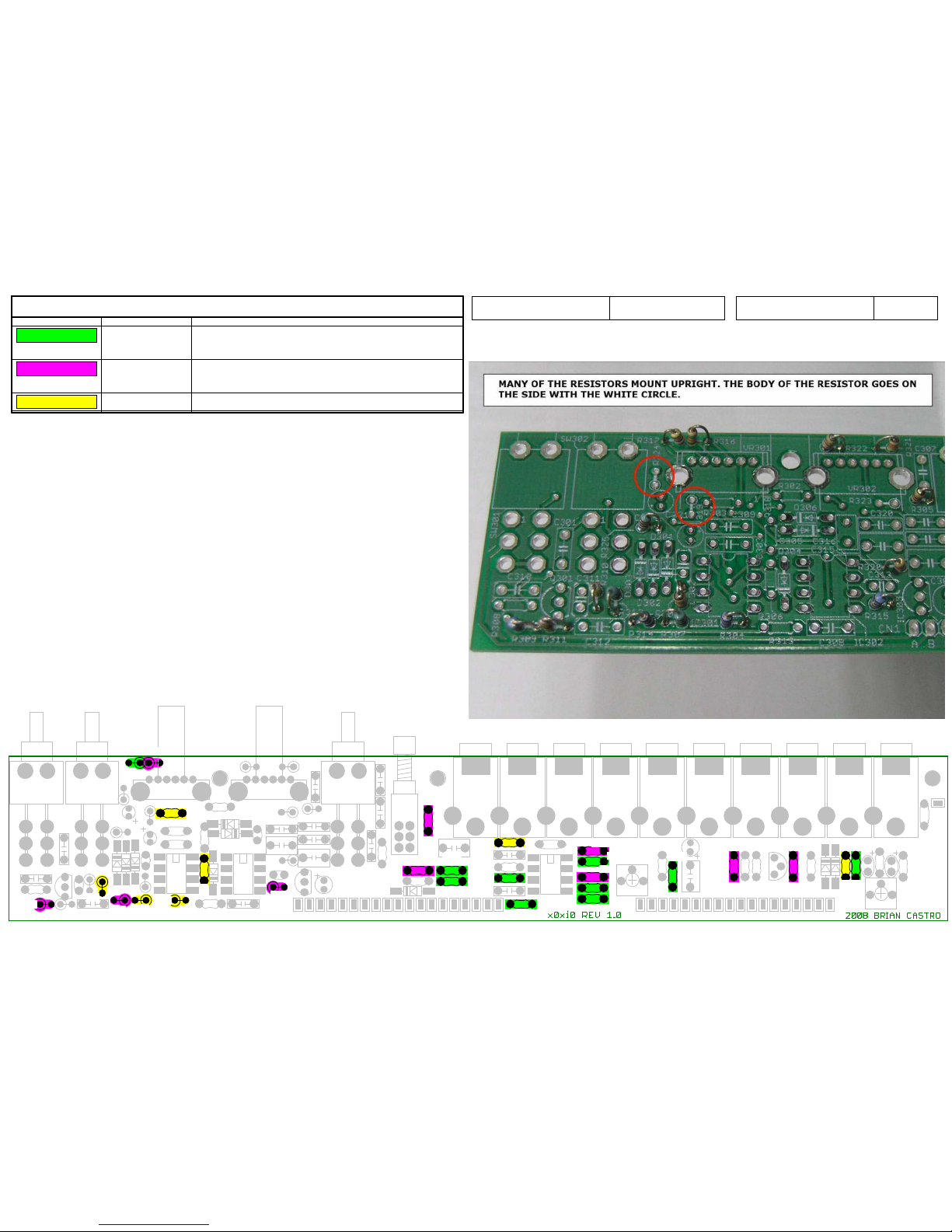
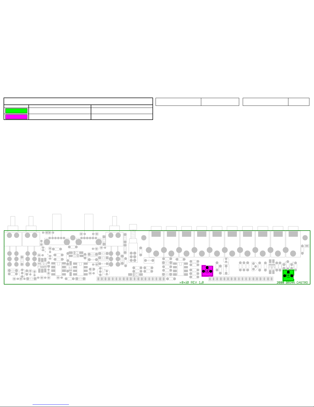
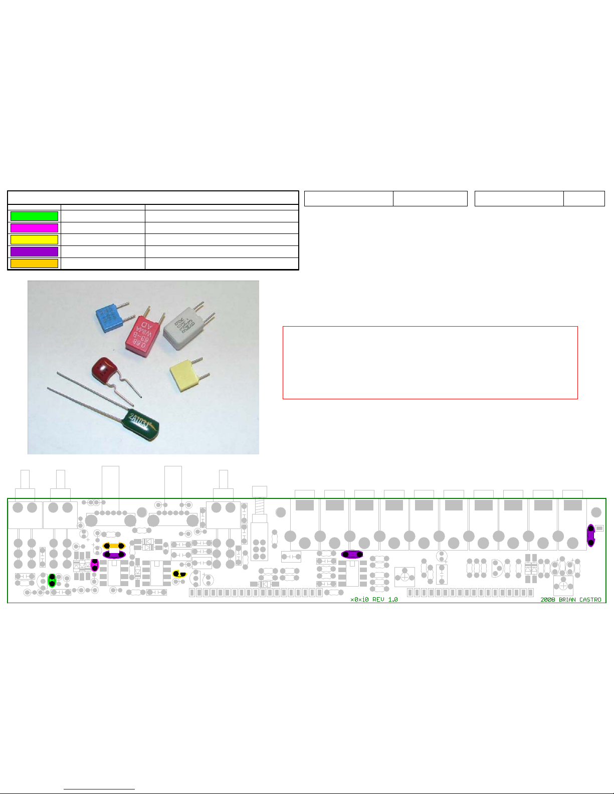
The parts-highlighting-system this document uses should make it a little easier to find the correct locations for all PCB components. Work through each page, installing the
devices listed on each page until all components are fitted. Take note of any special instructions and pictures.
Any multi-instruction pages should be followed in the order - Top left, Bottom left, Top right, Bottom right.
OVERVIEW
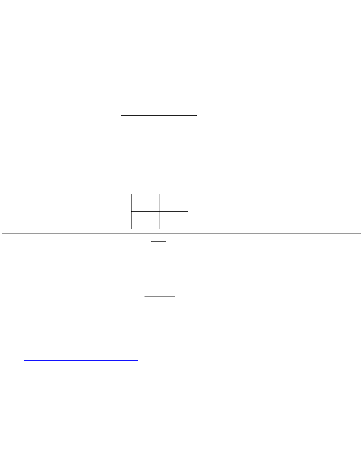
Resistor colour codes:-
It is recommended to check resistor values before fitting.
Ladyada's website is a great resource:-
http://www.ladyada.net/library/metertut/resistance.html
Introduction
Tools
Soldering Iron
Solder
Diagonal cutters
Wire stripper
#0 & #00 phillips screwdrivers
De-soldering tool or soldering braid
Multimeter
A good pc board holder will make things go a bit easier. It is not completely necessary but if you have one or have access to one it will help.
60/40 .031” Rosin core solder is recommended. 63/37 or 60/40 no clean solder is also OK. Lead free solder is not recommended.
Stuffing the PCB is straight forward but it is recommended to follow the steps here, it will make things easier in the long run. It will take approx. 3 hours to follow the
steps and stuff the PCB.
Preperation
1
2
3
4

SW301 SW302
SW303
J310 J309 J308 J307 J306 J305 J304 J303 J302 J301
VR301
VR302
IC301
IC302 IC304
TM302
TM301
Q302
SW304
IC303
Q301
C329
C311
C302
C330
C313
C321
C314
C322
C17
R309
R311
R314
R307
R304
R315
R320
R325
R317
R316
R322
R321
R305
R323
R301
R310
R312
R319
R324
D303
D302D301
D304
D307
D308
D309
D306
D305
C310
C327
C306
C315
C304
C305
C320
C308
C323
C319
C317
C318
C307
C301
C328
C312
R308
C303
C309
R303
R302
R341
C324 R337
R336
R335
R334
R333
R339
C325
R345
R346
R347
R344
R340
R338
C326
R313
R318
R349
R343
R342
R350
R326
R328
R327
R329
R351
R348
R306
C316
R330
R331
R332
FIX2
FIX1 FIX3
A
B
C
C
D
E
F
G
H
I
I
C
C
J K
L
M
N
N
O
C
P
Q
R
S
T
U
U
V
V
W
X
Y
Z
AA
D
C
BB
Diodes
Color Part Number Reference
1N4148
D301-D307, D309
1N5237
D308
1.06Instruction Ver.x0xioProduct Name

SW301 SW302
SW303
J310
J309
J308
J307
J306
J305
J304
J303
J302
J301
VR301
VR302
IC301
IC302 IC304
TM302
TM301
Q302
SW304
IC303
Q301 C329
C311
C302
C330
C313
C321
C314
C322
C17
R309
R311
R314
R307
R304
R315
R320
R325
R317
R316
R322
R321
R305
R323
R301
R310
R312
R319
R324
D303
D302D301
D304
D307
D308
D309
D306
D305
C310
C327
C306
C315
C304
C305
C320
C308
C323
C319
C317
C318
C307
C301
C328
C312
R308
C303
C309
R303
R302
R341
C324 R337
R336
R335
R334
R333
R339
C325
R345
R346
R347 R344
R340
R338
C326
R313
R318
R349
R343
R342
R350
R326
R328
R327
R329
R351
R348
R306
C316
R330
R331
R332
FIX2
FIX1
FIX3
A
B
C
C
D
E F
G
H
I
I
C
C
J
K
L
M
N
N
O
C
P
Q
R
S
T
U
U
V
V
W
X
Y
Z
AA
D
C
BB
Resistors
Color Part Number Reference
2.2k_1/8W
R320-R321, R327
1k_1/8W
R318, R324-R325, R346
6.8k_1/8W
R322-R323
1M_1/8W
R301, R308
47k_1/8W
R313, R331
Product Name x0xio Instruction Ver. 1.06

SW301
SW302
SW303
J310 J309 J308 J307 J306 J305 J304 J303 J302 J301
VR301
VR302
IC301
IC302 IC304
TM302
TM301
Q302
SW304
IC303
Q301
C329
C311
C302
C330
C313
C321
C314
C322
C17
R309
R311
R314
R307
R304
R315
R320
R325
R317
R316
R322
R321
R305
R323
R301
R310
R312
R319
R324
D303
D302D301
D304
D307
D308
D309
D306
D305
C310
C327
C306
C315
C304
C305
C320
C308
C323
C319
C317
C318
C307
C301
C328
C312
R308
C303
C309
R303
R302
R341
C324 R337
R336
R335
R334
R333
R339
C325R345
R346
R347 R344
R340
R338
C326
R313
R318
R349
R343
R342 R350
R326
R328
R327
R329
R351
R348
R306
C316
R330
R331
R332
FIX2
FIX1
FIX3
A
B
C
C
D
E
F
G
H
I
I
C
C
J K
L
M
N
N
O
C
P
Q
R
S
T
U
U
V
V
W
X
Y Z AA
D
C
BB
Resistors
Color Part Number Reference
22k_1/8W
R317, R326, R333-R334, R336, R338-R339,
R343-R345
100k_1/8W
R309, R314-R316, R329, R332, R335, R337,
R347, R349
10k_1/8W
R303-R304, R306-R307, R312, R328, R341
Product Name x0xio Instruction Ver. 1.06

SW301
SW302
SW303
J310
J309
J308
J307
J306
J305
J304
J303
J302
J301
VR301
VR302
IC301
IC302 IC304
TM302
TM301
Q302
SW304
IC303
Q301 C329
C311
C302
C330
C313
C321
C314
C322
C17
R309
R311
R314
R307
R304
R315
R320
R325
R317
R316
R322
R321
R305
R323
R301
R310
R312
R319
R324
D303
D302D301
D304
D307
D308
D309
D306
D305
C310
C327
C306
C315
C304
C305
C320
C308
C323
C319
C317
C318
C307
C301
C328
C312
R308
C303
C309
R303
R302
R341
C324 R337
R336
R335
R334
R333
R339
C325
R345
R346
R347 R344
R340
R338
C326
R313
R318
R349
R343
R342
R350
R326
R328
R327
R329
R351
R348
R306
C316
R330
R331
R332
FIX2
FIX1
FIX3
A
B
C
C
D
E F
G
H
I
I
C
C
J
K
L
M
N
N
O
C
P
Q
R
S
T
U
U
V
V
W
X
Y Z AA
D
C
BB
Resistors
Color Part Number Reference
22_Ohm_1/8W
R311
150_Ohm_1/8W
R350
470_Ohm_1/8W
R305
1.24k_1/8W
R351
3.3k_1/8W
R302
Product Name x0xio Instruction Ver. 1.06

SW301
SW302
SW303
J310
J309
J308
J307
J306
J305
J304
J303
J302
J301
VR301
VR302
IC301
IC302 IC304
TM302
TM301
Q302
SW304
IC303
Q301 C329
C311
C302
C330
C313
C321
C314
C322
C17
R309
R311
R314
R307
R304
R315
R320
R325
R317
R316
R322
R321
R305
R323
R301
R310
R312
R319
R324
D303
D302D301
D304
D307
D308
D309
D306
D305
C310
C327
C306
C315
C304
C305
C320
C308
C323
C319
C317
C318
C307
C301
C328
C312
R308
C303
C309
R303
R302
R341
C324 R337
R336
R335
R334
R333
R339
C325
R345
R346
R347 R344
R340
R338
C326
R313
R318
R349
R343
R342
R350
R326
R328
R327
R329
R351
R348
R306
C316
R330
R331
R332
FIX2
FIX1
FIX3
A
B
C
C
D
E F
G
H
I
I
C
C
J
K
L
M
N
N
O
C
P
Q
R
S
T
U
U
V
V
W
X
Y Z AA
D
C
BB
Resistors
Color Part Number Reference
4.7k_1/8W
R319
15k_1/8W
R348
33k_1/8W
R330
150k_1/8W
R342
220k_1/8W
R340
470k_1/8W
R310
Product Name x0xio Instruction Ver. 1.06

SW301
SW302
SW303
J310 J309 J308 J307 J306 J305 J304 J303 J302 J301
VR301
VR302
IC301 IC302 IC304
TM302
TM301
Q302
SW304
IC303
Q301
C329
C311
C302
C330
C313
C321
C314
C322
C17
R309
R311 R314 R307
R304 R315
R320
R325
R317
R316
R322
R321
R305
R323
R301
R310
R312
R319
R324
D303
D302D301
D304
D307 D308
D309
D306
D305
C310
C327
C306
C315
C304
C305
C320
C308
C323
C319
C317
C318
C307
C301
C328
C312
R308
C303
C309
R303
R302
R341 C324 R337
R336
R335
R334
R333
R339
C325R345
R346
R347 R344 R340
R338
C326
R313
R318
R349
R343
R342 R350
R326
R328
R327
R329
R351
R348
R306
C316
R330
R331
R332
FIX2
FIX1
FIX3
A
B C
CDE
F
G
H I I C C J K
L
M N N
O
C P
Q
R S
T
U U
V
V
W X
Y
Z
AA
D C
BB
Trimmers
Color Part Number Reference
100_TRIMPOT
TM302
20K_TRIMPOT
TM301
1.06Instruction Ver.x0xioProduct Name

SW301
SW302
SW303
J310 J309 J308 J307 J306 J305 J304 J303 J302 J301
VR301
VR302
IC301 IC302 IC304
TM302
TM301
Q302
SW304
IC303
Q301
C329
C311
C302
C330
C313
C321
C314
C322
C17
R309
R311 R314 R307
R304 R315
R320
R325
R317
R316
R322
R321
R305
R323
R301
R310
R312
R319
R324
D303
D302D301
D304
D307 D308
D309
D306
D305
C310
C327
C306
C315
C304
C305
C320
C308
C323
C319
C317
C318
C307
C301
C328
C312
R308
C303
C309
R303
R302
R341 C324 R337
R336
R335
R334
R333
R339
C325R345
R346
R347 R344 R340
R338
C326
R313
R318
R349
R343
R342 R350
R326
R328
R327
R329
R351
R348
R306
C316
R330
R331
R332
FIX2
FIX1
FIX3
A
B C
CDE
F
G
H I I C C J K
L
M N N
O
C P
Q
R S
T
U U
V
V
W X
Y
Z
AA
D C
BB
Ceramic Caps
Color Part Number Reference
270pF_CERAMIC
C311
47pF_CERAMIC
C302
100pF_CERAMIC
C313
0.1uF_CERAMIC
C303, C324, C328
680pF_CERAMIC
C309
The ceramic capacitors also have their value marked on
them. The (3) 0.1uF ceramics have 5mm spacing and
say 104 on them. The rest of them have 3mm spacing.
The 47pF is marked 470, the 270pF is marked 271, and
the 100pF is marked 101.
1.06Instruction Ver.x0xioProduct Name

SW301
SW302
SW303
J310 J309 J308 J307 J306 J305 J304 J303 J302 J301
VR301
VR302
IC301 IC302 IC304
TM302
TM301
Q302
SW304
IC303
Q301
C329
C311
C302
C330
C313
C321
C314
C322
C17
R309
R311 R314 R307
R304 R315
R320
R325
R317
R316
R322
R321
R305
R323
R301
R310
R312
R319
R324
D303
D302D301
D304
D307 D308
D309
D306
D305
C310
C327
C306
C315
C304
C305
C320
C308
C323
C319
C317
C318
C307
C301
C328
C312
R308
C303
C309
R303
R302
R341 C324 R337
R336
R335
R334
R333
R339
C325R345
R346
R347 R344 R340
R338
C326
R313
R318
R349
R343
R342 R350
R326
R328
R327
R329
R351
R348
R306
C316
R330
R331
R332
FIX2
FIX1
FIX3
A
B C
CDE
F
G
H I I C C J K
L
M N N
O
C P
Q
R S
T
U U
V
V
W X
Y
Z
AA
D C
BB
ICs and Transistors
Color Part Number Reference
OP275
IC301-IC302
TLC2272
IC304
TLE2426
IC303
2N5088
Q301
BC549B
Q302
1.06Instruction Ver.x0xioProduct Name

SW301
SW302
SW303
J310 J309 J308 J307 J306 J305 J304 J303 J302 J301
VR301
VR302
IC301
IC302
IC304
TM302
TM301
Q302
SW304
IC303
Q301
C329
C311
C302
C330
C313
C321
C314
C322
C17
R309
R311
R314
R307
R304
R315
R320
R325
R317
R316
R322
R321
R305
R323
R301
R310
R312
R319
R324
D303
D302D301
D304
D307 D308
D309
D306
D305
C310
C327
C306
C315
C304
C305
C320
C308
C323
C319
C317
C318
C307
C301
C328
C312
R308
C303
C309
R303
R302
R341 C324 R337
R336
R335
R334
R333
R339
C325R345
R346
R347 R344 R340
R338
C326
R313
R318
R349
R343
R342
R350
R326
R328
R327
R329
R351
R348
R306
C316
R330
R331
R332
FIX2
FIX1
FIX3
A
B C
CDE
F
G
H I I C C J K
L
M N N
O
C P
Q
R S
T
U U
V
V
W X
Y
Z
AA
D C
BB
Polyester Caps
Color Part Number Reference
68nF_POLYESTER
C310
1.0uF_POLYESTER
C323, C327
0.47uF_POLYESTER
C306, C315
33nF_POLYESTER
C304
47nF_POLYESTER
C305, C312
82nF_POLYESTER
C320
18nF_POLYESTER
C308, C318
56nF_POLYESTER
C319
22nF_POLYESTER
C301, C317
27nF_POLYESTER
C307
0.1uF_POLYESTER
C325-C326
33nF_(RED)_POLYESTER
C316
There are several different kinds of capacitors in the kit. The polyester caps
deserve special attention since there may be several different colors in the kit.
Your kit will most likely include a few of the types shown in the picture below.
The red, yellow, white, and blue rectangle ones are polyester box caps. The
other red and green ones are dipped polyester. The majority of them will be
the yellow box type – but there also may be some of the other colors. They are
all equivalent – just made by different manufacturers. The value is shown on
the part, usually indicated in nF (nanofarads). For example 10n = 10nF, 470n
= 470nF. In some cases they may say 0.1 = 0.1uF = 100nF or 1u0 = 1uF. The
letter J or K simply indicates the tolerance of the part, 5% or 10%.
1.06Instruction Ver.x0xioProduct Name

SW301 SW302
SW303
J310
J309
J308
J307
J306
J305
J304
J303
J302
J301
VR301
VR302
IC301 IC302 IC304
TM302
TM301
Q302
SW304
IC303
Q301
C329
C311
C302
C330
C313
C321
C314
C322
C17
R309
R311
R314
R307
R304
R315
R320
R325
R317
R316
R322
R321
R305
R323
R301
R310
R312
R319
R324
D303
D302D301
D304
D307
D308
D309
D306
D305
C310
C327
C306
C315
C304
C305
C320
C308
C323
C319
C317
C318
C307
C301
C328
C312
R308
C303
C309
R303
R302
R341
C324 R337
R336
R335
R334
R333
R339
C325R345
R346
R347 R344
R340
R338
C326
R313
R318
R349
R343
R342
R350
R326
R328
R327
R329
R351
R348
R306
C316
R330
R331
R332
FIX2
FIX1
FIX3
A
B
C
C
D
E
F
G
H
I
I
C
C
J K
L
M
N
N
O
C
P
Q
R
S
T
U
U
V
V
W
X
Y Z AA
D
C
BB
Electrolytic Caps
Color Part Number Reference
4.7uF_ELECTROLYTIC
C321
1.0uF_ELECTROLYTIC
C17, C314
22uF_ELECTROLYTIC
C322
1.06Instruction Ver.x0xioProduct Name

SW301
SW302
SW303
J310 J309 J308 J307 J306 J305 J304 J303 J302 J301
VR301
VR302
IC301
IC302 IC304
TM302
TM301
Q302
SW304
IC303
Q301
C329
C311
C302
C330
C313
C321
C314
C322
C17
R309
R311
R314
R307
R304
R315
R320
R325
R317
R316
R322
R321
R305
R323
R301
R310
R312
R319
R324
D303
D302D301
D304
D307 D308
D309
D306
D305
C310
C327
C306
C315
C304
C305
C320
C308
C323
C319
C317
C318
C307
C301
C328
C312
R308
C303
C309
R303
R302
R341
C324 R337
R336
R335
R334
R333
R339
C325
R345
R346
R347 R344 R340
R338
C326
R313
R318
R349
R343
R342
R350
R326
R328
R327
R329
R351
R348
R306
C316
R330
R331
R332
FIX2
FIX1
FIX3
A
B
C
CDE
F
G
H
I
I
C
C
J
K
L
M
N
N
O
C
P
Q
R
S
T
U
U
V
V
W
X
Y
Z
AA
D
C
BB
Tantalum Caps
Color Part Number Reference
1.0uF_TANTALUM
C329
10uF_TANTALUM
C330
It must be noted that if you have a kit with serial number 1
through 42 the silkscreen legend for part C330 is incorrect.
The (+) side of the cap goes towards the top of the PCB,
not towards the bottom as indicated on the PCB!
1.06Instruction Ver.x0xioProduct Name

SW301 SW302
SW303
J310 J309 J308 J307 J306 J305 J304 J303 J302 J301
VR301
VR302
IC301 IC302
IC304
TM302
TM301
Q302
SW304
IC303
Q301 C329
C311
C302
C330
C313
C321
C314
C322
C17
R309
R311
R314
R307
R304
R315
R320
R325
R317
R316
R322
R321
R305
R323
R301
R310
R312
R319
R324
D303
D302D301
D304
D307 D308
D309
D306
D305
C310
C327
C306
C315
C304
C305
C320
C308
C323
C319
C317
C318
C307
C301
C328
C312
R308
C303
C309
R303
R302
R341
C324 R337
R336
R335
R334
R333
R339
C325
R345
R346
R347 R344 R340
R338
C326
R313
R318
R349
R343
R342
R350
R326
R328
R327
R329
R351
R348
R306
C316
R330
R331
R332
FIX2
FIX1
FIX3
A
B C
C
D
E F
G
H I I C C J K
L
M N N
O
C
P
Q
R S
T
U
U
V
V
W
X
Y
Z
AA
D C
BB
Jacks, Switches and Pots
Color Part Number Reference
JACK_SOCKET
J301-J310
1.06Instruction Ver.x0xioProduct Name

Jacks, Switches and Pots
You may want to test fit the rear panel to
make sure they are aligned good enough.
Next you can solder the rear solder pad for each of the jacks.
Make sure the jack is seated properly before soldering. Hold
down the jack firmly while soldering so that it seats properly.
Next you can go back and re-heat the front pads and add more solder,
then solder in the third pad for each jack and everything should look ok.
Now is a good time to clean your PCB. If you’re using ordinary 60/40
rosin core solder you probably have a lot flux residue. Cleaning pcb’s
is a whole art form in itself. Your best bet is to use a flux remover
spray or denatured alcohol and a brush. A boar’s hair brush is what is
typically used.
Install the (3) small L-brackets to the PCB as shown. Use the 11/32”
4-40 screws. There’s an extra screw in the package that can be used to
help align the bracket while the nut is tightened. Position the L-brackets
so that the screw is going through the unthreaded hole. The threaded
hole is used later to mount the PCB assembly to the rear panel.
1.06Instruction Ver.x0xioProduct Name
1.
2.
3.
4.
IMPORTANT:-
Make sure not to
over-tighten the screw that
mounts the middle
L-bracket to the PCB,
there is a trace that runs
underneath that screw and
if it is over-tightened it may
scratch through the
soldermask and short that
trace to ground.

SW301 SW302
SW303
J310 J309 J308 J307 J306 J305 J304 J303 J302 J301
VR301
VR302
IC301 IC302
IC304
TM302
TM301
Q302
SW304
IC303
Q301 C329
C311
C302
C330
C313
C321
C314
C322
C17
R309
R311
R314
R307
R304
R315
R320
R325
R317
R316
R322
R321
R305
R323
R301
R310
R312
R319
R324
D303
D302D301
D304
D307
D308
D309
D306
D305
C310
C327
C306
C315
C304
C305
C320
C308
C323
C319
C317
C318
C307
C301
C328
C312
R308
C303
C309
R303
R302
R341
C324 R337
R336
R335
R334
R333
R339
C325
R345
R346
R347 R344 R340
R338
C326
R313
R318
R349
R343
R342
R350
R326
R328
R327
R329
R351
R348
R306
C316
R330
R331
R332
FIX2
FIX1
FIX3
A
B C
C
D
E F
G
H I I C C J K
L
M N N
O
C
P
Q
R S
T
U
U
V
V
W
X
Y
Z
AA
D C
BB
Jacks, Switches and Pots
Color Part Number Reference
DPDT_PUSH
SW304
Install the push switch. Solder one pin first and make sure
you have it aligned and seated properly before soldering
all the pins. Put the switch cap on and check alignment
against the rear panel before soldering all the pins.
1.06Instruction Ver.x0xioProduct Name

SW301
SW302
SW303
J310 J309 J308 J307 J306 J305 J304 J303 J302 J301
VR301
VR302
IC301 IC302
IC304
TM302
TM301
Q302
SW304
IC303
Q301
C329
C311
C302
C330
C313
C321
C314
C322
C17
R309
R311
R314
R307
R304
R315
R320
R325
R317
R316
R322
R321
R305
R323
R301
R310
R312
R319
R324
D303
D302D301
D304
D307
D308
D309
D306
D305
C310
C327
C306
C315
C304
C305
C320
C308
C323
C319
C317
C318
C307
C301
C328
C312
R308
C303
C309
R303
R302
R341
C324 R337
R336
R335
R334
R333
R339
C325
R345
R346
R347 R344 R340
R338
C326
R313
R318
R349
R343
R342 R350
R326
R328
R327
R329
R351
R348
R306
C316
R330
R331
R332
FIX2
FIX1
FIX3
A
B C
C
D
E
F
G
H I I C C J K
L
M N N
O
C
P
Q
R S
T
U
U
V
V
W
X
Y
Z
AA
D C
BB
Jacks, Switches and Pots
Color Part Number Reference
DPDT_TOGGLE_(ON-NONE-ON)
SW301-SW302
DPDT_TOGGLE_(ON-OFF-ON)
SW303
Install the toggle switches. Begin by soldering in the front two pins and align the
switch properly before soldering the remaining pins. You can use the rear panel
to verify alignment if you need to.
1.06Instruction Ver.x0xioProduct Name

SW301 SW302
SW303
J310
J309
J308
J307
J306
J305
J304
J303
J302
J301
VR301
VR302
IC301 IC302
IC304
TM302
TM301
Q302
SW304
IC303
Q301 C329
C311
C302
C330
C313
C321
C314
C322
C17
R309
R311
R314
R307
R304
R315
R320
R325
R317
R316
R322
R321
R305
R323
R301
R310
R312
R319
R324
D303
D302D301
D304
D307
D308
D309
D306
D305
C310
C327
C306
C315
C304
C305
C320
C308
C323
C319
C317
C318
C307
C301
C328
C312
R308
C303
C309
R303
R302
R341
C324 R337
R336
R335
R334
R333
R339
C325
R345
R346
R347 R344 R340
R338
C326
R313
R318
R349
R343
R342
R350
R326
R328
R327
R329
R351
R348
R306
C316
R330
R331
R332
FIX2
FIX1
FIX3
A
B C
C
D
E F
G
H I I C C J K
L
M N N
O
C
P
Q
R S
T
U
U
V
V
W
X
Y
Z
AA
D C
BB
Jacks, Switches and Pots
Color Part Number Reference
1MA_POT
VR301
10KB_POT
VR302
1.06Instruction Ver.x0xioProduct Name

IC305
Solder in IC305, the voltage regulator. NOTE: This
component is mounted from the bottom side of the
pcb! Bend it a bit so that it angles away from the PCB:
Product Name x0xio Instruction Ver. 1.06

x0xio Installation Product Name x0xio Instruction ver 1.06
Preparation
- Strain relief for CPU lines: It is a good idea to make sure you have some sort of strain
relief for the (12) wires of J3 on the x0xb0x mainboard & I/O board. If there’s stress on any
one or more of these wires at either side they will most likely tear loose from stress after
flipping the PCB’s upside-down over and over again while installing the kit. The other
jumpers can a
lso become stressed so look out for those too. There is a chance you will
need to re-connect some of these wires if they break loose.
- There is more than enough wire included to complete the installation. I would recommend
using the colors as described in the steps. Make sure to cut the wires to the lengths stated,
if you make them shorter you may not have enough length to properly reassemble the
x0xb0x.
- There are many connections to the x0xb0x where a wire is soldered to the solder pad of a
resistor or transistor. Below is the pin configuration for all of the x0xb0x transistors:
- Whenever a wire is soldered to a solder pad shared by a resistor it is done on the wire
lead side of the resistor, not the body side of the resistor. This makes it much easier to
solder to the pad. After working on several x0xb0x’s I have seen several instances where
the resistors are soldered in backwards. This is generally not a problem but since you will
now be soldering an extra wire to some of the resistor pads the
body of the resistor may get
in the way if the resistor was installed backwards. In these cases you may need to remove
the resistor and re-solder it the correct way:
I’ve also worked on several x0xb0x’s where the resistors are installed horizontal with the
legs bent under them. If your x0xb0x is like this you may need to replace those resistors if
there isn’t good access:
Table of contents