manuals.online logo
Brands
  1. Home
  2. •
  3. Brands
  4. •
  5. Xpelair
  6. •
  7. Fan
  8. •
  9. Xpelair PX12 User manual

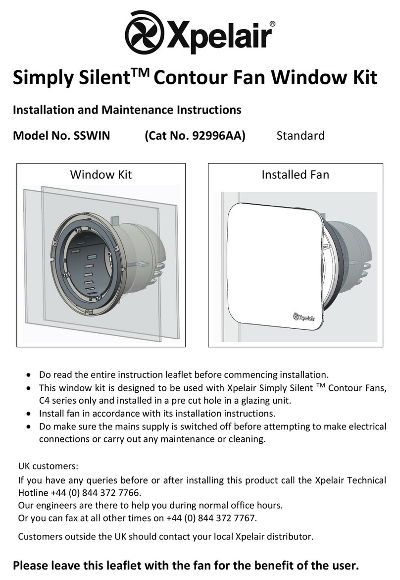
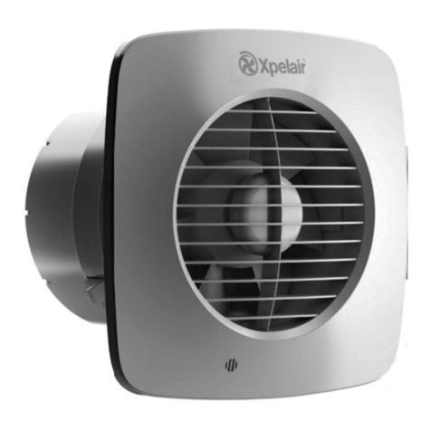
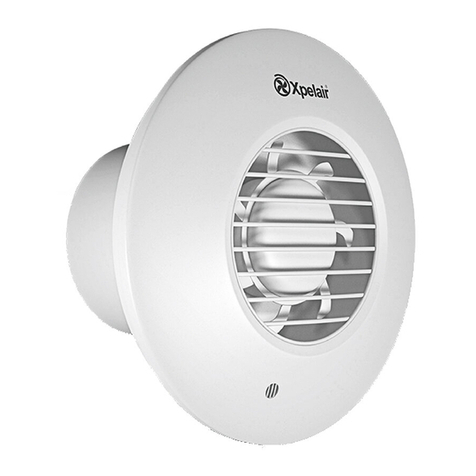
Xpelair PX12 User manual

• Do read the entire instruction leaflet before commencinginstallation.
• Do install each fan with a double pole-isolating switch.
• Do make sure the mains supply is switchedoffbefore attemptingtomake electrical
connections or carry outanymaintenanceor cleaning
Customers outside UK – see international below.
•UK: The fan is guaranteed against defects for 2 years from the date of purchase.
• Please keep your purchase receipt.
•If you have anyproblems, contact Xpelair’s HeadOffice at the address shown below.
Customers outside UK – see international below.
UK: Xpelair haveacomprehensive range of services including:
• Free technical advice help-deskfrom Engineers on all aspects of ventilation
•Free design service, quotations andsite surveys
•Service and maintenance contracts tosuitall requirements.
Please askfordetails:
• Bytelephone onTechline:+44 (0)8709 000430
• Byfax on Techfax:+44(0) 8709 000530
•At the address below
•Guarantee: Contact your localdistributor or Xpelair directfor details.
• TechnicalAdvice and Service: Contact your localXpelair distributor
Do’s and don’ts
Guarantee
Technicaladvice and service
International
Applied Energy Products Ltd
Morley Way
Peterborough
PE2 9JJ
t 01733 456789
f 01733 310606
www.applied
-energy.com
Xpelair is aregistered trademark of Applied Energy Products Limited.
Applied EnergyProducts reserve the right toalterproduct specifications
or appearancewithout prior notice.
All finishes and diagrams inthis booklet areas accurateas printing
processes allow.
(Booklet No.
22721AA)
PX6, PX9 and PX12 Commercial ceilingfans
Installation and maintenance instructions
2
7
H
G2
G1
6
3
Installing the Fan
These appliances are intended for connection tofixed wiring.
Checkthat the electrical rating shown on the fan matches the mains supply.
WARNING:THESE APPLIANCES MUST BE EARTHED.
All installationsmust be supervised bya qualified electrician.
Installations and wiring must conform tocurrent IEE Regulations (UK), local or
appropriate regulations(other countries). It is the installer’sresponsibilitytoensure that
the appropriate Building Codes of Practiceare adhered to.
If you haveanyqueries before installingthese products or after theyhavebeen installed,
call theXpelairTechnical Hotline +44 (0) 8709 000430. Our engineers are there tohelp
you during normal office hours (UKonly)and maybe faxed at all other times +44 (0) 8709
000530.
Customers outside the UK pleasecontact yourlocal Xpelair distributor.
1. Description
The PX6/9/12 models have the followingfeatures:
• Can be flush mountedin a Ceilingor Panel.
• Trickle ventilation setting.
• Fitted with silent operation back draughtshutters.
• For remote switch operation.
PX6
• Single speed extract operation.
PX9/12
• The PX9/12 fans can extract, intake or ‘open shutter only’ usingan integral Fanselector
switch.
• Can be installed with a controller.
If used with a speed controller, thesefans can intakeor extract at selected speeds or atvariable
speeds depending on thetypeof controller. If used with an on/off switch, thesefans will intake
or extractat high speed only.
2. What the installer will need
• Adouble pole isolatingswitch with a minimum contact gap of 3mm (Ceilingor Panel
mounted).
• If metalswitch boxes are used, earthing regulations must be followed.
• Suitablyrated 3-core cable (see ‘Installingswitchesand cables’ section).
• 6mm blade largescrewdriver, 3mm blade electrician’s screwdriver and No. 1 & 2 Pozidriv
screwdrivers.
If installingthe fan with anon/off switch:
• On/Off switch
If installingthe fan with a controller (PX9/12 only):
• Suitablyrated 5-core cable. Note:Please check instructions for the controller.
3. Where to locate the fan
• Locateit as high as possible.
If installing a PX6:
• Atleast 200mm from the edge of the wall or ceilingtothe centre of the hole.
If installing a PX9:
• Atleast 255mm from the edge of the wall or ceilingtothe centre of the hole.
If installing a PX12:
• Atleast 280mm from the edge of the wall or ceilingtoth e centre of the hole.
• Asfarawayas possiblefrom and opposite tothe main source of air replacementtoensure
airflow across the room (e.g. opposite the internal doorway).
• Near the source of steam or odours.
• Not where ambienttemperatures are likelytoexceed 50°C.
• If installed in a kitchen, fans must not be mounted immediatelyabove a cooker hob or
eye level grill.
• If installing ina room containing a fuel-burning device which has a non-balanced flue, it
is the installer’s responsibilityto ensure thatthere is enough replacement airtoprevent
fumes being drawn down the flue when thefan is operatinguptomaximum extract.
Refer toBuildingRegulations for specific requirements.
Exhaust air must not be discharged intoa flue used for exhau sting fumes from appliances
supplied with energyother thanelectric.
Requirements of all authorities concerned mustbe observed for exhaust airdischarge and
intake flow rates.
• If the fanis intended tointakeair, the inletgrille shouldbesited at a distance of at least
0.5 meters from the discharge outlet of a flued heating or cooking appliance.
• When intended for use in possible chemicalcorrosiveatmospheres, consult our Technical
Service Department. (Foroverseas market contact your local Xpelai r distributor).
• This electricalproduct, if installed in a shower room or bathroom must be situated so
that itcannotbe touched bypersons making use of the bathor shower.
4. Installingthe switches andcables
1. Checkthere are noburiedpipes or cables e.g. electricity, gas, water behind the switch
location (In the panel or abovethe ceiling).
2. Layin the cable from the isolatingswitch tothe fan location via the on/off or controller if
required.
3. Layin the cable from the isolatingswitch tothe point of connection tothe mains supply.
WARNING:DONOT MAKE ANY CONNECTIONS TO THE ELECTRICAL SUPPLY
AT THIS STAGE.
4. Install the isolatingswitch and the on/off switch or controller if required.
5. Make allconnections within the isolatingsw itch and the on/off switch if required.
Note: Switches must be sosituated that theycannot be touched bypersonsmakinguse of
the bath or shower.
For Australia only
These models are permanentlyconnected tothe supplyand operation is controlledbya remote
switch. Theyshouldbe directlywired tothe supplythrough an approved 10Awall mounted
surface switch with at least3mm clearance between contacts.
5. Preparing the hole
If working above ground floor level, appropriate safetyprecautions must be observed.
WARNING: EYE PROTECTION MUST BE WORN DURINGALL DRILLING
OPERATIONS.
For Installing ina panel /ceiling
1. Checkthere arenoburied pipes or cablesbehind the panelor obstructions on the
outside e.g. electricity, gas, water.
If installingaPX6:
2a. Make sure that the centre of the hole is located at least 200mm from the edge of the wall or
ceiling.
If installingaPX9:
2b. Make sure that the centre of the hole is located at least 255mm from the edge of the wall or
ceiling.
If installing aPX12:
2c. Make surethat the centre of the hole is located at least280mm from the edge of the wall or
ceiling.
3. Mark the outline of the hole on the wall (for hole dimensions see FigA ).
4. Drillpilot holes around edge of the cuttingline.
5. Cut through the panel or ceilingusinga jigsaw.
6. Separating the inner grille andfan from mounting box
If installingaPX6:
1. Removethe inner grille assemblybyremovingthe 2 screws G1 (8) securingthe inner grille
assemblytothe fan mountingbox.
2. Removethe twoscrews securingthe fan assemblytothe fan mountingbox.
If installingaPX9/12:
1. Removethe inner grille byremovingthe 4 screws G2 (8).
2. Removethe back draught shutter byunclippingit G2 (5).
3. Unscrew the 4 cross-headed screws and lift off the fan assemblyG2 (2)
7. Mounting the fanmounting box.
If working above ground floor level, appropriate safetyprecautions must be observed.
1. Offer up the fan mountingbox tothe panelor ceilingface andmark the position of the 4
mountingholes.
2. Drillholes and fit appropriate plugs.
3. Screw fan mountingbox topanel or ceiling(If necessaryapplya sealingmastictothe flanges
of the fan mountingbox. This will provide additional seals and takeout anyunevenness on both
faces).
4. Ductingand appropriate terminations can be attached tothe fan box as required.
5. Position and secure the fan duct assemblyintothe fan mountingbox, usingthe fixingscrews .
Donot overtighten the screws.
8. Wire the electrical connections
If installingaPX6:
1.Wire theswitch cable intothe fan’s terminalconnector as shown indiagram B2.
2a. If the Fan iswired from above, remove the fan’sTerminal cover and feed the cablethrough
the top cable entry. Ensure the outer sheathof the cableis retained in the labyrinth B1.
2b. If wiringfrom the rear, remove thefan’s terminalcover and rear entryknockout, feed the
cable through the knockout.
3. Refit and secure the terminal cover.
4. Refit the inner grille tothefanmountingbox, usingfixi ngscrews G1 (8). Donot overtighten
screws.
5. Insert two colour matchingscrew covers in the fixingholes in the inner grille. When
removingthe covers, place a 3mm blade electrician’s screwdriver intothe slotand lever off the
cover.
6. Switch off the mains electrical supplyandremove fuses.
7. Connect the cable from isolationswitch tothe electrical supplywiring.
8. Replace thefuses, and switch on the mains electrical supply.
Forfixed wiring circuitsthe protective fuse forthe appliance must n ot exceed 5A.
If installingaPX9/12:
1. The fan connector parts arepacked separately.
2. Removethe twocable clamp screws (fig. C1 and C2).
3. If required feed the cable through thegrommet in order tofit the cable entryof theconnector
plate.
• If installing with an on/offswitch:
1. Wire the fan connector as shown in fig. B3
2. Set the Fan Selector Switch toposition 1 for Intake, Position 2 for Extract or Position 3 for
‘open shutter only’ (FigD.)
• If installing with a controller:
1. Refer tothe installationinstructionsfor the controller.
2. If wiringtoan existingcontroller, contact XpelairTechnical Services or in export markets,
the Xpelair distributor
3. Set the Fan selector Switch toposition 3 if usinga controller providingvariable sp eed and/or
direction. Otherwise, setthe Fan Selector Switch toPosition 1for Intake, Position 2 for Extract
or Position 3 for ‘open shutter only’ (fig. D).
Fitting the cable clamp (PX9/12):
For cable up to8mm diameter, clamp the cable as shown in Fig. C (1).
For cable equaltoor greater than 8mm and up to11.5mm diameter, clamp the cable as shown in
Fig. C (2).
For cable greater than 11.5mm diameter use the conduit entryprovided (Europeonly).
Fitting the Connector to the fan(PX9/12):
1. Ensure the cable is firmlyretained bythe clamp.
2. AssemblytheFan Connectorbysnappingthe Cover over the Connector (Fig. E).
3. Plugthe Fan Connector intothe Fan Assembly.
4. Refit the Backdraught Shutter.
5. Refit the Inner Grille.
6. Insertfour screw covers (packed separately) in the fixingholes in the Inner Grille. When
removingthe covers, place a 3mm blade electrician’s screwdriver intothe slot andlever off the
cover.
7. Switch off the mains electrical supplyand remove fuses.
8. Connect the cable from isolation switch tothe electricalsupplywiring.
9. Replace the fuses, and switch on the mains electrical supply.
For fixed wiring circuits theprotective fuse for the appliance must notexceed 5A.
9. Operating the fan
Switch operated:
• Toswitch on and off, use theswitch onthe wall or ceiling.
Controller operated (PX9/12 only):
• Refer tothe instructions for the controller.
• The shutters have a time delayof up to1 minute onopening, andup to3 minutes on closing.
Activated byoperation of the switch, thedelayensures quiet operation.
For Australia only:
WARNING – Children should not playwith theappliance. Youngchildren and the infirm
should be supervised
Trickle ventilation
Trickle ventilation is equivalent tothatprovided byan air brick or similar device.
1. Remove the Inner grille and back draught shutter (see‘Mountingthe fan in the hole ’ section).
To allow trickle ventilation (PX6):
2. HOLD THE SHUTTER VANES FULLY OPEN.
3. Push down firmlyon the trickle vent catch until itclicks intoposition thenrelease the shutter
vanes. (See Fig.F1).
To allow trickle ventilation (PX9/12):
2. Release the ShutterReturn Springas shown inFig. F2
3. Re-Position the Shutter Return Springintothe L -shaped slot.
4. Raise the operatingBar tolatch intoposition.
To fullyclose the shutters and stop any back draught (PX6)
5. Pull the trickle vent catch towards you until it clicks intoposition.
6. Refit the Inner grille and back draught shutter, ensuringthatthe actuator lever is in the “fully
down” position.
To fullyclose the shutters and stop any back draught (PX9/12)
5. Unlatch the Shutter Return Springand re -position intoshort slot.
6. Refit the BackdraughtShutter and Inner Grille.
Maintenance
NOTE: AQUALIFIEDELECTRICIAN MUST CARRY OUT ALLCLEANING.
1. Beforecleaning, isolate the fan completelyfrom the mains supply. Allow 3 minutesfor
the impeller tostop and the powered shutter toclose.
2. Remove the inner grille and back-draught shutter (seesection 6)
WARNING:Fan will still operatewhen the innergrille is removed.
To remove theimpeller (PX6):
3. Unscrew the central screw and remove it together with the washer, Placescrew and washer to
one side G1 (9).
To remove theimpeller (PX9/12):
3. Remove the impellerbyunscrewingthe knob at the frontof the impeller anticlockwise.
4. Clean the back draught shutter, inner grilleand impellerbyimmersingin warmsoapywater.
Drythoroughly.
Donot immerse the fan in water orother liquids toclean anyother parts of the f an.
To refitthe impeller (PX6):
5. Refit the impeller and replace the screw and washer ensuringthat theyaresecurelyfitted.
To refitthe impeller (PX9/12):
5. Refit the impeller bylocatingitover themotor shaftand aligningthe arrow on the impelle r
with thewhite dot on the motor. Make sure the impelleris seated correctly.
6. Refit the knob makingsure the ratchetat the rear of the knob is fullyengaged.
7.Refit the back draughtshutter and inner grille assemblyand secure with the2fixingscre ws.
Donot overtighten the screws.
8. Refit the screw covers.
NOTE: THE FAN WILL CONTINUE TOOPERATE WITH THE INNER GRILLE
ASSEMBLY REMOVED, HENCE IT MUST BE ISOLATED COMPLETELY FROM
THE MAINS BEFORE ANY WORKIS CARRIED OUT.
• Never use strong solventstoclean the fan.
• Apart from cleaning, noother maintenanceis required.
Components
1. Inner Grille 8. Screws (M4 x 10mm long)
2. Fan assembly 9. Impeller screw
3. Fan mountingbox 10. Screws (No.8 x 55mm long)
4. Trickle vent catch 11. Selectorswitch
5. Back draught shutter 12. Customer connector
6. Terminalcover 13. Shutter return spring
7. RatingPlate 14. Operatingbar.
B1
B2
B3
A
PX6
PX9
PX12
4 5
PX6
F2
F1E
C D
1. 2.

This manual suits for next models

2

Other Xpelair Fan manuals

Xpelair WX6 User manual

Xpelair

Xpelair WX6 User manual

Xpelair WX6 User manual

Xpelair

Xpelair WX6 User manual

Xpelair XIL100 User manual

Xpelair

Xpelair XIL100 User manual

Xpelair C6R User manual

Xpelair

Xpelair C6R User manual

Xpelair GX9 and User manual

Xpelair

Xpelair GX9 and User manual

Xpelair Premier DX180H User manual

Xpelair

Xpelair Premier DX180H User manual

Xpelair WX6 User manual

Xpelair

Xpelair WX6 User manual

Xpelair Simply Silent C4S (92960AW) User manual

Xpelair

Xpelair Simply Silent C4S (92960AW) User manual

Xpelair GX12 User manual

Xpelair

Xpelair GX12 User manual

Xpelair DX100 User manual

Xpelair

Xpelair DX100 User manual

Xpelair WX9 User manual

Xpelair

Xpelair WX9 User manual

Xpelair LVCF20 User manual

Xpelair

Xpelair LVCF20 User manual

Xpelair SLDC150 User manual

Xpelair

Xpelair SLDC150 User manual

Xpelair Everdri XEL User manual

Xpelair

Xpelair Everdri XEL User manual

Xpelair Xpelair SL150T User manual

Xpelair

Xpelair Xpelair SL150T User manual

Xpelair CX10 User manual

Xpelair

Xpelair CX10 User manual

Xpelair LV100 and User manual

Xpelair

Xpelair LV100 and User manual

Xpelair AirLine AL100 User manual

Xpelair

Xpelair AirLine AL100 User manual

Xpelair VX100 User manual

Xpelair

Xpelair VX100 User manual

Xpelair XIM100+ User manual

Xpelair

Xpelair XIM100+ User manual

Xpelair Xcell Stratum S120Q User manual

Xpelair

Xpelair Xcell Stratum S120Q User manual

Xpelair LVCF20TX User manual

Xpelair

Xpelair LVCF20TX User manual

Xpelair DX100 User manual

Xpelair

Xpelair DX100 User manual

Xpelair DX100B User manual

Xpelair

Xpelair DX100B User manual

Popular Fan manuals by other brands

Homeworks 7117-01-WH Installation instruction

Homeworks

Homeworks 7117-01-WH Installation instruction

Woods EC BOX FAN SAFETY, INSTALLATION, OPERATION AND MAINTENANCE INSTRUCTIONS

Woods

Woods EC BOX FAN SAFETY, INSTALLATION, OPERATION AND MAINTENANCE INSTRUCTIONS

Vent-Axia MUTE 100 BN Installation and wiring instructions

Vent-Axia

Vent-Axia MUTE 100 BN Installation and wiring instructions

Delta Electronics BFB1212H Dimensions and installation information

Delta Electronics

Delta Electronics BFB1212H Dimensions and installation information

Westinghouse WSFT200A instruction manual

Westinghouse

Westinghouse WSFT200A instruction manual

ResMed Stellar 150 manual

ResMed

ResMed Stellar 150 manual

Manutan A040386 user guide

Manutan

Manutan A040386 user guide

Klarstein SUMMERJAM manual

Klarstein

Klarstein SUMMERJAM manual

Evolution 2408 installation guide

Evolution

Evolution 2408 installation guide

Helios RADAX MV Series Installation and operating instructions

Helios

Helios RADAX MV Series Installation and operating instructions

Harbor Breeze MONTCLAIR E-CM54RBZ5CRCI installation guide

Harbor Breeze

Harbor Breeze MONTCLAIR E-CM54RBZ5CRCI installation guide

Geovent MSQ 200 instruction manual

Geovent

Geovent MSQ 200 instruction manual

KDK SD30H operating instructions

KDK

KDK SD30H operating instructions

Hunter Pacific Typhoon Mach 2 Timber installation manual

Hunter Pacific

Hunter Pacific Typhoon Mach 2 Timber installation manual

Kendal Lighting AC-20152 installation instructions

Kendal Lighting

Kendal Lighting AC-20152 installation instructions

Ryobi RCF18 manual

Ryobi

Ryobi RCF18 manual

Swegon KITE Ceiling manual

Swegon

Swegon KITE Ceiling manual

SCA S160-23-02310 Owner's instruction manual

SCA

SCA S160-23-02310 Owner's instruction manual

manuals.online logo
manuals.online logoBrands
  • About & Mission
  • Contact us
  • Privacy Policy
  • Terms and Conditions

Copyright 2025 Manuals.Online. All Rights Reserved.