Xsens Awinda Station User manual

Synchronising Xsens Systems with
Noraxon TeleMyo
Step –by –step manual
16 –01 –2020
© 2005-2020, Xsens Technologies B.V. All rights reserved. Information in this document is subject to change
without notice. Xsens, MVN, MotionGrid, MTi, MTi-G, MTx, MTw, Awinda and KiC are registered trademarks
or trademarks of Xsens Technologies B.V. and/or its parent, subsidiaries and/or affiliates in The Netherlands,
the USA and/or other countries. All other trademarks are the property of their respective owners.

1
www.xsens.com
Table of Contents
1Synchronization Workflow ........................................................ 2
2Required Hardware ................................................................... 3
3Hardware connections scheme.................................................. 4
4MVN Analyze as Master and as Noraxon TeleMyo slave .............6
4.1 Start and Stop a recording .......................................................................... 6
4.1.1 Hardware connections ........................................................................... 6
4.1.2 Software Setup Noraxon MyoResearch..................................................... 6
4.1.3 Xsens Software..................................................................................... 8
5Noraxon TeleMyo as Master and MVN Analyze as slave ............. 9
5.1 Start and Stop a recording .......................................................................... 9
5.1.1 Hardware connections ........................................................................... 9
5.1.2 Noraxon MyoResearch Software.............................................................. 9
5.1.3 XSens Software ...................................................................................10
6Using the Link System............................................................. 11

2
www.xsens.com
1Synchronization Workflow
The steps described below show how to make it possible for Xsens Awinda or Sync Station
to send a signal (Awinda / Sync Station is Sync OUT and Noraxon is Sync IN) and how to
receive the synchronization signal (Noraxon is Sync OUT, Xsens Awinda / Sync Station is
Sync IN).
1. Perform the calibration and get both systems fully set.
2. Set the specifications for synchronization in both systems and connect sync cable(s)
3. Start the recording on the slave software. The slave software will wait for a trigger
from the Master software to start recording.
4. Start the recording on the Master software. Then, both systems will start recording
at the same time.
5. Stop recording on the master software. Then both systems will stop recording at
the same time.
Depending on the type of synchronization performed different specifications are required
for both systems. A detailed explanation of the different characteristics according to the
desired synchronization are described below.
This document is written to synchronize the XSens Awinda system. However, most of the
steps performed in the MVN software are the same for the MVN Link system. You can see
the differences in the setup of the system in the last chapter of this document “Using MVN
Link to synchronize”.

3
www.xsens.com
2Required Hardware
Noraxon Hardware
XSens Hardware
•Wireless EMG transmitters
•1 TeleMyo DTS (plus antenna)
•1 TeleMyo mini-receiver (to use
Noraxon as Master)
•MVN Awinda or MVN Link
•Awinda station
•BNC –BNC cables
Figure 2 - Awinda Station. 4 BNC ports: SYNC IN 1,
SYNC IN 2, SYNC OUT 1, SYNC OUT 2.
Figure 1 –Noraxon Telemyo DTS

4
www.xsens.com
3Hardware connections scheme
Awinda Station/Sync Station
The Xsens Awinda and Sync Stations have four BNC connectors, with two Sync IN
and two Sync OUT possibilities. These hardware connections are shown in Figure 1.
3.1 Sync IN
The Sync IN ports are for a third party device to send a signal to the Awinda or Sync
Station. The Awinda or Sync Station can detect polarity changes on the input lines.
When a trigger is detected on one of the input lines, the Awinda or Sync Station can
be configured to perform a specific action.
3.2 Sync OUT
Sync OUT enables the Xsens system to send a trigger pulse via the Awinda or Sync
Station to third party hardware. As with Sync IN, a combination of events are
possible, based on a number of parameters.
3.3 Pulse Polarity
A trigger may be a rising or falling edge, as illustrated in the figure below.
Figure 3 - Polarity: Rising/ falling edge (Sync IN) or positive / negative pulse (Sync OUT).

5
www.xsens.com
Sync Hardware Options on Noraxon Telemyo DTS
The TeleMyo™ 2400T Direct Transmission System (DTS) directly transmits data
from the electrode or sensor site to a belt worn receiver.
The TeleMyo™ 2400R G2 Mini Receiver is an optional accessory item for the portable
TeleMyo 2400T G2 Transmitter System. It is TTL compatible, facilitating sync inputs and
outputs.
For more detailed information, see the TeleoMyo user manual.
Figure 4 - Noraxon Telemyo DTS.
Figure 5 - Noraxon Telemoyo Mini-Receiver.

6
www.xsens.com
4MVN Analyze as Master and as Noraxon TeleMyo slave
4.1 Start and Stop a recording
4.1.1 Hardware connections
•In addition to the normal MTw hardware setup, connect the BNC connector from
the TeleMyo DTS to Sync OUT 1 on the Awinda Station.
•Connect the USB connection between the TeleMyo DTS and the PC.
•When switched on, the DTS will display “USB ready”.
4.1.2 Software Setup Noraxon MyoResearch
The example given below is for is gait analysis, measuring the medial gastrocnemius,
tibialis anterior, semitendinosus and the rectus femoris. For an 8-Channel EMG
system, Channel 9 is selected as the synchronisation line in the Noraxon MyoResearch
Software. If a 16 channel system is in use, this is the 17th channel.
Return to the main menu, under >Measuring Options, go to >Recording Options,
then>Triggering tab.
Figure 6 - Noraxon "Recording Options" screenshot.
Check the check box beside “Start Recording”;
•Go to the drop down menu beside “When Channel”, select “Sync”;
•Select Rises Above (ensure that this is also the direction indicated on
the mini-receiver);
•Input e.g. 0.5V
•Longer than 5ms

7
www.xsens.com
•Repeat settings for Stop Recording.
•Navigate further through the software.
The Noraxon software initialises the EMG signals.
When this screen is reached, click record, on the bottom left hand side of the screen on
the Noraxon software.
Figure 7 - Noraxon system ready to begin recording.
Figure 8 - Following “Record” command, system calibrates and waits for trigger input.

8
www.xsens.com
4.1.3 Xsens Software
Initialize the synchronization setting of the Xsens software using the following
settings.
1. In the Configuration window, in the Sync tab you should select:
Strat recording (out)
Stop Recording (out)
•Out 1
•Polarity: Rising Edge
•Skip Factor = 0
•Skip First = 0
•Pulse width = 10ms
•Trigger once: uncheck
•Out 1
•Polarity: Rising Edge
•Skip Factor = 0
•Skip First = 0
•Pulse width = 10ms
•Trigger once: uncheck

9
www.xsens.com
5Noraxon TeleMyo as Master and MVN Analyze as slave
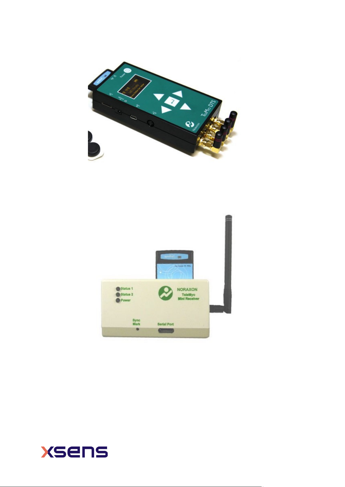
For the Xsens system to receive synchronization commands from Noraxon TeleMyo, the
TeleMyo mini-receive is needed.
5.1 Start and Stop a recording
5.1.1 Hardware connections
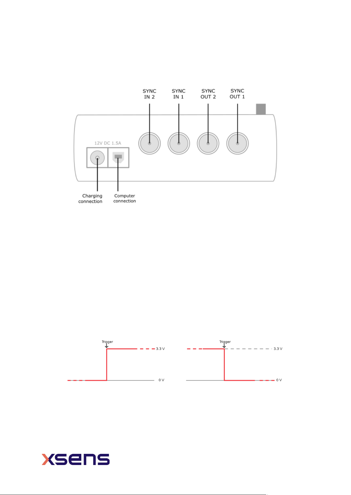
For this set up a BNC connector is required at the Xsens end and a Jack
connector at the
Noraxon end. An easy solution is to use a cable with two BNC coax connectors at
each end, and a BNC to Jack convertor for connecting the BNC to the Noraxon
hardware. USB cables are required to connect each system to the PC.
Note that if the signal received by the Xsens Sync or Awinda Station is 5V, a 5V-
3.3V SMD level translator is advised to prevent damage to the Station.
Set up the hardware of the Noraxon system as follows:
•USB port of TeleMyo mini-receiver to USB of PC.
•Connect jack connector to Sync OUT port of TeleMyo mini-receiver to BNC
connection Sync
•IN 1 of Awinda Station.
•Manual trigger pulse, jack connector to Sync IN port of TeleMyo mini-
receiver.
•Connect the external antenna to the TeleMyo DTS.
•When successfully connected and switched on, the TeleMyo DTS will
display “WiFi ready”.
5.1.2 Noraxon MyoResearch Software
Based on the output settings described for Xsens software the settings for Noraxon
MyoResearch software can remain the same. The difference is that instead of the trigger
pulse coming from the record button in the Xsens software this now comes from the manual
button connected to the TeleMyo mini-receiver. Additionally, the mini-receiver should be
set up as follows:
•Go to the hardware menu;
•Select the TeleMyo mini-receiver from the list of icons;
•Select: settings;
•Select: Configure;
•Ensure that the wireless sync is “External Pulse” and Input Range is ±5V.
oNote that a 5V pulse can cause damage to the Awinda or Sync
Station. For this reason a a 5V-3.3V SMD level translator is advised
to prevent damage to the Station.

10
www.xsens.com
The rest of the software setup is the same as described above. However, instead of
clickingRecord in Xsens software, one should click the hardware trigger supplied by
Noraxon, to generate a manual trigger to both systems.
5.1.3 XSens Software
1. In the Configuration window, in the Sync tab you should select:
Strat recording (in)
Stop Recording (in)
•In 1
•Polarity: Rising Edge
•Skip Factor = 1
•Skip First = 0
•Delay = 0 ms
•Trigger once: uncheck
•In 1
•Polarity: Rising Edge
•Skip Factor = 1
•Skip First = 1
•Delay = 0ms
•Trigger once: uncheck
To initialize recording, click the record button.
The normal red dot icon will change to a pause symbol, indicating that the software is
waiting for an external pulse.
Figure 10 - Motion Capture Configuration window in MVN Analyze. Setting on the sync tab.
Figure 11 - Record button. a) before clicking, b) after clicking, with sync-in activated.
Figure 9 - Configuration of TeleMyo mini-receiver in Noraxon MyoResearch software.

11
www.xsens.com
6Using the Link System
To use the XSens Link system instead of the Awinda system you need to have an Awinda
Station. Then you should activate the Awinda station in the “Motion Capture Configuration
window” by turn on the bottom on the sync station configuration tab. In this tab you can
find all the details described above.
Note: When using the Xsens Link system, which has an output rate of 240Hz, you will still
need to use an Awinda Station to send synchronization signals. As our Awinda station has
a maximum frame rate of 120Hz, you will realise that the maximum frame rate that the
output signal will have is 120Hz. Practically, this entails that every other frame of Xsens
will be synchronize with the frame of the other party system. This still gives an optimal
synchronization between both systems.
If you would like to have both systems with the same sampling frequency you should
downsample the file while export. To do so follow the following steps:
-Go to “File” tab - > “Export”
-Select the format you would like to export the data
-Click “Show options” and select the right “Exporter frame skip (for downsampling)”
value.
Figure 12 - Motion Capture configuration window in MVN Analyze. Indications to
activate the Awinda station as sync station with the Link system.
This manual suits for next models
1
Table of contents
Other Xsens Measuring Instrument manuals