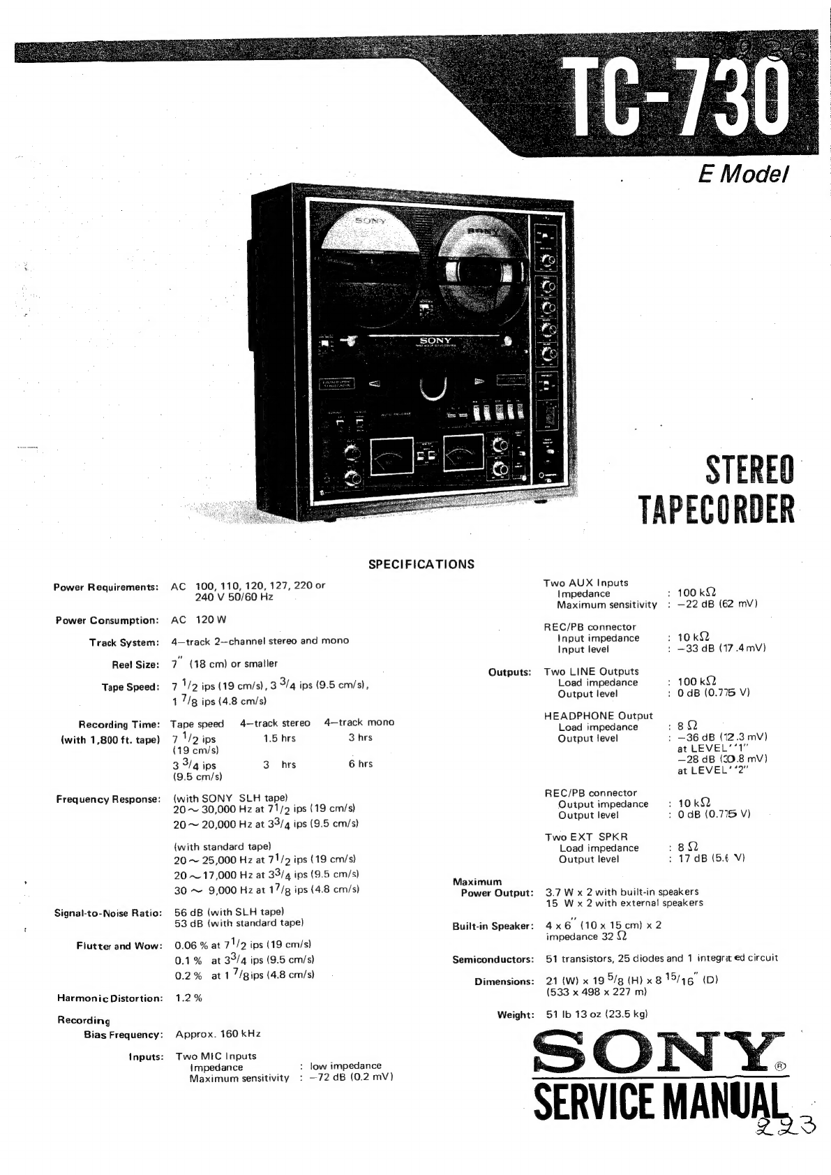
Sony TC-730 User manual

Power
Requirements:
Power
Consumption:
Track
System:
Ree!
Size:
Tape
Speed:
Recording
Time:
(with
1,800
ft.
tape)
Frequency
Response:
Signal-to-Noise
Ratio:
Flutter
and
Wow:
Harmonic
Distortion:
Recording
Bias
Frequency:
Inputs:
SPECIFICATIONS
AC
100, 110, 120,
127,
220
or
240
V
50/60
Hz
AC
120W
4—track
2—channel
stereo
and
mono
7°
(48
cm)
or
smaller
7
\/2
ips
(19
cm/s),
3
3/4
ips
(9.5
cm/s),
1
7/g
ips
(4.8
cm/s)
Tape
speed
4-—track
stereo
4—track
mono
vd
Vo
ips
1.5
hrs
3
hrs
(19
cm/s)
3
3/4
ips
3
hrs
6
hrs
(9.5
cm/s)
(with
SONY
SLH
tape)
20
~
30,000
Hz
at
71/2
ips
(19
cm/s)
20
~
20,000
Hz
at
33/4
ips
(9.5
cm/s)
(with
standard
tape}
20
~
25,000
Hz
at
71/2
ips
(19
cm/s)
20
~
17,000
Hz
at
34/4
ips
(9.5
cm/s)
30
~
9,000
Hz
at
17/g
ips
(4.8
cm/s)
56
dB
(with
SLH
tape)
53
dB
(with
standard
tape)
0.06
%
at
71/2
ips
(19
cm/s)
0.1%
at
39/4
ips
(9.5
cm/s)
0.2%
at1
’/gips
{4.8
cm/s)
1.2%
Approx.
160
kHz
Two
MIC
Inputs
Impedance
Maximum
sensitivity
:
low
impedance
:
—72
dB
(0.2
mV)
Outputs:
Maximum
Power
Output:
Built-in
Speaker:
Semiconductors:
Dimensions:
Weight:
Two
AUX
Inputs
Impedance
Maximum
sensitivity
REC/PB
connector
Input
impedance
Input
level
Two
LINE
Outputs
Load
impedance
Output
level
HEADPHONE
Output
Load
impedance
Output
level
REC/PB
connector
Output
impedance
Output
level
Two
EXT
SPKR
Load
impedance
Output
level
E
Model
STEREO
TAPECORDER
:
100
kQQ
:
—22
dB
(62
mV)
10kQ
:
—33
dB
(17.4mvV)
:
100
kQ2
:
OdB
(0.775
V)
BQ
:
—36
dB
(12.3
mV)
at
LEVEL’*1”
—28
dB
(30.8
mV)
at
LEVEL’
“2”
:
10kQ2
:
OdB
(0.775
V)
:8Q
:
17
dB
(5.6
V)
3.7
W
x
2
with
built-in
speakers
15
Wx
2
with
external
speakers
4x6
(10x
15cm)
x2
impedance
32
(2
51
transistors,
25
diodes
and
1
integrat
€d
circuit
21
(W)
x
19
5/g
(H)
x
8
15/46"
(D)
(533
x
498
x
227
m)
51
Ib
13
oz
(23.5
kg)
‘SERVICE
MANUAL,

Section
N
GENERAL
DESCRIPTION
1-1.
1-2,
1-3.
TABLE
OF
CONTENTS
Title
Specifications
..........
Block
Diagram
.........
Major
Parts
Locations
......
Switch
Location.
........
CIRCUIT
DESCRIPTION
Record
Amp
Circuit
Muting
Circuit
System
Control
3-1.
3-2.
3-3.
3-4,
3-5.
Ac’Servo
Circuit
4-1.
Priciple.
ace.
4.5
See
Bo
SS
4-2.
Servo
Amplifier
Operation.
...
4-3.
Motor
Speed
Deviation
from
Intended
Value
.........
Sequence
of
Switch
Operation.
.
.
DISASSEMBLY
2-1.
Cabinet
Removal...
......
2-2.
Head
Deck
Removal.
......
2-3.
Record
Equalizer
Circuit
Board
Removal.
..........
2-4.
Reverse
Switch
Circuit
Board
Brake
Solenoid
PM602
.....
Reel
Motor
Circuit...
.....
Pinch
Roller
Solenoid
PM601
..
.
Solenoid
Operating
Voltage
....
Removal
ADJUSTMENT
PROCEDURES
3-1.
3-2.
Mechanical
Adjustments.
...
.
Electrical
Adjustments
.....
Section
Title
4.
DIAGRAMS
4-1.
4-1-1.
4-1-2.
4-2.
4-2-1.
4-2-2.
4-2-3.
4-2-4,
4-2-5.
4-2-6.
4-2-7.
4-2-8.
4-2-9.
4-2-10.
4-2-1].
4-2-12.
4-3.
5.
ELECTRICAL
PARTS
LIST
Schematic
Diagram
.......
Audio
Amp
and
Bias
OSC
Circuits
3.05
oe
oe
Ea
System
Control
Circuit
.....
Mounting
Diagram.
.......
Record
Amp
Circuit
Board
Speaker
Selector
Switch
Circuit
Board
..........
Tone
Control
Circuit
Board
...
Power
Amp
Circuit
Board...
.
Relay
Circuit
Board
.......
Power
Supply
Circuit
Board.
.
.
Servo
Control
Circuit
Board.
.
.
Reverse
Switch
Circuit
Board
..
.
.
68
Level
Diagram
6.
EXPLODED
VIEWS
6-1.
6-2.
6-3.
6-4.
6-5.
6-6.
6-7.
6-8.
6-9.
7.
HARDWARE
Cabinet
—
top
view
~—
Head
Deck
—topview—
....
Amplifier
Chassis
Panel
—topview-
..........
Amplifier
Chassis
—
top
view
—
.
Chassis
—
topview—-(1).....
Chassis
—
top
view
—
(2)...
..
Chassis
—
top
view
—(3).....
Chassis
~
bottom
view—-
....
PaCkKin
gw
ao
in2kt
Ge
eos
e
esa
al
Hardware
Nomenclature.
....
When
ordering
replacement
parts,
you
should
use
PART
NUMBER
listed
on
the
Parts
Lists
or
shown
in
the
EXPLODED
VIEW.
The
reference
number
should
not
be
used
for
ordering
purposes.
.
39
.
39
.
41
.
43
.
43
Record
Equalizer
Circuit
Board
. .
46
Playback
Amp
Circuit
Board.
.
.
Bias
OSC
Circuit
Board
.....
SOS/ECHO
Circuit
Board
...
.
.
48
.51
.
54
“55
.
56
.
58
.
60
.
63
.
66
67
.
70
77
279
.
81
.
83
.
85
.
87
.
88
.
89
.
90
941
.
91

SECTION
1
GENERAL
DESCRIPTION
BLOCK
DIAGRAM
1-1.
JINOHdGV3H
{om}
770d
Lon
|
a
AW
[:
|
‘
.
Azu
iN0D
4
Aviad
dd
zogwd
|
2
€
togau
[><]
tat
TS
Fale
1o9Wd
Ee
e
TJ
A001
|S}
sayO"
YOUId
SI
II'>
aad
|
mee
Re
oO
¥
mM
rere
=
39VLIOA
cor
4ayeads
d
urying
AIH
NON
dS
2
euiatiee
(2198)
I
q
:
AlddNS
4IMOd
60L0
YIZIMNEVLS
80L7~
1020
dWVY
Y3MOd
Z0S
“1090
2s0
svia
ANOHdOV
3H
voir
oO
90ED
ONILNW
SO0ED
dWY
YILIN
Hd
®@
INOHdQV3H
~~
ATH
gots
Au
,
FOuNOS
OE
‘E0E0
Hd
dNVY
INIT
~
GMs
4NO
3NIT
coir
OHIH/SOS
ZO
“L010
dWV
JIN
SOt
‘vOt
“E010
dWY
934
NI
XNW

1-2.
MAJOR
PARTS
LOCATIONS
Cabinet
—
Top
View
—
X-34980-81
X-34970-46
reel
panel
knob
ass’‘y,
ass
‘y,
complete
AUTO
REV
|
|
X-34970-47
cover
assy,
h@ad
-
rr
X-34970-46
knob
assy,
1-5
14-867
switch,
slide;
TAPE
SELECT
(S108)---~-----—-—
1-514-768
switch,
lever;
HEADPHONE
LEVEL
(S109)-------
1-507-282
jack,
binaural;
:
HEADPHONE
(J104)
ack
:
Fen
R(J202)
|
at
t
igieaditt
\
X-34970-50
AUX-L
——--—
|
|
|
knob
(A)
ass‘y,
i
|
|
control
AUX-R
-
:
|
i
of
;
i
{
|
M
Si
oe
J
}
1-524-082-11
EME
|
|
|
meter,
VU
R(ME2)
———--—________-—
{
j
L
(S105)
R
($205)
1-5
14-836
switch,
MONITOR
Cabinet
—
Side
Views
—
EXT
SPKR
171-536-309
push
terminal,
—
4P
(35701)
1-507-142
Jack,
AUX
IN
(J101,
201)
171-509-359
connectors,
REC/PB
3-497-237
terminal,
GND
171-507-142
tack,
LINE
OUT
(S703,
203)
1-514-868
switch,
lever
ECHO/SSOS
(S110)
‘
VOLUME
__
1-§14-869
switch,
lever;
~
MIC-R
X-34980-01
“cabinet
assy
SOS/ECHO
X-34980-02
TREBLE
knob
(B)
ass'y,
contro!
BASS
knob
(A)
ass’y,
control
-
ees
X-34970-50
SPKR
SELECT
(S702)
X-34580-22
knob
ass’y,
selector
1-514-866
switch,
seesaw;
POWER
AMP
(S701)
1-507-282
jack,
binaural;
HEADPHONE
(J702)
AUX-R
\
X-34970-50
knob
(A)
ass’y,
control
~R
x.34970-45
button
ass’y,
REC
_.
1-533-048
holder,
fuse
1-509-427
socket,
power
voltage
selector
(VS6071)
UNSWITCHED-
-300W--
171-509-341
—-
connector,
AC
i
OUTLET
(CNJG071}
1-534-487
cord,
power

Chassis
—
Top
View
—
X-34970-26
reel
table
ass’y
1-454-075
;
solenoid
plunger;
—_—__7al
pinch
roller
(PM601)
j
8-829-142-20
———
head,
playback
(PP102-4202)
8-828-629-20
head,
record/erase
{ERP102-2902)
3-497-207
pinch
roller
1-222-497
resistor,
variable;
AUX
30
kQ.(D)
(R136)
1-222-498
1-524-082-11
resistor,
variable;
meter,
VU
(ME7,
2)
MIC
10
k82(D)
(R135)
Chassis
—
Bottom
View
—
1-441-730
8-833-012-01
transformer,
power
motor,
fan
(T601)
(1S-024A]}
8-836-624-07
motor,
reel
(UC-624K)
X-34980-51
mounted
circuit
board,
tone
control
X-34980-52
mounted
circuit
——-——
board,
power
amp
X-34980-56
mounted
circuit
board,
speaker
selector
switch
1-454-074
solenoid,
plunger;
direction
(PM603)
X-34970-61
X-34970-64
mounted
circuit
mounted
circuit
board,
record
amp
_
board,
bias
osc
8-828-629-20
head,
record/erase
(ERP
102-2902)
171-221-910
S<—
resistor,
variable
50
kQ.(C)
(ECHO/SOS)
171-221-917
"
ggrl-
resistor,
va-iable
50
kKQ.
(A)
TREBLE
p
1-221-917
42
resisotr,
variable
50
k82.(A}
BASS
1-222-499
resistor,
variable
500
k82
BALANCE
gael
1-221-917
resistor,
variable
50
k82.
(A)
VOLUME
Y-20410-12-9
counter,
tape
index
—*1-514-870
switch,
rotary;
MODE
1-222-497
resistor,
variable,
AUX
30
k91{D)
(R236)
1-222-498
resistor,
variable,
MIC
10
k§2(D)
(R235)
1-454-074
solenoid,
plunger;
brake
(PM602)
8-836-624-07
motor,
reel
(UC-624K)
X-34970-66
mounted
circuit
board,
relay
X-34970-68
mounted
circuit
board,
servo
control
X-34980-53
mounted
circuit
board,
power
supply
8-836-214-01
motor,
capstan
(UC-214G)
-
X-34970-62
mounted
circuit
board,
record
equalizer
mounted
circuit
board,
playback
amp

1-3.
SWITCH
LOCATION
S614
(upper
side)
PLAY,
FF-STOP
switch
(4)
S605
(lower
side)
PLAY,
FF-STOP
switch
(2)
S610
(upper
side)
PLAY,
FF-STOP
switch
(3)
S613
i
.__.§602
(lower
side)
te”
PLAY,
FF-STOP
switch
(1)
S604
(upper
side)
S620
—~-
PLAY-FF,
STOP
switch
(1)
.
PLA
Y-FF,
STOP
S612
{lower
side)
switch
(4)
PLAY-FF,
STOP
switch
(2)
=
S609
S618
AUTO
SHUT-OFF
switch
AUTO
OFF
swit
OFF
switch
S616
S607
PLAY
switch
(3)
FF
switch—
PLAY
switch
(2)
-
S608
PLAY
switch
(1)
~~
S606
STOP
switch
woes
SHIT
FF
switch
(2)
S619
(upper
side)
FWD-REV
switch
(2)
S607
(lower
side)
FWD-REV
switch
(1)
;
3
E
|
!
i

CIRCUIT
DESCRIPTION
The
following
describes
operation
of
main
circuit:
1.
RECORD
AMP
CIRCUIT
First
stage
of
the
record
amplifier
comprises
NPN
and
PNP
type
transistors
connected
in
parallel.
This
circuit
improves
linearity
characteristics
of
record
amplifier
for
MIC
jack
input
signals.
Approximately
50
dB
linearity
can
be
obtained.,
Therefore,
can
record
signals
with
greater
input
level
(approximately
—10
dB,
0.25
V
to
MIC
jack)
with
low
distortion.
Linearity
for
conventional
circuit
which
has
only
one
transistor
is
approximately
30
dB.
2.
MUTING
CIRCUIT
During
direction
change
of
tape
transport
(about
three
seconds),
from
the
time
when
tape
stops
moving
until
tape
motion
reverses
and
recoveres
to
normal
tape
speed,
B
+
voltage
of
bias
oscillator
is
cut
off
in
record
mode
and
the
muting
circuits
(Q306
and
Q406)
of
playback
amplifier
are
activated
in
playback
mode.
When
turning
POWER
switch
ON,
the
multivibrator
(Q504
and
Q505)
is
kept
stable
as
follows:
POWER
switch
is
turned
ON.
Initial
current
through
C505
turns
0505
ON.
Decreased
collector
voltage
of
0505
turns
Q504
OFF.
After
C505
has
been
charged,
Q505
base
bias
is
applied
through
R507.
0505
is
kept
ON.
Decreased
collector
voltage
Decreased
collector
voltage
of
Q505
keeps
0306
and
of
0505
keeps
O506
OFF.
Q406
OFF.
Playback
amplifier
normal-
O503
is
kept
ON
and
sup-
ly
works.
plies
B+
voltage
to
bias
oscillator.
When
changing
the
unit
from
FWD
mode
to
REV
mode
or
vice
versa,
this
circuit
acts
as
follows:
FWD—
REV
REV
—
FWD
Negative
trigger
pulse
Positive
trigger
pulse
through
D614
turns
through
D613
turns
Q505
OFF.
Q504
ON.
Increased
collector
voltage
of
0505
turns.0504
ON.
Collector
voltage
of
Q504
decreases.
Current
flows
through
R506
and
through
R507
and
C505.
C505
discharges
for
about
three
seconds.
During
the
discharge,
Q505
is
turned
OFF
by
decreased
base
bias.
Increased
collector
voltage
of
O505
turns
Q506
ON.
Increased
collector
voltage
of
Q505
turns
Q306
and
Q406
ON.
Q306
and
Q406 Q503
turns
OFF
ground
audio
and
cut
off
B+
signals.
voltage
to
bias
oscillator.
After
the
discharge,
current
stops
flowing
through
R507
and
C505.
Q505
is
turned
ON
by
increased
base
bias.
0504
is
turned
OFF.
:
:
j
E
é
:

Bt
From
power
supply
circuit
Q503
Q306
(0406)!
o
UPLAY
S614
Muting
circu
Collector
voltage
of
Q505
rises
for
sTopo
PLAY
FF
a
=p
S103-2
about
three
seconds
when
the
meade
switch
is
changed,
and
then
306
(Q406)
turns
ON.
D604
Fig.
7.
3.
SYSTEM
CONTROL
3-1.
Brake
solenoid
PM602
When
FWD
button
is
pushed,
S608
turns
ON.
Then
high
voltage
(about
170
volts
dc)
rectified
by
D604
is
applied
to
PM602
through
S605.
PM602
is
energized.
3-2.
Reel
motor
circuit
The
motor
current
flows
as
follows:
46
V
or
80
V
terminals
of
power
transformer
——»
$612
———»
R609
————-contacts
of
relay
RY602-———
reel
motors
M2,
M3
—»
$610
————~-
0
V
terminal
of
power
transformer
3-3.
Pinch
roller
solenoid
PM601
When
S602
is
turned
ON
by
solenoid
PM602,
high
voltage
(about
170
volts
dc)
rectified
by
D604
is
applied
to
PM601
through
S604.
PM601
is
energized.
Bt
To
bias
osc
circuit
ral”
V
(in
FWD
mode)
OV
lin
REV
mode)
RY601
Muting
circuit
3-4.
Solenoid
operating
voltage
Solenoids
(for
brake,
pinch
roller,
and
tape
direction)
are
energized
by
high
voltage
(about
170
volts
dc)
and
kept
energized
by
low
voltage
(about
30
volts
dc).
3-5.
S612
This
switch
supplies
a
high
reel-motor-driving
voltage
(80
volts
ac)
to
make
strong
tape
tension
in
a
starting
moment,
because
of
tape
slack
elimination.
When
pressing
FWD
or
REV
button,
$612
supplies
80
volts
ac
for
about
one
second
unitl
pinch
roller
solenoid
PM601
actuates
S612.
After
solenoid
PM601
has
actuated
S612,
S613
supplies
46
volts
ac
for
normal
tape
tension.

FF,
STOP
REW
right
reel
motor
self-locking
{Turns
ON
when
contacts
of
\FWD
button
is
pushed,
RY602
S607
Turns
ON
when
FF
or
REW
button
is
pushed
RY602
FF
relay
Fig.
2.
Reel
motor
circuit
4.
AC
SERVO
CIRCUIT
The
Model
TC-730
employs
ac
servo
amplifier
circuit
and
keeps
tape
speed
constant.
4-1.
Principle
See
block
diagram
in
Fig.
3.
Motor
speed
determined
by
voltage
Em
can
be
changed
by
voltage
Er.
E
(fixed)
=
Em
+
Er
When
motor
speed
becomes
faster
or
slower
than
intended
speed
according
to
external
disturb-
ances,
the
intended
motor
speed
can
be
obtained
again
by
changing
voltage
Er,
or
by
changing
resistance
R.
The
frequency
generator
FG
in
the
motor
detects
motor
speed
deviation.
Servo
amplifier
changes
resistance
R
according
to
the
deviation.
TC-730
uses
impedance
R
between
collector
and
emitter
of
tran-
sistor
Q901
instead
of
resistance
R
as
shown
in
Fig.
4.
Impedance
R
can
be
changed
by
the
base
voltage.
The
motor
speed
can
be
kept
stable
by
controlling
the
base
voltage
for
the
motor
speed
deviation.
The
bridge
type
rectifier
comprising
four
diodes
makes
current
flow
through
transistor
Q901
in
the
direction
shown
by
the
arrow
in
Fig.
4.
Efconstant)
SERVO
AMP
Fig.
3.
Servo
control
system
block
diagram
SERVO
AMP
Fig.
4.
Q9017
instead
of
resistance
R
Outline
of
IC
(CX-032})
Q2
Fig.
5.
Servo
amplifier
outline
Ac
4-2.
Servo
amplifier
operation
Servo
amplifier
which
changes
impedance
R
operates
as
follows:
See
Fig.
5
and
Fig.
6.
1)
2)
3)
4)
Sine
wave
signal
generated
by
frequency
ge-
nerator
FG
is
transfered
to
bases
of
Q1
and
Q?2.
Since
base
bias
voltages
of
Q1
and
Q2
are
set
to
saturation
region,
sine
wave
signal
is
waveshaped
to
square
wave
signal
shown
by
(A)
in
Fig.
6.
Square
wave
signal
from
Q2
is
amplified
by
Q3,
Q4
and
QS.
It
is
transfered
to
differentiating
circuit
comprising
Cl
and
R1
and
is
wave-
shaped
to
pulse
shown
by
(B)
in
Fig.
6.
Then
it
is
transfered
to
base
of
Q6.
De
voltage
Vs
stabilized
by
Q12
is
divided
by
R3
and
R4.
Then
it
is
transfered
to
base
of
Q8
and
keeps
the
emitter
voltage
Ek
of
Q8
(also
that
of
Q7)
constant.
Vs
also
charges
C2
according
to
the
time
constant
decided
by
C2
and
R2.
The
charged
voltage
is
applied
to
collector
of
Q6.
When
pulse
shown
by
(B)
in
Fig.
6
is
transfered
to
base
of
Q6,
Q6
repeats
ON
and
OFF
states.
C2
discharges
while
Q6
makes
current
flow
as
shown
by
the
arrow
(1)
in
Fig.
5.
Thus
sawtooth
wave
signal
shown
by
(C)
in
Fig.
6
is
obtained
at
collector
of
Q6.
—10—
5)
6)
4-3.
1)
The
sawtooth
wave
signal
is
supplied
to
base
of
Q7.
Since
the
emitter
voltage
Ek
is
kept
con-
stant,
Q7
turns
ON
only
when
the
peak
value
of
sawtooth
wave
signal
is
greater
than
Ek.
When
Q7
turns
ON,
the
negative
pulse
shown
by
(D)
in
Fig.
6,
appears
at
collector
of
Q7.
This
pulse
is
amplified
by
Q9,
Q10
and
Q11,
and
its
polarity
is
inverted.
The
positive
pulse
is
transfered
to
the
integrator
comprising
R5
and
C3,
and
is
waveshaped
as
shown
by
(E)
in
Fig.
6.
After
being
amplified
by
Q13
and
Q14,
it
is
transfered
to
base
of
Q901.
And
this
base
voltage
changes
impedance
between
collector
and
emitter
of
Q901
and
controls
motor
speed.
Motor
speed
deviation
from
intended
value
When
motor
speed
becomes
faster
(Fig.
7);
Switching
speed
of
Q6é
becomes
faster
since
frequency
of
frequency
generator
FG
increases.
Collector
voltage
of
Q6
is
grounded
before
it
becomes
greater
than
emitter
voltage
Ek
(con-
stant)
because
of
short
charging
time
for
C2.
The
peak
value
of
the
sawtooth
wave
signal
at
base
of
Q7
is
less
than
Ek.
Thus
Q7
turns
OFF,
and
base
voltage
of
Q901
decreases
since
the
pulse
is
not
supplied
to
base
of
Q9.
When

2)
3)
impedance
R
becomes
greater,
motor
voltage
Em
decreases
and
motor
speed
decreases
to
the
intended.
When
motor
speed
becomes
slower
(Fig.
8)
;
Switching
speed
of
Q6
becomes
slower
since
frequency
of
frequency
generator
FG
decreases.
Collector
voltage
of
Q6
is
grounded
after
it
becomes
greater
than
emitter
voltage
of
Q7
because
of
sufficient
charging
time
for
C2.
The
peak
value
of
the
sawtooth
wave
signal
at
base
of
Q7
is
higher
than
Ek.
Thus
Q7
turns
ON
for
T
seconds,
and
base
voltage
of
Q901
increases
since
the
pulse
is
supplied
to
base
of
Q9,
when
impedance
R
becomes
less,
motor
voltage
Em
increases,
and
motor
speed
increases
to
the
intended
speed.
Thus
by
changing
the
time
T
motor
speed
is
controlled.
.
Time
T
is
determined
by
charging-time
of
C2
(the
inclination
of
the
sawtooth
wave).
In
this
ac
servo
circuit,
the
time
constant
(C2
x
R2)
for
charging
time
is
determined
by
R2
for
the
specified
tape
speed.
Circuit
operation
when
motor
starts
running;
Just
after
the
power
switch
is
turned
ON,
Q6
is
still
turned
OFF
since
signal
is
not
supplied
from
the
frequency
generator
(motor.
is
not
running).
C2
is
charged
rapidly,
and
greater
voltage
than
Ek
is
applied
to
base
of
Q7.
When
base
voltage
of
Q901
increases,
ac
voltage
is
FG
output
signal
approx.
900
Hz
at
19
cm/s
(7
%
ips)
collector
of
Q2
base
of
Q6
collector
of
O6
collector
of
Q7
base
of
Q901
Fig.
6.
|
Waveform
at
each
point
qe:
applied
to
the
motor
and
the
motor
starts
running
rapidly.
In
the
FF
mode,
the
servo
circuit
does
not
work
and
ac
voltage
is
applied
to
the
motor
directly.
Then
motor
rotates
at
full
speed.
FG
output
signal
(short
cycle)
collector
of
Q2
base
of
O6
(short
cycle)
|
base
of
Q7
Ek
LAA
(peak
value
lower
than
Ek}
no
pulse
collector
of
Q7
at
base
of
Q907
(decreases)
Fig.
7.
When
motor
speed
becomes
faster
(long
cycle)
collector
of
Q2
base
of
Q6
(long
cycle)
base
of
Q7
(peak
value
base
of
Q901
(increases)
Fig.
8.
When
motor
speed
becomes
slower
FG
output
signal
higher
than
Ek}
collector
of
Q7
SEQUENCE
OF
SWITCH
OPERATION
Note:
The
number
in
circle
shows
the
sequence
of
switch
operation
when
the
mode
is
changed.
FWD
Button
Is
Pushed
@
S615
turns
ON.
@
S608
turns
ON.
In
the
REV
play
mode,
the
tape
Brake
solenoid
(PM602)
is
energized.
direction
relay
(RY601)
and
solenoid
(PM603)
are
energized
(FWD
play
mode)
@®
$602
turns
ON.
®
S610
turns
ON.
Pinch
roller
solenoid
(PM601)
is
energized,
Reel
motors
start
to
rotate.
@®
$605
is
changed
to
FF,
PLAY
@
S614
turns
ON.
position.
The
voltage
across
B+
voltage
for
bias
osc
circuit
brake
solenoid
(PM602)
de-
is
not
supplied
yet
because
creases.
S613
turns
OFF.
©
S618
turns
ON.
If
the
POWER
MAIN
switch
is
set
to
AUTO
OFF,
the
machine
turns
off
automatically
at
the
end
of
the
tape.
©
S620is
changed
to
PLAY
position.
®
S613
ischanged
to
PLAY
position.
Dummy
resistor
R611
in
B+
circuit
B+
voltage
is
supplied
to
bias
osc
is
cut
off
by
S620.
circuit.
©
S604
is
changed
to
PLAY
position.
@
S612
is
changed
to
PLAY
position.
The
voltage
across
pinch
roller
solenoid
(PM601)
decreases.
(After
one
second
since
S604
is
changed
to
PLAY
position
(6)).
FF
Button
Is
Pushed
®
S611
is
changed
to
FF
position.
@
$607
turns
ON.
FF
relay
(RY602)
is
energized
(FF
position).
The
motor
circuit
is
changed
to
supply
the
rated
voltage
to
each
reel
motor.
@®
Self-locking
contact
(1)
of
FF
relay
@
Contact
(2)
of
RY602
is
closed.
@
Contacts
(3)
and
(4)
of
RY602
are
RY602)
i :
(
02)
is
closed
Brake
solenoid
(PM602)
is
energized.
closed.
Pinch
roller
solenoid
(PM601)
is
de-energized.
AC
rated
voltage
is
supplied
to
reel
motors.
@®
S602
turns
ON.
@
$610
turns
ON.
Reel
motors
start
to
rotate.
These
actions
@
are
not
@®
S605
is
changed
to
FF
position.
@®
S614
turns
ON.
related
to
FF
operation.
The
voltage
across
brake
solenoid
(PM602)
decreases.
—12—

SECTION
2
DISASSEMBLY
2-1.
CABINET
REMOVAL
head
cover
®OB3Ix8
head
cover
pin
ye
RK
3x
10
(black)
ornamental
washer
W3
©
ree!
panel
washer
&
control
knob
(8)
L
selector
knob
control
knob
(A}
3
ornamental
washer
@
RK3x
ey
reel
pane!
washer
©)
reel
panel
unit
@
RK
4x
35
|
washer
GS
cabinet
rubber washer
&&
monn
ab
inet
|
-
|
cabinet
washer
e
P4x6
24372

2-2.
HEAD
DECK
REMOVAL
2-4.
REVERSE
SWITCH
CIRCUIT
BOARD
REMOVAL
1.
Remove
the
FWD
and
REV
lamps.
reverse
switch
@
@®
PSW3x6
circuit
board
2.
Remove
the
five
screws
shown
in
Fig.
2-2.
Lift
off
the
head
deck.
Go
PS
4x8
owas
lamp
lamp
(for
REV)
{for
FWD}
Fig.
2-4.
|
Reverse
switch
circuit
board
removal
Note:
Pay
attention
not
to
cut
the
head
lead
wires.
Fig.
2-2.
Head
deck
removal
2-3.
RECORD
EQUALIZER
CIRCUIT
BOARD
REMOVAL
®
PSW3x
8
CAUTION:
1)
Install
the
playback
and
bias
osc.
circuit
boards,
after
the
levers
are
perfectly
hooked
to
the
holes
of
the
slider
of
the
slide
switches.
2
The
lead
wire
of
microswitch
has
a
connector,
which
is
connected
to
the
other
lead
wire
with
a
special
jig.
\f
the
lead
wire
is
cut
or
the
connector
is
damaged,
solder
the
lead
directly
to
the
microswitch
terminal
with
an
insulating
tape
wound
around
the
terminal.
3
Never
put
the
unit
upside
down
on
the
hard
plate
Fig.
2-3.
Record
equalizer
circuit
board
removal
with
the
head’
Cover
removed.
-he:
pin
COP
sie
“tape
shifter,
the
shut-off
arm
pin,
the
tension
arm
and
Note:
After
reattaching,
make
the
equalizer
switch
(S107)
others
will
be
bent
because
of
the
weight
of
the
position
adjustment
(See
page
15).
unit.
If
it
is
necessary
to
put
the
unit
upside
down,
put
it
ona
soft
cloth
with
the
head
cover
attached.
—14—

SECTION
3
ADJUSTMENT
PROCEDURES
3-1.
MECHANICAL
ADJUSTMENTS
(3-1-18)
REC
lock
pull
rod
adjustment
(3-1-4)
PLAY,
FF-STOP
(3-1-12)
brake
torque
switch
(S605,
614)
adjustment
position
adjustment
(3-1-5)
PLAY,
FF-STOP
switch
‘
(3-1-3)
brake
solenoid
(PM602,
(S602,
610)
position
adjustment
position
adjustment
(3-1-20)
PLAY-FF,
STOP
switch
‘S613,
620)
adjust.
f
Led
Relren’
(3-1-8)
reel
table
height
adjustment
(3-1-8)
reel
table
height
adjustment
(3-1-7)
lock
arm
bracket
position
(3-1-6)
pinch
roller
adjustment
solenoid
(PM601}
position
adjustment
(3-1-1)
PLAY-FF,
STOP
switch
(S604,
612)
position
adjustment
(3-1-2)
MUTO
SHUT-OFF
switch
(S609)
position
adjustment
(3-1-22)
AUTO
OFF
switch
(S618)
position
adjustment
tape
contact
check
of
scrape
filter
roller
(3-1-9)
servo
control
circuit
board
position
adjustment
(3-1-21)
PLAY
switch
(S675,
616)
(3-1-14)
pinch
roller
pressure
position
adjustment
adjustment
(3-1-19)
equalizer
switch
(3-1-13)
direction
change
capstan
bearing
position
(S107)
position
stopper
adjustment
adjustment
(See
page
21)
adjustment
Fig.
3-1.
Adjusting
parts
locations
(1}
3-1-11)
FF
and
REW
back
tension
adjustmert
(3-1-10)
FWD
and
REV
bick
tension
adjustment
(3-1-16)
FWD
REV
switch
(S601,
619)
position
adjustment
(3-1-15)
direction
switch
jo
int
rod
stroke
adjustrent
(3-1-18}
REC
lock
pull
(3-1-17)
record
button
rod
adjustment
block
adjustment
Fig.
3-2.
Adjusting
parts
locations
(2)
~15—
|
|
|
|
q
|
|
|

Note:
When
the
unit
is
set
to
FWD,
REV,
FF,
REW,
or
REC
mode
with
the
no
tape
threaded,
hold
the
both
actuator
pins
so
that
the
AUTO
SHUT-OFF
switch
is
activated
(a
rubber
band
or
a
piece
of
masking
tape
will
hold
the
actuator
as
though
tape
were
threaded
on
the
unit).
:
3-1-1.
PLAY-FF,
STOP
Switch
(S604,
612)
Position
Adjustment
Make
the
following
adjustments
by
loosening
the
two
microswitch
holding
screws.
See
Fig.
3-3.
After
that,
apply
Jock
paint
to
them.
1.
STOP
mode
(Lock
arm
B
is
locked)
Make
sure
that
the
actuator
of
microswitch
is
perfectly
pushed
with
the
plate
spring
as
shown
in
Fig.
3-3.
De
FWD
or
REV
mode
(Lock
arm
B
is
released.)
The
actuator
of
microswitch
should
not
be
pushed
by
the
plate
spring
at
all.
3.
STOP
to
FWD
(or
REV)
mode
S604
should
be
released
approximately
one
second
after
S612
is
released.
er
—
S604
PLAY-FF,
STOP
switch
(ower
—
S612
lock
arm
(B)
to
be
parallel”
release
Fig.
3-3.
PLAY-FF,
STOP
switch
(S604,
612)
position
adjustment
3-1-2,
AUTO
SHUT-OFF
Switch
(S609,
618)
Position
Adjustment
lL.
Make
sure
that
the
bent
portion
of
the
actuator
pin
is
positioned
vertically
against
the
chassis.
If
necessary,
adjust
by
bending
the
base
of
the
pin.
Dis
Loosen
the
two
microswitch
holding
screws.
Adjust
the
position
of
the
microswitch
so
that
the
switch
is
turned
ON
by
the
actuator
pin
at
the
position
shown
in
Fig.
3-4.
:
3.
Apply
lock
paint
to
the
screws.
ZAG
Note:
Adjust
for
both
AUTO
SHUT-OFF
the
same
way.
switch
in
AUTO
ioe
switch
(S609)
actuator
\
0~0.5mm
,
Tighten
screw
here.
(0~1/64")
/
_-”
Adjust
by
bending
here.
actuator
pin
Fig.
3-4.
actuator
pin
AUTO
SHUT-OFF
switch
(S609)
position
adjustment
3-1-3.
Brake
Solenoid
(PM602)
Position
Adjustment
1.
Turn
OFF
the
power.
Unhook
either
end
of
the
spring
and
loosen
the
four
solenoid
holding
screws.
See
Fig,
3-5.
2
Push
the
solenoid
shaft
to
the
full
with
a
hand
in
the
direction
shown
by
the
arrow.
Adjust
the
position
of
the
solenoid
so
that
the
clearance
between
the
timing
lever
and
the
lock
lever
is
0
to
0.5
mm
(1/64").
Make
this
adjustment
perfectly
otherwise
an
unusual
noise
is
produced
because
of
the
vibration
of
the
brake
lever.
3.
Hook
the
spring
again
and
turn
ON
the
power.
Change
the
mode
from
FWD
(REV)
to
STOP
and
vice
versa
several
times.
Make
sure
that
the
unusual
noise
is
not
produced.
Adjust
the
position
of
the
solenoid,
if
necessary.
4.
Apply
lock
paint
to
the
screws.
brake
solenoid
screw
a
(PM602)
ToT
XS
4
Push
solenoid
shaft.
'
©/
\®
_
timing
lever
|
#-
an
brake
lever
!
“=
aes
Sacer
+
O0~0.5mm
,
Adjust
by
(0~1/64
)
positioning.
Unhook
either
end
of
spring.
=*_
stopper
tock
lever
spring
Fig.
3-5.
Brake
solenoid
(PM602}
position
adjustment

3-1-4.
PLAY,FF-STOP
Switch
(S605,
614)
Position
3-1-6.
Pinch
Roller
Soienoid
(PM601)
Position
Adjustment
Adjustment
l.
Place
the
unit
in
the
FF
or
REW
mode,
to
ener-
1.
Loosen
the
three
solenoid
holding
screws
gize
the
brake
solenoid.
Check
to
see
that
the
shown
in
Fig.
3-8.
actuator
of
microswitch
is
perfectly
pushed
with
the
plate
spring
and
also
that
the
no
clearance
between
the
microswitch
and
the
plate
spring
is
obtained
as
shown
in
Fig.
3-6.
If
necessary,
adjust
the
position
of
the
micro-
switch
by
loosening
the
two
switch
holding
2
Place
the
unit
in
the
FWD
or
REV
mode
to
energize
the
solenoid.
Adjust
the
position
of
the
solenoid
so
that
the
clearance
between
the
pinch
roller
pressure
adjusting
plate
and
the
plunger
solenoid
drive
arm
is
0.5
mm(1/64')
to
1
mm
(3/64°).
Tighten
the
screws.
The
Burret
solenoid
shaft
should
be
attracted
straight
on
2;
Apply
lock
paint
to
the
screws.
the
line
and
in
parallel
with
the
solenoid.
3.
Apply
lock
paint
to
the
screws.
Note:
Be
carefui
not
to
turn
OFF
the
microswitch
with
screw
the
solenoid
energized,
as
the
thermistor
(Pth601)
on
AN
the
relay
circuit
board
will
be
damaged
because
of
an
unusual
current.
PLAY,
FF—STOP
switch
ees
-—
S605
-0.5~!mm
(1/64
~
3/64
}
upper
~
S614
‘
\
:
pinch
roller
solenoid
7
\
(PM601)
/
\
7
actuator
plunger
solenoid
_
pinch
roller
pressure
drive
arm
adjusting
plate
~~
NO
clearance
pisteapring
Fig.
3-8.
Pinch
roller
solenoid
(PM601)
position
adjustment
Fig.
3-6.
PLAY,
FF-STOP
switch
(S605,
614)
position
adjustment
3-1-7.
Lock
Arm
Bracket
Position
Adjustment
3-1-5.
PLAY,FF-STOP
Switch
(S602,
610)
Position
1.
Make
sure
that
the
clearance
between
the
lock
‘
Adjustment
arm
(A)
and
the
lock
arm
(B)
is
0.5
~1
mm
(1/64
~
3/64)
in
the
FWD
(or
REV)
mode.
1.
Place
the
unit
in
the
FF
or
REW
mode,
to
In
the
STOP
mode
the
clearance
between
the
energize
the
brake
solenoid.
Check
to
see
that
lock
arm
(A)
and
the
lock
arm
(B)
should
be
the
actuator
of
microswitch
is
perfectly
pushed
approximately
|
mm
(3/64’).
See
Fig.
3-9.
i
the
timi
1
é
i
ig.
3-7.
Wee
ene
ever
os
Sue
wee
nie
2.
Loosen
the
two
lock
arm
bracket
holding
screws,
If
necessary,
adjust
the
position
of
the
micro-
switch
by
loosening
the
two
switch
holding
screws.
:
3.
Adjust
the
position
of
the
lock
arm
bracket.
Tighten
the
screws.
if
necessary.
See
Fig.
3-9.
2.
Apply
lock
paint
to
the
screws.
4.
Apply
lock
paint
to
the
screws.
actuator
timing
lever
Es
Noe
\
screw
PLAY,
FF—STOP
switch
upper
—
S610
lower
—
S602
Fig.
3-7.
PLAY,
FF-STOP
switch
(S602,
610)
position
adjustment
=47'=

screw
3.
Make
sure
that
the
tape
speed
changes
definite-
lock
arm
(A)
os
_lock
arm
bracket
ly,
when
the
TAPE
SPEED
switch
is
slowly
7
<
changed
to
the
4.8
cm/s,
9.5
cm/s
and
19
cm/s
positions.
Readjust
the
position
of
the
servo
control
circuit
board,
if
necessary.
4.
Apply
lock
paint
to
the
screws.
lock
arm
(B)
ae
pale
3,
ye
i
/\
05x
1mm
/
\
\
(1164~
3/64")
1mm
\
_,
Serva
control
(3/64")
-
"|
circuit
board
\
,
(under
chassis)
bee:
x
STOP
mode
FWD
mode
Fig.
3-9.
Lock
arm
bracket
position
adjustment
s
:
‘
:
TAPE
SPEED
_
>
screw
knob
3-1-8.
Reel
Table
Height
Adjustment
1.
Use
a
7
inch
reel.
2:
Thread
the
tape
along
the
tape
path.
Place
the
unit
in
the
FWD
mode.
If
the
tape
touches
either
flange
of
the
reel,
adjust
the
reel
table
height
by
loosening
the
two
set
screws
with
an
allen
wrench.
Here
the
both
upper
and
lower
Fig.
3-11.
Servo
control
circuit
board
position
adjustment
3-1-10.
FWD
and
REV
Back
Tension
clearances
between
the
tape
and
the
reel
flange
Adjustment
should
be
the
same.
Note:
3.
Tighten
the
set
screws.
Instructions
in
[
Jare
applied
to
the
REV
back
tension
torque
adjustment.
7”
reel
1.
Place
a
7”
reel
with
string
wound
several
turns
/
Aik
counterclockwise
[clockwise]
onto
the
FWD
ve
LIL
[REV]
supply
reel
table.
Tie
the
string
to
the
7
I
—
EF
H
spring
scale.
o
eh
ae
same
cleeranes
2
Measure
the
back
tensions
by
pulling
the
0
to
reel
table
400
g
(14
oz)
spring
scale
at
approximately
9.5
cm/s
(3-3/4
ips)
speed
in
FWD
[REV]
“set
screw
mode.
See
Fig.
3-12.
It
should
be
200
to
240
g-cm
(2.78
to
3.32
02.
:
:
‘
inch).
‘
Fig.
3-10.
Reel
table
height
adjustment
3.
Adjust
the
slider
of
R609
by
loosening
the
3-1-9.
Servo
Contro!
Circuit
Board
Position
screws,
if
necessary.
Adjustment
1.
Loosen
the
two
servo
control
circuit
board
pull
a
scale.
holding
screws
shown
in
Fig.
3-11.
Set
the
tape
reel
speed
switch
to
the
9.5
cm/s
(3-3/4
ips)
position
;
(center).
“Oto
400g.
cm
(5.5
oz.
inch)
2's
Thread
the
tape
along
the
tape
path.
Place
the
Bog
scale
unit
in
the
FWD
mode.
Adjust
the
position
of
onesie
the
servo
control
circuit
board
together
with
the
heat
sink
so
that
the
TAPE
SPEED
is
9.5
cm/s.
Tighten
the
screws.
Fig.
3-12.
FWD
and
REV
back
tension
torque
adjustment
—18—

ene
Weak
2
weak
:
ewe
REV
back
tension
adj.
FF
and
REW
|:
back
tension
~
adj.
-Set
this
slider
“FWD
back
tension
adj.
Fig.
3-13.
Back
tension
torque
adjusting
parts
location
3-1-11.
FF
and
Rewind
Back
Tension
Adjustment
Note:
Instructions
in
[ ]
are
applied
to
the
REW
back
tension
adjustment.
1,
Place
a
7”
reel
with
string
wound
several
turns
counterclockwise
[clockwise]
on
the
hub
onto
the
FF
[REW]
supply
reel
table.
Tie
the
string
to
the
spring
scale.
2.
Measure
the
back
tension
by
pulling
the
0
to
400
g
(14
oz)
spring
scale
at
approximately
9.5
cm/s
(3-3/4
ips)
speed
in
FF
[REW]
mode.
See
Fig.
3-12.
It
should
be
60
to
80
g.cm
(0.83
to
1.1
oz
inch).
3.
Adjust
the
slider
of
R608
by
loosening
the
screw,
if
necessary.
3-1-12.
Brake
Torque
Adjustment
This
adjustment
should
be
performed
for
both
supply
and
take-up
sides.
Note:
Instructions
in
[
|
are
applied
to
the
take-up
brake
torque
adjustment.
1.
Place
the
unit
in
the
STOP
mode.
i)
Place
a
7”
reel
with
string
wound
several
turns
counterclockwise
[clockwise]
on
the
hub
onto
to
center
position.
the
reel
table.
Tie
the
string
to
a
spring
scale.
3.
Pull
the
scale
in
the
direction
shown
by
the
red
arrow,
making
sure
that
the
string
does
not
touch
either
flange
of
the
reel.
The
reel
table
will
rotate
counterclockwise
[clock
wise].
Take
a
reading
only
when
the
reel
table
is
in
steady
motion.
4.
The
scale
reading
should
be
900
g.cm
(12.5
oz.
inch)
to
1,200
g-cm
(16.7
oz.inch).
5.
Rewind
the
string
by
turning
the
reel
clockwise
[counterclockwise].
6.
Turn
string
several
times
clockwise
[counter-
clockwise]
on
the
hub
onto
the
reel
table.
Ts
Pull
the
scale
in
the
direction
shown
by
the
black
arrow,
making
sure
that
the
string
does
not
touch
either
flange
of
the
reel,
The
reel
table
will
rotate
clockwise
[counter-
clockwise].
Take
a
reading
only
when
the
reel
table
is
in
steady
motion.
8.
The
scale
reading
should
be
300
g.cm
(4.
17
oz.
inch)
to
400
g.cm
(5.55
oz.inch)
9.
If
the
satisfied
results
are
not
obtained,
adjust
by
changing
the
hooking
position
of
spring.
Specification:
Brake
Torque
of
Supply
Reel
in
clockwise
turning.....
300—400
g.cm
(4.17—5.55
oz-inch)
in
counterclockwise
turning
......
--
900—1200g.cm
(12.5—16.7
oz.-inch)
Brake
Torque
of
Take-up
Reel
in
clockwise
turning
...--
900-—1200g.cm
(12.5-16.7
oZ-inch)
in
counterclockwise
turning
.....
---.
300-40
g.cm
(4.17—5.55
oz-inch)
fate
sprin.
brake
lever.
ne
ra
Owe.
brake
lever
-Y
:
900
~
1200
9.
cm
fee
900
~
1200
g.
cm
(12.5~
16.7
oz.
inch}
=)
(12.5
~
16.7
oz.
inch)
stopper
300~
400
g.
cm
ees
tre
cm—
i
(4.17~
5.55
oz.
inch}
4.17
~
5.55
oz.
inc
Presta
n>
we.
a
“
weak.
{
7
s
fs
hin
4
reel
table
spring
f°
*?
ener
strong
rake
adjusting
arm
Fig.
3-14.
Brake
torque
adjustment
—~19~—

3-1-13.
Direction
Change
Stopper
Position
Adjustment
1.
Loosen
the
stopper
holding
screw.
2.
Place
the
unit
in
the
FWD
(or
REV)
mode.
Adjust
the
position
of
the
direction
change
stopper
so
that
the
clearance
between
the
stopper
and
the
tape
direction
change
lever
is
4
mm
(5/32").
3.
Change
the
mode
from
FWD
to
REV
and
vice
versa
several
times.
Make
sure
that
the
position
of
the
pinch
roller
changes
when
the
mode
is
changed.
4.
Apply
lock
paint
to
the
screws.
pinch
roller
REV
mode
FWD
mode
_
direction
change
lever
io
screw
screw
a
direction"
change
stopper
(L)
“~.
direction
change
stopper
(R)
4mm
(5/32")
in
FWD
mode
4mm
(5/32")
in
REV
mode
Fig.
3-15.
Direction
change
stopper
position
adjustment
3-1-14.
Pinch
Roller
Pressure
Adjustment
1.
Make
a
loop
in
a
piece
of
string
and
attach
the
0
to
1,600
g
(3
1b
8
02)
spring
scale
around
the
base
of
the
pinch
roller
shaft.
See
Fig.
3-16.
Pull
the
scale.
The
pulling
direction
should
be
aligned
with
the
pinch
roller
shaft
and
the
capstan.
Check
the
reading
when
the
pinch
rolier
just
stops
rotating.
It
should
be
1,200
to
1,400
g
(42:
to
49
oz
).
If
necessary,
change
the
hooking
position
of
the
spring.
Adjust
by
changing
the
hooking
position.
strong
a
weak
—~20—
REV
mode
FWD
mode
pinch
‘roller
spring
scale.”
Fig.
3-16.
Pinch
roller
pressure
adjustment
3-1-15.
Direction
Switch
Joint
Rod
Stroke
Adjustment
1.
Place
the
unit
in
the
STOP
mode.
Push
the
tip
of
the
direction
switch
lever
slowly
in
the
direction
shown
by
the
arrow
in
Fig.
3-17
as
far
as
the
slide
switches
on
the
playback
and
the
bias
osc.
circuit
boards
are
changed.
(Do
not
move
the
position
of
switch).
2.
Push
the
REV
button.
Make
sure
that
the
tip
of
the
lever
is
pushed
moreover
by
0.5~1
mm
(1/64
~3/64")
in
the
direction
shown
by
the
arrow
by
the
solenoid.
3.
Change
the
mode
from
the
FWD
to
REV
and
vice
versa
several
times
and
make
sure
that
the
slide
switches
are
changed
perfectly.
4.
Change
the
position
of
direction
switch
joint
tod
to
the
direction
change
lever
if
necessary.
0.5~1mm
direction
switch
joint
rod
(1/64~
3/64")
=
i
i
|
_—!
iu
}
Change
position
of
sy
joint
rod.
Remove
direction
switch
joint
rod
|
by
bending
here.
i
‘
1
direction
switch
lever
Fig.
3-17.
Direction
switch
joint
rod
stroke
adjustment

3-1-16.
FWD-REV
Switch
(S601,
619)
Position
Adjustment
1,
Loosen
the
two
screws.
2.
Place
the
unit
in
the
REV
mode
to
energize
the
direction
change
solenoid.
3.
Adjust
the
position
of
the
microswitch
so
that
the
actuator
is
perfectly
pushed
with
the
joint
plate.
Tighten
the
screws.
4.
Apply
lock
paint
to
the
screws.
direction
solenoid
actuator
as
0.
FWD-—REV
switch
plunger
screw
upper
—
S619
joint
plate
lower
—
S601
Fig.
3-18.
FWD/REV
switch
(S601,
619)
position
adjustment
3-1-17.
Record
Button
Block
Adjustment
1.
See
Fig.
3-19.
Place
the
unit
in
the
STOP
mode.
Check
to
see
that
the
clearance
between
the
REC
button
block
and
the
record
arm
holder
is
0.5
(1/64")
to
1
mm
(3/64").
If
necessary,
adjust
the
position
of
the
REC
arm
holder
by
loosening
the
screws.
2;
Make
sure
that
the
slide
switches
(S103,
104)
on
the
bias
circuit
board
are
perfectly
switched,
when
the
REC
button
is
locked.
Readjust
the
clearance
between
the
REC
button
block
and
the
REC
arm
holder,
if
necessary.
3.
Apply
lock
paint
to
the
screws.
FT
O5~1mm
_
(1/64
~
3/64
}
(When
the
REC
button
released)
record
arm
holder
REC
switch
(S103,
104)
=a
bias
osc
circuit
board
Fig.
3-19.
Record
button
block
adjustment
3-1-18.
REC
Lock
Pull
Rod
Adjustment
1.
Place
the
unit
in
the
STOP
mode.
Turn
the
split
nut
clockwise
until
the
tip
of
the
REC
lock
pull
rod
is
in
contact
with
the
REC
lock
rod.
Moreover,
turn
the
split
nut
slowly
one
or
two
times
after
the
tip
of
the
pull
rod
is
in
con-
tact
with
the
REC
lock
rod.
Press
the
nut
by
using
a
pliers.
2.
Make
sure
the
followings.
a)
Lock
the
REC
button
in
the
STOP
mode.
The
REC
button
is
released
when
the
FWD
or
REV
button
is
pushed.
b)
Lock
the
REC
button
slowly
in
the
STOP
mode.
The
REC
lamp
lights
before
the
button
is
locked.
.
c)
Lock
one
of
the
two
REC
buttons
in
the
STOP
mode.
The
button
is
released
when
another
is
locked.
3.
Apply
contact
cement
to
the
nut.
split
nut
spring.
.<
REC
lock
pull
rod
|_-
REC
lock
tod
no
clearance
in
STOP
mode
Fig.
3-20.
REC
lock
pull
rod
adjustment
3-1-19.
Equalizer
Switch
(S107)
Position
Adjust
ment
L;
Loosen
the
two
screws
as
shown
in
Fig.3-21.
Set
the
tape
speed
switch
to
the
9.5
cm/s
(center)
position.
2:
Move
the
screws
so
that
the
equalizer
svit
ch
is
set
at
the
9.5
cm/s
(center)
position.
3.
Change
the
tape
speed
switch
to
the
4.8cm/s,
9.5
cm/s
and
19
cm/s
positions
and
vic:
wersa
several
times.
Make
sure
that
the
eqalizer
switch
is
definitely
changed.
4.
Apply
lock
paint
to
the
screws.

equalizer
switch
$107
}
_-5
screw
[_——
i.
ees
;
—_—
VU
meter
(L-CH)
Equalizer
switch
(S107)
position
adjustment
Fig.
3-21.
3-1-20.
PLAY—FF,
STOP
Switch
(S613,
620)
Position
Adjustment
1.
Place
the
unit
in
the
STOP
mode.
See
Fig.
3-22.
Make
sure
that
the
distance
between
the
plunger
joint plate
and
the
leaf
A
of
the
leaf
switch
is
0
to
0.5
mm
(1/64°),
and
also
that
the
leaves
A
and
B
are
in
contact
with
each
other
completely.
If
necessary,
adjust
the
switch
position
by
loosening
the
screws.
2:
Place
the
unit
in
the
FWD
(or
REV)
mode,
to
energize
the
pinch
roller
solenoid.
Make
sure
that
the
leaves
A
and
C
are
perfectly
in
contact
with
each
other.
—
Apply
lock
paint
to
the
screws.
PLAY—-FF,
STOP
switch
joe
S620
S613
6
T
“~>>
«screw
screw
—
al,
plunger
joint
plate
0~0.5mm
O~
1/64
O0~0.5mm
:
:
(O~1/64
}
Fig.
3-22.
PLAY-FF,
STOP
switch
(S613,
620)
position
adjustment
3-1-21.
PLAY
Switch
(S615,
616)
Position
Adjustment
(No
adjustment
is
required
for
the
set
having
Serial
No.
10,551
and
later.)
1.
Make
sure
that
S615
(S616)
is
turned
ON
when
the
FWD
(or
REV)
button
is
pushed
and
also
that
it
is
turned
OFF
when
the
button
is
released.
If
necessary,
adjust
the
position
of
PLAY
switch
S615
(or
S616)
by
loosening
the
—~22—
screw
A
(or
screw
B)
in
Fig.
3-23.
Make
sure
that
the
switch
is
not
turned
ON
by
the
play
of
the
FWD
button.
2.
Apply
lock
paint
to
the
screws
A
and
B.
FWD
or
REV
button
o
a
4
PLAY
PLAY
switch,
“
$616
switch
S608
;
“fe
screw
B
(for
S616)
screw
A
(for
S615)
Fig.
3-23.
PLAY
switch
(S615,
616)
position
adjustment
AUTO
OFF
Switch
(S618)
Position
Adiustment
3-1-22
1.
Place
the
unit
in
the
FWD
or
REV
mode
to
energize
the
pinch
roller
solenoid
(PM601).
2;
Loosen
the
two
screws.
3.
Adjust
the
position
of
PLAY
switch
so
that
the
distance
between
the
switch
and
the
plate
spring
is
0
~
0.5
mm
(1/64
).
AUTO
OFF
O~05mm
(0—~
1/64")
~«—
plate
spring
pinch
roller
solenoid
Fig.
3-24.
AUTO
OFF
switch
(S618)
position
adjustment
3-1-23.
Adjustments
after
Head
Replacement
For
FWD
Direction
When
replacement
of
more
than
two
heads
is
‘
required,
leave
one
of
them
unremoved
for
the
refer-
ence
of
adjustments.
Do
not
remove
all
the
heads
at
the
same
time.
A)
Playback
Head
Replacement
1.
Replace
the
playback
head
by
removing
the
angle
adjusting
screws.
See
Fig.
3-27.
Table of contents
Other Sony Measuring Instrument manuals

Sony
Sony MAV-555A User manual

Sony
Sony RDR-HXD790 Use and care manual

Sony
Sony Handycam DCR-TRV6 User manual

Sony
Sony ICD-LX30 User manual

Sony
Sony Handycam HDR-HC9 User manual

Sony
Sony DT12N User manual

Sony
Sony DG10B Series User manual

Sony
Sony TC-366-4 Setup guide

Sony
Sony DCR-PC115 User manual

Sony
Sony PZW-4000 User manual

Sony
Sony DK110NLR5 User manual

Sony
Sony MG40 Series Installation manual

Sony
Sony PWS-100TD1 User manual

Sony
Sony PMA8000C User manual

Sony
Sony TC-580 User manual

Sony
Sony ICD-B200RS User manual

Sony
Sony BVU-800 User manual

Sony
Sony DNW-A100 User manual

Sony
Sony HDR-CX620 User manual

Sony
Sony NEX-FS100C User manual