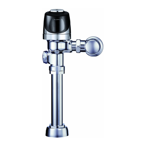
Sloan CX 158 Use and care manual

Repair Parts and Maintenance Guide
CX Manual Flushometer
PARTS LIST
Item
No. Code No. Part No. Description
1See table on next page Piston Assembly
2See table on next page Activation Assembly
2A 3340018 GBL-1018-A Manual Plunger Assembly Repair Kit
30340062 GBL-56 Inlet Adapter 1-1/2" NPT x 1" NPT Closet
0340063 GBL-171 Inlet Adapter 1-1/2" NPT x 3/4" NPT Urinal
4 — — Valve Body*
5 — — Conical Spring**
63340011 GBL-1011-A Safety Collar (Collar for Bonnet)
733400011 GBL-214-A C-Bracket Kit with Screws
8 — — Manual CX Wall Bracket*
8A See table on next page Manual CX Button Only
9See table on next page Manual CX Finished Wall Plate
10 03340012 GBL-1012-A Activation Assembly Tool
11 33400033 GBL-1060-A Manual CX Mud Guard (4 pack)
12 0340085 GBL-66-A Shut Off Sleeve (with O-Ring)
* Not sold separately. ** Included with Piston.
FLUSH CONNECTION PARTS
Item
No. Code No. Part No. Description
13 3323182 V-651 Vacuum Breaker Kit
14 0323011 V-500-A RB Vacuum Breaker Assembly
15 33060011 F-227-A Adjustable Tube 6.5” Replacement Kit, 158, 198
33060012 F-228-A Adjustable Tube 10.5” Replacement Kit, 154
16 0306395 F-211-A CX Poly Washer and Coupling (set of 2)
17 0306392PK F-305 CX Elbow for CX Poly Washer
18 0306091 F-2-A 1-1/2” Coupling with S-21 Gasket
18A 0319079 S-21 Rigid Gasket
19 0306031PK F-1 1-1/2” x 6” Tube
20 0396119PK F-101 CP Tube Outlet 1-1/2” x 10-1/2”
21 0306237PK F-7 Tube Flange 1-1/2” x 2-3/4” with Prongs
Manual Closet Flushometers
CX 158 - 1.6 gpf (Wall Hung)
CX 158 - 1.28 gpf (Wall Hung)
CX 158 - 1.1 gpf (Wall Hung)
CX 154 - 1.6 gpf (Floor Mount)
CX 154 - 1.28 gpf (Floor Mount)
CX 154 - 1.1 gpf (Floor Mount)
Manual Urinal Flushometers
CX 198 - 0.5 gpf
CX 198 - 0.25 gpf
CX 198 - 0.125 gpf
13
14
15
16
For Model 158, Wall Hung
17
18
19 Install with
Flange against spud
For Model 198, Urinals
16
23
For Model 154, Floor Mount Exposed Rear Inlet
16
20
21
22
18A
23A 23B
17
17
22A 22B
3
1
5
2
6
7
8
9
10
11
4
2A
12
8A

Repair Parts and Maintenance Guide
CX Manual Flushometer
ITEM NO. 1 - MANUAL PISTON ASSEMBLY SELECTION GUIDE
Code No. Part No. Description
Piston
Color*
3340053 GBL-1037-A 1.6 gpf/6.0 Lpf Closet Piston Assembly Green
3340054 GBL-1038-A 1.28 gpf/4.8 Lpf Closet Piston Assembly Purple/Black
33400059 GBL-1087-A 1.1 gpf/4.2 Lpf Closet Piston Assembly Grey/Black
3340055 GBL-1039-A 0.5 gpf/1.9 Lpf Urinal Piston Assembly Red
3340056 GBL-1040-A 0.25 gpf/1.0 Lpf Urinal Piston Assembly Burgundy
33400004 — 0.125 gpf/0.48 Lpf Urinal Piston
Assembly†Pink
* Colors may differ. Consult factory to confirm you have the correct assembly.
†0.125 gpf/0.48 Lpf Valve Components (Piston, Main Seat, and Activation Assembly) are NOT
interchangeable with any other flush volume Valves.
ADDITIONAL PARTS
Code No. Part No. Description
—F-304 Poly Washer 1-1/2” (Only available in F-211-A, Item 16)
33400008 GBL-212-A Plunger Screw Kit (screws, wrench, nut, and gauge)
33400012 GBL-215-A Manual Wall Bracket Mounting Screws (Wall Bracket to
Valve, Finished Plate to Wall Bracket)
33400014 GBL-1045-A Manual CX Finished Wall Plate and Button Assembly, SF
‡
33400015 GBL-1046-A Manual CX Finished Wall Plate and Button Assembly, CP
‡
33400016 GBL-1047-A Manual CX Finished Wall Plate and Button Assembly, BN
‡
33400017 GBL-1048-A Manual CX Finished Wall Plate and Button Assembly, PB
‡
33400018 GBL-1049-A Manual CX Finished Wall Plate and Button Assembly, GR
‡
33400039 GBL-1064-A Manual CX Button Only Replacement Kit, SF
33400041 GBL-1065-A Manual CX Button Only Replacement Kit, CP
33400042 GBL-1066-A Manual CX Button Only Replacement Kit, BN
33400043 GBL-1067-A Manual CX Button Only Replacement Kit, PB
33400044 GBL-1068-A Manual CX Button Only Replacement Kit, GR
‡
Includes mounting screws and wrench.
ITEM NO. 2 - ACTIVATION ASSEMBLY SELECTION GUIDE
Code No. Part No. Description Plug Color*
3340048 GBL-1033-A 1.6 gpf/6.0 Lpf Closet Activation Assembly Green
3340049 GBL-1034-A 1.28 gpf/4.8 Lpf Closet Activation Assembly Purple
33400057 GBL-1091-A 1.1 gpf/4.2 Lpf Closet Activation Assembly Grey
3340051 GBL-1035-A 0.5 gpf/1.9 Lpf Urinal Activation Assembly Red
3340052 GBL-1036-A 0.25 gpf/1.0 Lpf Urinal Activation Assembly Burgundy
33400005 — 0.125 gpf/0.48 Lpf Urinal Activation
Assembly
N/A; Nickel
plated brass
* Colors may differ. Consult factory to confirm you have the correct Activation Assembly.
†0.125 gpf/0.48 Lpf Valve Components (Piston, Main Seat, and Activation Assembly) are NOT
interchangeable with any other flush volume Valves.
PLUG
PLUNGER
ASSEMBLY
IMPORTANT NOTE FOR 1.1 GPF
FLUSHOMETERS & REPLACEMENT KITS
Sloan 1.1 gpf/4.2 Lpf ultra-high efficiency flushometers meets all applicable
standards and requirements. However, with low flush volumes it is imperative that
they only be used in conjunction with toilet fixtures and drain line systems designed
to operate with adequate flow rates and volumes in order to effectively eliminate
waste and move it out of the building. It is the responsibility of the user to ensure
both of these conditions are met. Not doing so may void your warranty.
Sloan 1.1 gpf diaphragm and piston kits are designed as a replacement part for
Sloan 1.1 gpf/4.2 Lpf flushometers only. They are not intended to be used as a
means to reduce water consumption in flushometers with higher flush volumes such
as 1.28 gpf/4.8 Lpf or 1.6 gpf/6.0 Lpf or higher. Using this kit in any manner other
than with a Sloan 1.1 gpf flushometer may void your warranty.
ITEM NO. 1 - MANUAL PISTON IDENTIFICATION CHART
Flush Volume 1.6 gpf
Water Closet
1.28 gpf
Water Closet
1.1 gpf
Water Closet
0.5 gpf
Urinal
0.25 gpf
Urinal
0.125 gpf
Urinal
Piston Body Green Purple Grey Red Burgundy Pink
Flow Control Green Black Cage Black Cage Red Burgundy Pink
Part Number GBL-1037-A GBL-1038-A GBL-1087-A GBL-1039-A GBL-1040-A —
Code Number 3340053 3340054 33400059 3340055 3340056 33400004
FLOW
CONTROL
PISTON
BODY
FLUSH CONNECTION PARTS CONTINUED
Item
No. Code No. Part No. Description
22 0306146PK F-5-A 1-1/2” Spud Coupling Assembly CP*
22A 5306058 F-3 Friction Ring 1-1/2"
22B 5322001 VBF-5 Slip Joint Gasket 1-1/2"
23 0306396 —CX Urinal Flush Connection Kit
23A 5306055 F-3 Red Friction Ring 3/4"
23B 5306113 F-5 Gasket 3/4"

Repair Parts and Maintenance Guide
CX Manual Flushometer
TROUBLESHOOTING GUIDE
1. Flushometer Does Not Function (No Water/Flush).
A. Ensure water supply to Valve is turned on.
B. Shut Off Sleeve is in closed position. Turn counter-clockwise to open water flow. Note: there is approximately 1/8-turn (45°) of free spinning as the
Activation Assembly engages the Shut Off Sleeve between opening and closing the Valve.
C. Plunger screw is not adjusted properly. Adjust screw using depth guide.
2. Volume Of Water Is Not Sufficient To Evacuate The Bowl.
A. Plunger screw is not adjusted properly (short button engagement of plunger). Adjust screw using depth guide tool.
B. Insufficient flow pressure. Readjust Activation Assembly by turning counter-clockwise to increase flow pressure.
C. Water supply pressure is inadequate (low). Increase the water supply pressure. Contact the fixture manufacturer for minimum water supply requirements
of the fixture.
D. Wrong model installed; i.e., 0.5 gpf/1.9 Lpf urinal installed on a 1.6 gpf/6.0 Lpf closet fixture. Replace with proper model.
E. Check lip seal for wear. Replace Piston if lip seal is worn or twisted.
3. Too Much Water To Fixture.
A. Excessive flow pressure. Readjust Activation Assembly by turning clockwise to decrease flow pressure.
B. Long Flush. Worn Piston; replace with new proper gpf/Lpf Piston.
C. Wrong model installed; i.e., 1.6 gpf/6.0 Lpf model installed on 0.5 gpf/1.9 Lpf or 0.25 gpf/1.0 Lpf urinal fixture. Replace with proper model per guide.
4. Valve Does Not Shut Off.
A. Plunger screw is not adjusted properly (constant contact on plunger). Adjust screw using depth guide tool.
B. Supply line water pressure has dropped and is not sufficient to close the valve. Close Activation Assembly until pressure is restored.
C. Piston Bypass is clogged, Piston is damaged, or large debris stuck behind Piston. Turn off water at Shut Off Sleeve, release pressure, remove Safety
Collar and Activation Assembly. Remove Piston and check inside Valve for large debris. Replace Piston if damaged or cleaning does not correct the
problem.
5. Leaking at Plunger.
A. Seal worn. Replace Activation Assembly.
6. Chirping Noise Is Heard At Start Or End Of Flush.
A. Caused by air purging from the system inside the Valve Assembly. Noise will subside with several flushes or within a day.
CARE AND CLEANING
DO NOT USE abrasive or chemical cleaners (including chlorine bleach) to clean Flushometers that may dull the luster and attack the chrome
or special decorative finishes. Use mild soap and water, then wipe dry with a clean soft cloth or towel. If using a cleaner in a spray bottle,
DO NOT spray directly onto the Flushometer, instead spray cleaner into a clean cloth and then wipe down the Flushometer.
While cleaning surrounding bathroom tile, protect the Flushometer from any splattering of cleaner. Acids and abrasive cleaning fluids will
discolor or remove chrome plating.
When assistance is required, please contact Sloan Technical Support at 1.888.SLOAN.14 (1.888.756.2614).
Other manuals for CX 158
1
This manual suits for next models
2
Other Sloan Measuring Instrument manuals

Sloan
Sloan Royal Use and care manual

Sloan
Sloan Optima User manual
Sloan
Sloan CX 8154-1.6 User manual
Sloan
Sloan EBV-200-A SMOOTH User manual
Sloan
Sloan CX Series User manual

Sloan
Sloan TruFlush TRF 156 Use and care manual
Sloan
Sloan CX Guide

Sloan
Sloan TRF 8156-1.28 User manual

Sloan
Sloan TruFlush Use and care manual

Sloan
Sloan CX 8158 Use and care manual
