Xsential XSOFT1019 User manual

R
RE
EA
AD
D
T
TH
HE
E
I
IN
NS
ST
TR
RU
UC
CT
TI
IO
ON
N
C
CA
AF
FE
EF
FU
UL
LL
LY
Y
B
BE
EF
FO
OR
RE
E
S
ST
TA
AR
RT
T
X
X
XS
S
SO
O
OF
F
FT
T
T1
1
10
0
01
1
19
9
9
H
H
HI
I
IG
G
GH
H
H
T
T
TE
E
EM
M
MP
P
PE
E
ER
R
RA
A
AT
T
TU
U
UR
R
RE
E
E
W
W
WA
A
AT
T
TE
E
ER
R
R
S
S
SO
O
OF
F
FT
T
TE
E
EN
N
NE
E
ER
R
R
I
I
IN
N
NS
S
ST
T
TA
A
AL
L
LL
L
LA
A
AT
T
TI
I
IO
O
ON
N
N
M
M
MA
A
AN
N
NU
U
UA
A
AL
L
L
Customer and Water Condition Detail
Name:
Water Hardness:
Operation Water Temperature ( > 650C):
Regeneration Frequency:
Salt require per generation: 3kg

X
X
XS
S
SO
O
OF
F
FT
T
T1
1
10
0
01
1
19
9
9
H
H
HI
IIG
G
GH
H
H
T
T
TE
E
EM
M
MP
P
PE
E
ER
R
RA
A
AT
T
TU
U
UR
R
RE
E
E
W
W
WA
A
AT
T
TE
E
ER
R
R
S
S
SO
O
OF
F
FT
T
TE
E
EN
N
NE
E
ER
R
R
I
IIN
N
NS
S
ST
T
TA
A
AL
L
LL
L
LA
A
AT
T
TI
IIO
O
ON
N
N
Xsential recommends using a licensed plumber to install the water softener. The following
installation instructions are for use with the Fleck 4650 water softener systems. Xsential
assumes no responsibility for improper installation or injury.
Please read the installation instructions carefully before installing the unit.
Additional instructions can also be found in the manufacturer’s service manual. It is important to find out the following
details before starting the installation.
IMPORTANT
It is advisable to have the water tested for water hardness before setting the Program wheel. This unit has a 12,000 grain
capacity. Divide 12,000 by the hardness measure in grains and that will give you the gallons it will treat before regeneration
is required. If the water is 10 grains hard, then the unit requires regeneration once every 1,200 gallons. So please forward
300ml of your water sample to Xsential for test. Also please supply your contact details (email preferred) with the water
sample. This water hardness test is completely free of charge. Xsential’s postal details are:
Water Test
Xsential Pty Ltd
PO Box 907
Mount Lawley Western Australia 6929
We will inform you of the level of the water hardness of your water sample once the test is done.
Diagram 1
Accessories
•A resin tank
•A riser pipe
•Fleck 4650 control valve
•A bypass valve
•A salt tank.
•Tubes
Step 1
The softener tank comes filled with resin. Remove the plastic cap from the softener tank and the form from the riser. DO
NOT PULL OUT THE RISER FROM THE SOFTENER TANK AT ALL TIME. Location of the softener is important. It
should be in a protected dry, level and non-freezing area. The 2 tanks should be set close to each other. The plastic round

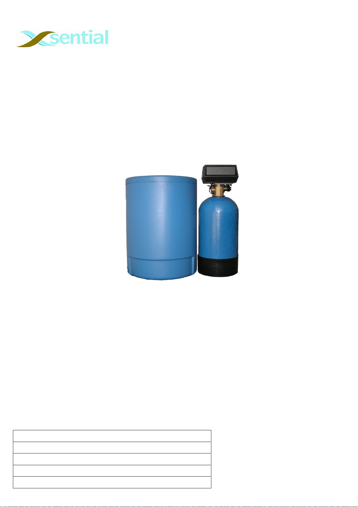
cylindrical tank is the brine tank. It is the tank where regular softener salt top up is required from time to time. So please
make sure it’s accessible at all times.
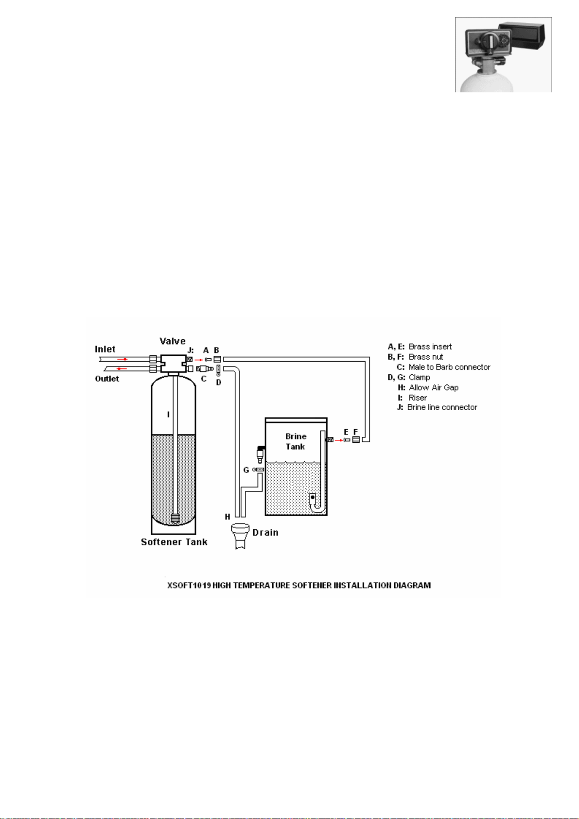
Step 2
Locate the cold/hot water (maximum water temperature is 65°C) supply and a nearby floor
drain. Ensure that the top distributor screen is attached to the bottom of the control
valve. Lubricate the o-ring on the bottom of the control valve that will seal with the tank
opening. Insert the riser pipe into the top distributor screen and then thread on the control
valve being careful not to cross thread it into the top tank threads. Hand tighten the control
valve on the tank until fitted snugly.
Step 3
Attach the Bypass valve (BSP Threads 3/4") to the control valve.
Step 4
Connect the inlet and outlet water lines. (Please note that the maximum working pressure for the system is 125psi. A
pressure reduction valve is strongly recommended). Run a drain line to a floor drain from the ½” connection on the control
valve. This should be no longer than 20 feet from the water softener. The drain line should be a flexible ½” i.d. plastic
which can be of vinyl or polyethylene type material and should be secured with a small clamp over the drain fitting. The
backwashing drain line will be under high pressure when the backwash cycle is working. Make sure the drain line is
secured. The drain line will need to drain into a floor drain.
CAUTION:PLEASE OBSERVE THE DIRECTION OF THE INLET AND OUTLET ARROW OF THE VALVE TO ENSURE THE SOFTENER IS PIPED
PROPERLY.
Step 5
First attach the brass nut to the tubing then put the brass insert inside the tubing (on both ends of the tube) and screw the
tubing and nut to the brass thread of the connector. Connect the clear brine line to the brine line connector of the control
valve. Attach the other end of the tube to the brine tank ensuring that both connections are tight.
NOTE:NEVER CONNECT THE DRAIN LINE DIRECTLY INTO THE FLOOR DRAIN.ALLOW AN AIR GAP BETWEEN THE DRAIN LINE AND
WASTE LINE TO PREVENT POSSIBILITY OF BACK SIPHONING.
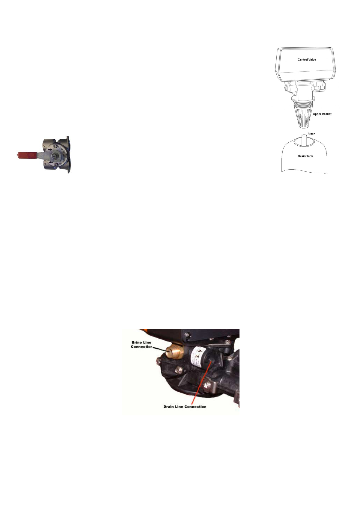
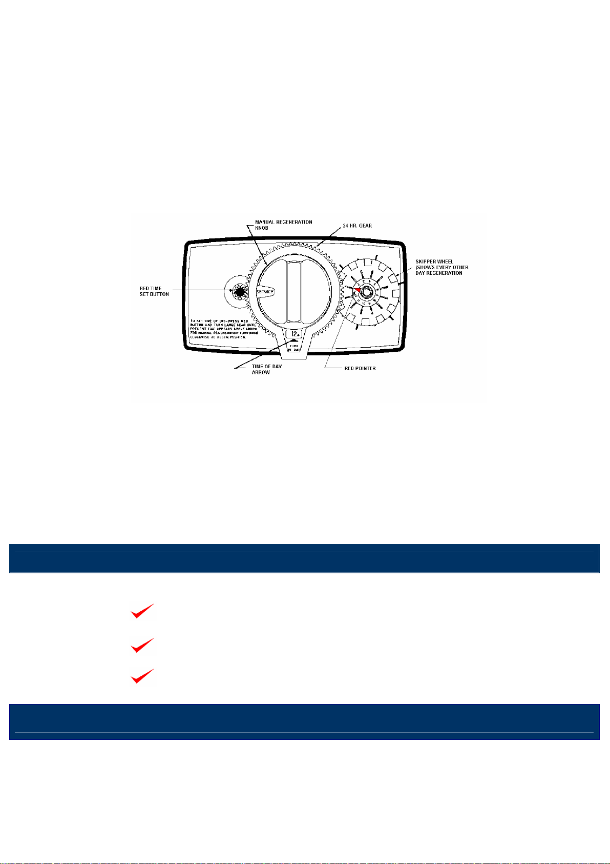
Step 6
Fill the resin tank with water by opening the bypass valve. Place the valve in the rapid rinse position to rinse the resin for 1
minute then back into a service position.
Step 7
Put one bag of 25kg softener salt and add about 8 litre of water into the brine tank (just above the water level) (use softener
salt because they are manufactured for water softener systems).
Diagram 2

Step 8
You can cycle the control valve into its various positions manually by turning the main valve control in a clockwise
direction. The main cycles are service, backwash, brine draw/slow rinse, rapid rinse, and brine refill. The default position is
Service. Please do not adjust the valve control to any other position.
Do not plug in the power point at this stage. Make sure that the bypass valve is set to bypass mode and slowly turn on the
main water supply until all pipes are pressurized. Open the bypass valve SLOWLY. Let the resin tank fill up completely
with water, then open the bypass valve the rest of the way. Check for any water leakage. Turn off the main water supply if
there is any water leakage. Reseal all the leaks and start above procedure again.
Step 9
Plug the power plug into a power socket. Set the correct time of day on the control valve by pushing the Red time set
button and rotate the 24 HR gear until the correct time. When the correct time of day appears, the unit will regenerate at
midnight.
PLEASE NOTE THAT THE SALT REGENERATION FREQUENCY HAS BEEN SET ACCORDING TO THE WATER
HARDNESS TESTED AND WATER CONSUMPTION GIVEN. DO NOT READJUST THE SKIPPER WHEEL.
For reference only
The frequency of regeneration is set by pushing out the pins on the Skipper wheel (12 pins). If every pin is pushed out,
then the unit will regenerate every night, every other pin, then every other night, etc. Estimate how much water is used on a
daily basis and then set the frequency accordingly.
Visit www.xsential.com.au to see more of Xsential’s products to suit various water feed appliances.
E
Es
ss
se
en
nt
ti
ia
al
l
P
Pr
ro
ot
te
ec
ct
ti
io
on
n
E
Es
ss
se
en
nt
ti
ia
al
l
S
Sa
av
vi
in
ng
g
X
Xs
se
en
nt
ti
ia
al
l
S
So
ol
lu
ut
ti
io
on
ns
s
SOLUTION FOR:
COFFEE MACHINES |ICE MAKERS |COMBI STEAMER OVENS |HOT WATER URN |DRINKING |DISHWASHER |POST-MIXER
Xsential Pty Ltd
78 Daly Street
Belmont Western Australia 6104
Ph: 1300 366 295 Fax: (08) 9228 3883
www.xsential.com.au 2010 Xsential Pty Ltd
Table of contents
Other Xsential Water Dispenser manuals
Popular Water Dispenser manuals by other brands

Spritzer
Spritzer D002 manual

Kenmore
Kenmore 625.34857 owner's manual

Whirlpool
Whirlpool WHES40 Installation and operation manual

North Star
North Star NSC42 Installation and operation manual

Grunbeck
Grunbeck softliQ:MD Series Operation manual

Haws
Haws H1011.8 Installation, operation & maintenance instructions