XtremeAIR XA41 Reference manual

XtremeAir GmbH, Harzstr.2, D-39444 Hecklingen
Document No.
SB-2013-002
Tel: +49 39267 60999 0, Fax: +49 39267 60999 20
www.xtremeair.de [email protected] Issue: A.01
DOA-Nr.: EASA.21J.360 Service Bulletin SB-2013-002
Date: 15.4.2013
Replaces Service Bulletin No. / Date:
Not applicable
Page 1 / 8
MANDATORY
Subject: Fuel Vent
Aircraft type affected: XA41 and XA42
Serial numbers affected: MSN 01 through 06, and 101 through 114
Compliance:Mandatory
Time of Compliance: next 100 hours
Purpose: To notify owners of above aircraft of a potential flight safety
condition.
Background: The transparent fuel vent hoses installed in the aircraft listed
above have unsatisfactory ageing characteristics.
The present service bulletin provides instructions for the
installation of improved fuel vent hoses.
Manpower: It is estimated approximately 25-30 man-hours will be required to
accomplish this bulletin.
Materials: The following material should be ordered through
10 m blue vent line
(1) ea. firewall assy. XA42-7130-180
(1) ea. thermal blanket XA42-7130-202
(1) ea. bulkhead fitting fuel XA42-2820-216
(2) ea. bulkhead fitting brake line XA42-3280-245
(1) ea. starter cable guide XA42-7100-206
in addition the following consumables are required:
•RTV 106 sealant
•Epple 33 adhesive
•Locking wire MS20995C-32, 0,8mm
Accomplishment instructions:
1. Disconnect the right hand (rh) and left hand (lh) aileron rod (XA42-2710-114) from aileron
bellcrank (XA42-2710-050) in the fuselage by removing the AN4-11 bolt connection.
2. Remove the rh/lh spade arms (XA42-5760-121).
3. Remove the sighting devices (XA42-5770-001).

XtremeAir GmbH, Harzstr.2, D-39444 Hecklingen
Document No.
SB-2013-002
Tel: +49 39267 60999 0, Fax: +49 39267 60999 20
www.xtremeair.de [email protected] Issue: A.01
DOA-Nr.: EASA.21J.360 Service Bulletin SB-2013-002
Date: 15.4.2013
Replaces Service Bulletin No. / Date:
Not applicable
Page 2 / 8
4. Remove the fuel-selector-linkage (XA42-2840-100).
Disconnect the electric cables at the wing.
Remove the fuel line cap (XA42-5370-241) on the right side.
5. Disconnect the fuel lines and the vent hose from the fuel tank access covers rh/lh
(XA42-2820-151/154).
6. Remove the longeron connectors (XA42-5320-239).
7. Remove the main bolts (Front bolts (XA42-5320-250), rear bolts (XA42-5320-340))) and
remove the wing from the spar bridge.
8. Remove the glued in fuel line cover (XA42-5370-240).
9. Remove the fuel vent hose from the tank wall bushing carefully with a cutter knife and remove
the excess glue.
10.Heat the new hose end (100-150°C) and push it 7mm over the tank wall fitting. Check the
area of the fuel line for foreign objects.
11.Bond the cover for the fuel line in the forward lower R/H fuselage with RTV 106.
Picture 1

XtremeAir GmbH, Harzstr.2, D-39444 Hecklingen
Document No.
SB-2013-002
Tel: +49 39267 60999 0, Fax: +49 39267 60999 20
www.xtremeair.de [email protected] Issue: A.01
DOA-Nr.: EASA.21J.360 Service Bulletin SB-2013-002
Date: 15.4.2013
Replaces Service Bulletin No. / Date:
Not applicable
Page 3 / 8
12.Change the fuel vent hose in the L/H forward compartment
13.Remove the wing tank vent hose from the tank wall fitting with a cutter knife. (Picture 3, Nr.1)
Attention: Do not damage the fittings.
14.Heat the new hose end (100-150°C) and push it 7mm over the tank wall fitting.
15.Remove the second vent hose from the tank wall fitting with a cutter knife. (Picture 3, Nr.3)
16.Remove the vent hose from the landing gear cover and from the fuselage. (Picture 3, Nr.2)
Picture 2
1
2
Picture 3
1
1
1
3

XtremeAir GmbH, Harzstr.2, D-39444 Hecklingen
Document No.
SB-2013-002
Tel: +49 39267 60999 0, Fax: +49 39267 60999 20
www.xtremeair.de [email protected] Issue: A.01
DOA-Nr.: EASA.21J.360 Service Bulletin SB-2013-002
Date: 15.4.2013
Replaces Service Bulletin No. / Date:
Not applicable
Page 4 / 8
17.Remove the vent hose from the fuel pump carefully with a cutter knife. (Picture 4)
Attention: Do not damage the fitting.
18.Transfer the length of the old hoses to the new hoses.
19.Install all new vent hoses to the appropriate fittings.
20.Remove the hand-hole covers (XA42-2820-151/154) in the wing root ribs.
21.Remove the vent pipe (XA42-2820-218) from the cover and remove the clear vent hose with
a cutter knife.
22.Install the new blue hose.
Attention:The hose must be pushed on the pipe minimum 15 mm on both sides!
Additionally wire lock using 0,8mm MS20995C-32 (Pictures 5 and 6)
23.Clean and degrease the cover sealing surfaces with acetone.
24.Reinstall the cover lh/rh (XA42-2820-151/154) with Epple 33. Install all bolts (Maintenance
Manual 20-10-02), torque:11Nm and secure with wire lock 0,8mm "MS20995C-32".
Picture 4
Picture 6
wire lock
Picture 5

XtremeAir GmbH, Harzstr.2, D-39444 Hecklingen
Document No.
SB-2013-002
Tel: +49 39267 60999 0, Fax: +49 39267 60999 20
www.xtremeair.de [email protected] Issue: A.01
DOA-Nr.: EASA.21J.360 Service Bulletin SB-2013-002
Date: 15.4.2013
Replaces Service Bulletin No. / Date:
Not applicable
Page 5 / 8
25.Remove the wiring harness from engine and engine mount and mark all separated
connections.
26.Remove all engine controls (throttle, mixture and governor) from engine and engine mount.
27.Remove and mark all separated cables and hoses between engine mount and fuselage.
28.Jack up the fuselage at the spar bridge.
29.Remove the landing gear lh/rh from the engine mount.
30.Secure the engine with lifting belt and remove the Slick starter and smoke valve.
31.Disconnect the engine mount from fuselage and lift the engine with engine mount.
Attention: Do not damage the oil cooler.
32.Remove the service cover (XA42-7130-170) from the fire wall.
33.Remove all fittings from the fire wall.
34.Cut open the RTV-joint between fire wall and fuselage.
35.Remove the protecting hose of the cable harness about 20cm.
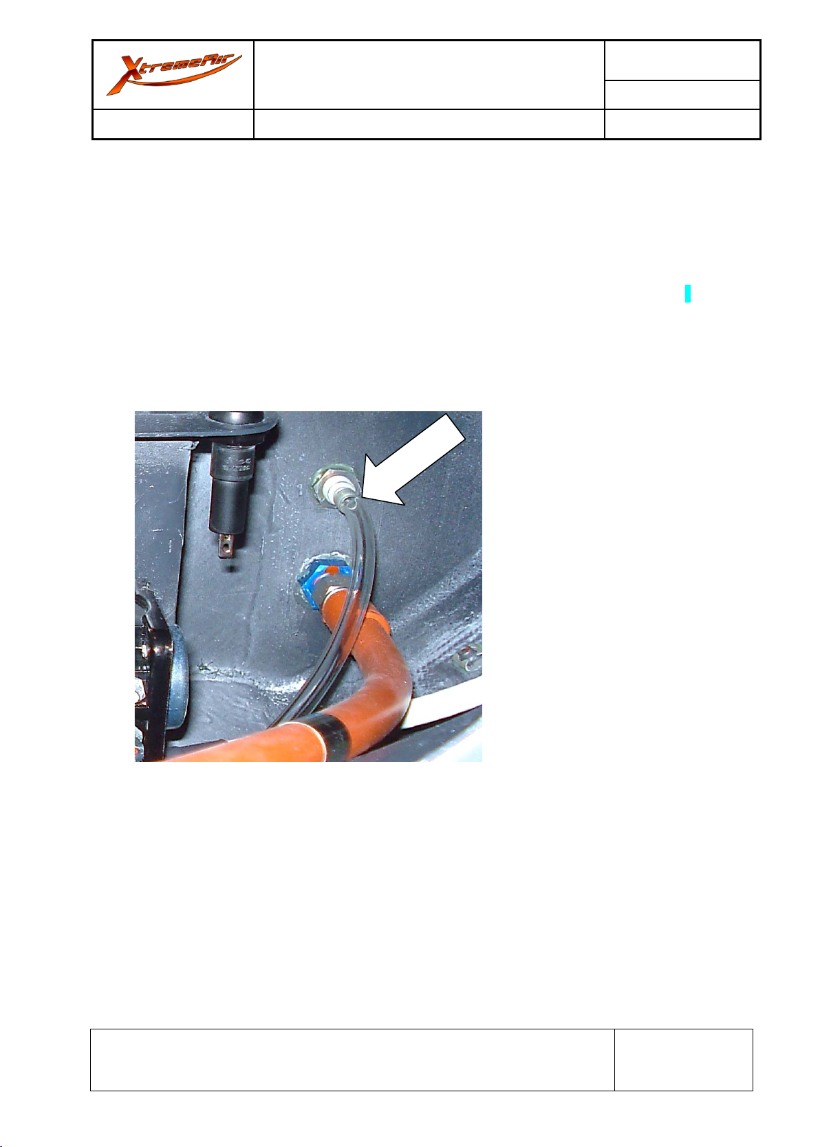
36.Disconnect the manifold pressure hose and the smoke hose (XA42-8500-114) behind the fire
wall.
37.Remove the fire wall plate (XA42-7130-200) and the fiberfrax fire protection mat (XA42-7130-
202) to the right hand side.
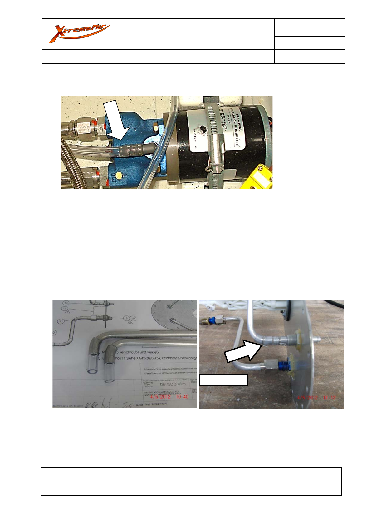
38.Remove the lh/rh vent hoses.
39.Remove all remaining RTV sealant.
40.Connect the new blue vent hoses and seal with RTV 106.
41.Clean all bonding surfaces with acetone. Bond the thermal blanket
(XA42-7130-210) to the tank with RTV 106, position with fire wall plate (XA42-7130-200).
42.Fix the top flanges (XA42-7130-221), bottom flanges (XA42-7130-222), small spacer (XA42-
7130-260), middle spacer (XA42-7130-261) and large spacer (XA42-7130-262), above their
cut-out holes in the fire wall plate (XA42-7130-200) with superglue.
43.Clean the fire wall with acetone. Apply RTV 106 around the fire wall plate (XA42-7130-200)
and around the fuselage.
Attention:Do not apply RTV 106 at the engine mount interface points.
44.Bond fiberfrax protection blanket (XA42-7130-202) to the fuselage. Position the fire wall at the
blanket. All holes in the fuselage must be aligned.
Apply RTV 106 sealant around the fire wall sheet to cover the fiberfrax protection blanket
(XA42-7130-202). Remove the excess RTV 106 immediately.
45.Temporarily fix the fire wall plate (XA42-7130-200) with tape while the RTV 106 cures.
46.Install all parts in reverse order.
47.Install the service cover (XA42-7130-160) with RTV.
48.Install the engine with engine mount using new nuts and bolts.
(Maintenance Manual 20-10-02)

XtremeAir GmbH, Harzstr.2, D-39444 Hecklingen
Document No.
SB-2013-002
Tel: +49 39267 60999 0, Fax: +49 39267 60999 20
www.xtremeair.de [email protected] Issue: A.01
DOA-Nr.: EASA.21J.360 Service Bulletin SB-2013-002
Date: 15.4.2013
Replaces Service Bulletin No. / Date:
Not applicable
Page 6 / 8
49.Install all removed hoses and controls.
50.Install and connect the smoke valve and Slick starter. (Maintenance Manual 20-10-02)
51.Lift the fuselage and install the landing gear lh/rh with the XA42-3210-230 bolts and secure
them with safety wire.
Install both vent hoses into the landing gear cover.
Attention: Position and fix the cover after installation of the wing.
52.Torque all bolts (79Nm) and secure with safety wire 0,8mm "MS20995C-32".
53.Install the break pipes. (Pictures 8)
54.Torque all screw fittings (Maintenance Manual 20-10-02).
Reinstall the wing:
Picture 8

XtremeAir GmbH, Harzstr.2, D-39444 Hecklingen
Document No.
SB-2013-002
Tel: +49 39267 60999 0, Fax: +49 39267 60999 20
www.xtremeair.de [email protected] Issue: A.01
DOA-Nr.: EASA.21J.360 Service Bulletin SB-2013-002
Date: 15.4.2013
Replaces Service Bulletin No. / Date:
Not applicable
Page 7 / 8
55.Temporarily secure the electrical cable on the wing lh/rh with tape. (Picture 9)
56.Position the aileron rod inside the wing as shown in picture 10.
Attention:Do not damage the aileron rod .
57.Fix all cables and hoses in the fuselage. Temporarily fix the control stick in neutral position.
58.Remove the fuel selector linkage (XA42-2840-100)
59.Install the wing and use the main bolts: Front bolts (XA42-5320-250), rear bolts (XA42-5320-
340).
60.Install the lower fuselage longeron connectors (XA42-5320-239).
Secure the opposite bolts with safety wire 0,8mm "MS20995C-32".
Picture 9
Picture 10

XtremeAir GmbH, Harzstr.2, D-39444 Hecklingen
Document No.
SB-2013-002
Tel: +49 39267 60999 0, Fax: +49 39267 60999 20
www.xtremeair.de [email protected] Issue: A.01
DOA-Nr.: EASA.21J.360 Service Bulletin SB-2013-002
Date: 15.4.2013
Replaces Service Bulletin No. / Date:
Not applicable
Page 8 / 8
61.Install the fuel hoses and the vent hoses to tank cover lh/rh as per Maintenance
Manual 20-10-02.
62.Connect all electrical cable. Install the fuel line cover on the right side with RTV 106.
63.Install the fuel selector linkage (XA42-2840-100).
64.Install the spade arms rh/lh (XA42-5760-121) and the sighting devices (XA42-5770-001).
65.Install the aileron rod rh/lh (XA42-2710-114) to the aileron bellcrank (XA42-2710-050)
in the fuselage in reverse order. Secure the bolt with a new 2x12 splint.
Report the accomplishment of this service bulletin via email to schuelter@xtremeair.de, stating
aircraft serial number and registration number.
Approval: The technical information contained in this document has been approved under the
authority of EASA Design Organisation Approval no. EASA.21J.360.
Picture 11
Picture 12
Other manuals for XA41
1
This manual suits for next models
1
Table of contents
Other XtremeAIR Aircraft manuals
Popular Aircraft manuals by other brands

FLYSURFER
FLYSURFER CONNECT2 user manual

Skywalk
Skywalk HYPE Owner's manual & operating instructions

AEROPRAKT
AEROPRAKT AEROPRAKT-32 Pilot operating handbook

DG Flugzeugbau
DG Flugzeugbau DG-500MB Flight manual

QuiQue's Aircraft
QuiQue's Aircraft Semi Scale Yak-54 Assembly manual

ICARO
ICARO ICE2XC user manual