3
1. Read these instructions.
2. Keep these instructions.
3. Heed all warnings.
4. Follow all instructions.
5. Do not use this apparatus near water.
6. Clean only with dry cloth.
7. Do not block any ventilation openings. Install in accordance
with the manufacturer’s instructions.
8. Do not install near any heat sources such as radiators, heat
registers, stoves, or other apparatus (including ampliers)
that produce heat.
9. Do not defeat the safety purpose of the grounding type plug.
The grounding plug has two blades and a third grounding
prong. The third prong is provided for your safety. If the pro-
vided plug does not t into your outlet, consult an electrician
for replacement of the obsolete outlet.
10. Protect the power cord from being walked on or pinched
particularly at plugs, convenience receptacles, and the point
where they exit from the apparatus.
11. Only use attachments/accessories specied by the
manufacturer.
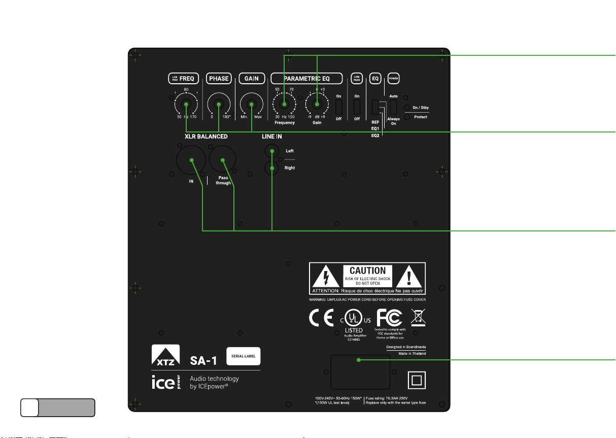
See markings
on the product.
12. Use only with cart, stand, tripod, bracket, or table specied by
the manufacturer, or sold with the apparatus. When a cart is
used, use caution when moving the cart/apparatus combina-
tion to avoid injury from tip-over.
13. Unplug this apparatus during lightning storms or when unused
for long periods of time.
14. Refer all servicing to qualied service personnel. Servicing is
required when the apparatus has been damaged in any way,
such as power supply cord or plug is damaged, liquid has
been spilled or objects have fallen into the apparatus, the ap-
paratus has been exposed to rain or moisture, does not oper-
ate normally, or has been dropped.
15. The appliance coupler is used as the disconnect device and
shall remain readily operable.
Important Safety Instructions
The exclamation point, within an equilateral triangle, is intended to alert the user to the presence
of important operating and maintenance (servicing) instructions in the literature accompanying
the product.
The lightning ash with arrowhead symbol within an equilateral triangle is intended to alert the
user to the presence of uninsulated “dangerous voltage” within the product’s enclosure that may
be of sucient magnitude to constitute a risk of electrical shock to persons.
WARNING! To reduce the risk of re or electric shock, do not ex-
pose this apparatus to rain or moisture.
WARNING! This apparatus shall not be exposed to dripping or
splashing, and no objects lled with liquids, such as vases, shall be
placed on the apparatus.
WARNING! This apparatus shall be connected to a MAINS socket
outlet with a protective earthing connection.
DANGER! No user serviceable parts inside. Service is to be
performed only by XTZ.