Xycom CHIP4e+ User manual

1
CHIP4e+
Compact High-Integration
5x86 Platform with
Ethernet
P/N 128767-001A
2002 XYCOM, INC. Printed in the United States of America

CHIP4e+ Manual
2
Revision Description Date
A Manual Released 3/98
B Touchscreen Updates 7/02
Trademark Information
Brand or product names are registered trademarks of their respective owners.
AMD is a registered trademark and 5x86 is a trademark of Advanced Micro Devices Inc.
Copyright Information
This document is copyrighted by Xycom Incorporated (Xycom) and shall not be reproduced or copied
without expressed written authorization from Xycom.
The information contained within this document is subject to change without notice.
xycom
Technical Publications Department
750 North Maple Road
Saline, MI 48176–1292
734-429-4971 (phone)
734-429-1010 (fax)

3
Table of Contents
Chapter 1 – Module Overview....................................................................................................................5
Module Features........................................................................................................................................................5
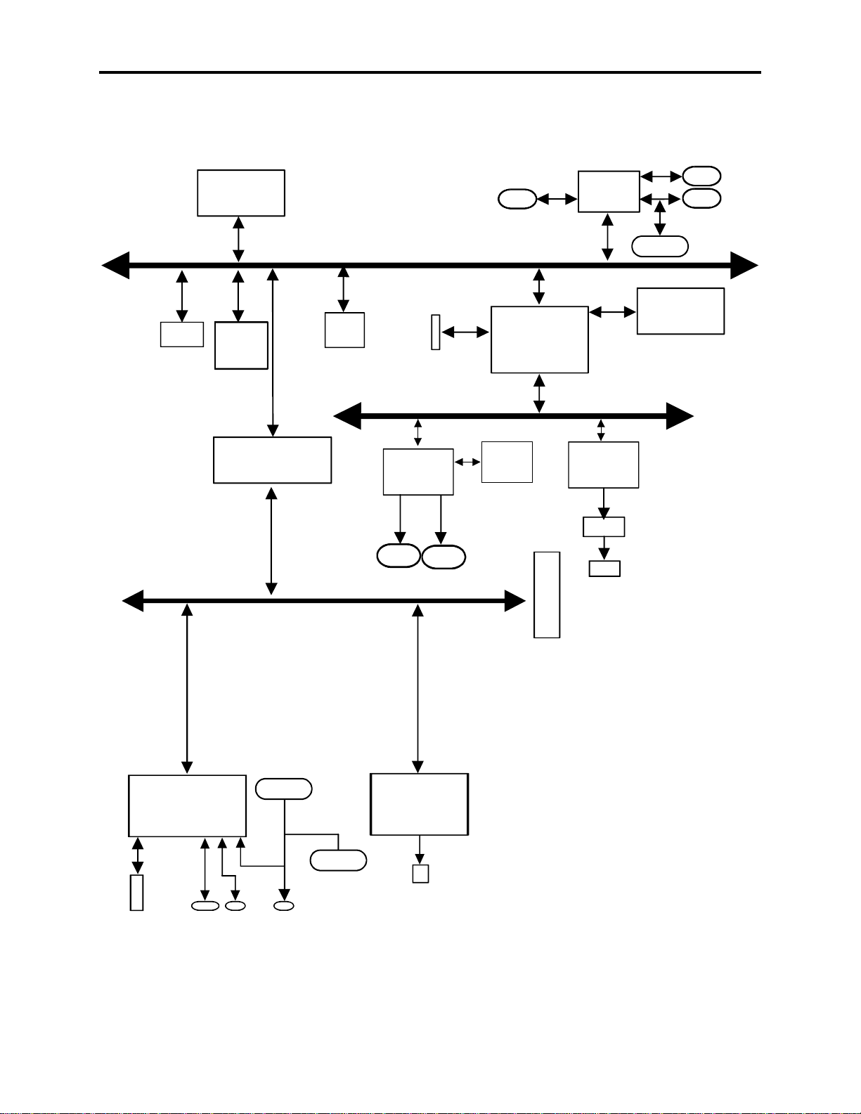
Architecture...............................................................................................................................................................6
CPU........................................................................................................................................................................7
PCI Bus Interface ...................................................................................................................................................7
SVGA Graphics Controller..................................................................................................................................7
Fast IDE controller ..............................................................................................................................................7
Ethernet Controller ..............................................................................................................................................7
On-board Memory..................................................................................................................................................8
DRAM.................................................................................................................................................................8
Flash BIOS ..........................................................................................................................................................8
Non-Volatile SRAM or DOC2000 (optional)......................................................................................................8
Serial and Parallel Ports..........................................................................................................................................9
Keyboard Ports.......................................................................................................................................................9
Mouse Port ...........................................................................................................................................................10
IR Interface...........................................................................................................................................................10
Flat-panel Interfaces.............................................................................................................................................10
Floppy and Hard Drives .......................................................................................................................................10
Keypad Interface ..................................................................................................................................................11
Expansion Options................................................................................................................................................11
Environmental Specifications..................................................................................................................................11
Hardware Specifications..........................................................................................................................................12
Chapter 2 – Installation.............................................................................................................................13
Configuration Options.............................................................................................................................................14
Jumper Settings.....................................................................................................................................................14
System Interrupts..................................................................................................................................................15
DMA Mapping .....................................................................................................................................................15
Memory Map........................................................................................................................................................16
I/O Map ................................................................................................................................................................17
Registers..................................................................................................................................................................18
Register 231h – CPU LED Port............................................................................................................................18
Register 233h – Flash BIOS Control....................................................................................................................19
Register 234h – I/O Port Location........................................................................................................................19
Offset Registers ....................................................................................................................................................20
Offset 0 Page Register for Programming (Port Address)...................................................................................20
Offset 1 Page Register for Programming (Port Address +1)..............................................................................20
Connectors...............................................................................................................................................................21
Parallel Port Connector (PARCOM2)..................................................................................................................21
Serial Port Connectors..........................................................................................................................................22
COM1 Connector (COM1)................................................................................................................................22
COM2 Connector (PARCOM2)........................................................................................................................23
PS/2 Keyboard and Mouse Port Connector (KBMS1).........................................................................................24
Internal Keyboard Connector (KYBD1)...............................................................................................................24
VGA Connector (VGA2)......................................................................................................................................24
External Floppy Drive Connector (FDD2)...........................................................................................................24
Internal LED Connector (LEDMSC1)..................................................................................................................25
FPGA Program Connector (J5) ............................................................................................................................26
IDE Connector (HDD2) .......................................................................................................................................26
Power Connectors (DCPWR1).............................................................................................................................27
Touch Control Connector (TCTRL1)...................................................................................................................27

CHIP4e+ Manual
4
Touch Connector (TCH1).....................................................................................................................................28
STN Flat-Panel Connector (FPNL1) ....................................................................................................................28
TFT Flat-Panel Connector (FPNL2).....................................................................................................................29
Backlight Inverter Connector (DCINV1).............................................................................................................29
AC Input Connector (ACIN1)..............................................................................................................................30
AC Supply Connector (ACOUT1) .......................................................................................................................30
H8 Boot Program (PROGH3) ..............................................................................................................................30
Ethernet Connector (ETHER1) ............................................................................................................................30
PC/104 Connector (P7 and P8).............................................................................................................................30
Keypad Connector (KEYPAD1) ..........................................................................................................................32
Moving through the Menus .....................................................................................................................................33
BIOS Main Menu....................................................................................................................................................34
IDE Adapter 0 Master and Slave Submenu..........................................................................................................35
Memory Shadow Submenu...................................................................................................................................36
Boot Sequence Submenu......................................................................................................................................37
Numlock Submenu ...............................................................................................................................................38
Advanced Menu....................................................................................................................................................39
Integrated Peripherals Submenu...........................................................................................................................40
Advanced Chipset Control Submenu....................................................................................................................41
Security Menu .........................................................................................................................................................42
Exit Menu................................................................................................................................................................43
BIOS Compatibility.................................................................................................................................................44
Appendix A – DRAM Installation..............................................................................................................45
Appendix B – Video Modes......................................................................................................................47
Standard Modes.......................................................................................................................................................47
Extended Modes......................................................................................................................................................48
Windows®3.1..........................................................................................................................................................48
Windows 95.............................................................................................................................................................48
Windows NT® 3.5 ..................................................................................................................................................49
OS/2 Warp 3............................................................................................................................................................49
Index.......................................................................................................................................................................50

5
Chapter 1 – Module Overview
The Xycom Compact High-Integration 5x86™ Platform with Ethernet (CHIP4e+) is
designed for use in Xycom’s line of flat-panel industrial personal computers. The
CHIP4e+ is optimized in design, layout, and features for use with these flat-panel
computer systems. This integrated design approach allows Xycom industrial PC/ATs
to incorporate “Big PC” features in an extremely compact package. These “Big PC”
features include a 133 MHz CPU, PCI-bus SVGA controller, PCI IDE controller,
PCI 10BASE-T/100BASE-TX controller, infrared port, and integrated touch screen.
Module Features
The CHIP4e+ offers the following features:
•133 MHz Am5x86 CPU
•4 to 64 Mbytes EDO DRAM
•PCI local bus SVGA controller
•Jumper-selectable flat-panel interface that supports STN and TFT formats up
to 640x480x16M
•CRT interface that supports formats up to 1024x768x256
•1Mbyte video memory
•PCI fast IDE controller
•Two 16550-compatible serial ports
•UART1: RS-232 or RS-485
•UART2: RS-232 port, Infrared (IR), or touch screen
•Centronics-compatible parallel port
•PCI 10BASE-T/100BASE-TX Ethernet controller
•PC/104 support
•Floppy controller and external floppy connector
•PS/2 mouse and keyboard ports
•Real-time clock and battery
•Touch screen, keypad, and LED interfaces
•DOC2000 or 32Kx8 and 128Kx8 non-volatile SRAM support

CHIP4e+ Manual
6
Architecture
This section describes the architecture of the CHIP4e+ processor module.
CPU Local Bus
PCI Bus
ISA Bus
Flo
ppy
Flash
BIOS
LPT1 COM1 COM2
LED
Flat
Panel
SRAM
EPROM
DOC2000
KBD
Mouse
Mag
10/100BT
PC/104
IRDA
Touch
1Mbyte
DRAM
AM5x86
CPU
H8
Keyboard
Controller
Touch
4 to 64Mbytes
DRAM
M1489
CPU to PCI
RTC
EIDE
65550
VGA
M1487
CPU to ISA 82558
Ethernet
Super I/O
37C669 FPGA
Ports, FLASH
Keypad
CRT
Figure 0-1. CHIP4e+ Functional Block Diagram

7
CPU
The CHIP4e+ incorporates an AMD®5x86 processor with a CPU clock that runs
quadrupled at 133 MHz with a 33 MHz external bus. The unified 16 Kbyte write-
back cache technology minimizes the time the CPU core spends waiting for data or
instructions, accelerating business and multimedia applications.
PCI Bus Interface
The FinALI chipset integrates a high-performance CPU-to-PCI interface capable of
accelerated data transfers. The interface allows 32-bit master and slave PCI devices.
SVGA Graphics Controller
The PCI bus SVGA graphics controller supports CRTs and flat-panel displays with 1
Mbyte video DRAM. It supports resolutions of 640x480 with 16M colors; 800x600
with 64K colors; and 1024x768 with 256 colors.
Fast IDE controller
The high-speed local bus IDE controller supports programmed I/O (PIO) modes 0-4.
It also provides 4x32-bit read-ahead buffer and 4x32-bit write-post buffer support to
enhance IDE performance.
Caution
The IDE controller supports enhanced PIO modes, which reduce the
cycle times for 16-bit data transfers to the hard drive. Check with your
drive manual to see if the drive you are using supports these modes. The
higher the PIO mode, the shorter the cycle time. As the IDE cable length
increases, this reduced cycle time can lead to erratic operation. As a
result, it is in your best interest to keep the IDE cable as short as
possible.
Select the PIO modes in the BIOS setup (refer to Chapter 3). The
autoconfigure classifies the drive connected if the drive supports the
auto ID command. If you experience problems, change the PIO to
standard.
Ethernet Controller
The CHIP4e+ contains a state-of-the-art 10BASE-T/100BASE-TX Ethernet
controller with a 32-bit PCI bus-mastering interface to support 100-Mbits per second
bus transfers. The controller serves as both a PCI master and slave. The Ethernet
connector (ETHER1) provides auto-sensing for 10BASE-T and 100BASE-TX
connections.

CHIP4e+ Manual
8
On-board Memory
DRAM
The CHIP4e+ has one 72-pin SIMM memory site, providing up to 64 Mbytes of
DRAM. Populate the memory site with standard fast page mode memory or extended
data out memory (EDO). EDO memory improves DRAM read performance.
Flash BIOS
The CHIP4e+ board provides a Flash BIOS location for system and video ROM.
Table 0-1 describes the Flash memory map.
Table 0-1. Flash Memory Map
Device Address Software System Address
60000-7FFFFh System BIOS E0000-FFFFFh (also FFFE0000-
FFFFFFFFh)
10000-5FFFFh Undefined
00000-0FFFFh Video BIOS C0000-CFFFFh
Non-Volatile SRAM or DOC2000 (optional)
Socket U25 is a 32-pin ROM site that provides an option for installing non-volatile
SRAM or DiskonChip 2000 modules. You must specify which option you are
installing on the BIOS Setup Advanced menu (refer to Chapter 3 for more
information on the BIOS Setup menus).
Note
You may only install SRAM or DOC2000 in socket U25; you cannot
install both.
Non-volatile SRAM contains a built-in battery and battery backup circuitry. Battery
life is approximately seven years in the absence of VCC. Socket U25 supports
32Kx8 and 128Kx8 memory sizes. BIOS defines the location of SRAM as CC000.
DiskOnChip 2000 (DOC2000) is a Flash memory module. It contains an expansion
BIOS that allows Flash memory to emulate a disk drive when the corresponding
option is enabled in the BIOS Setup Advanced menu. If the system already
incorporates a C: drive (IDE), DOC2000 becomes the D: drive. When installed, the
DOC2000 module occupies memory address CC000-CFFFFh.

9
Serial and Parallel Ports
PC/AT peripherals include two high-speed, RS-232C, 16550-compatible serial ports
and one bi-directional Centronics-compatible parallel port.
UART1 (COM1) accepts an RS-232 or a RS-485 connection (you can only use one
connection at a time). UART2 (COM2) can be used for one of the following three
options:
•RS-232 out the 25-pin DB connector
•Touch screen controller interface
•Infrared (IR) interface
Use the BIOS setup menus to configure the port as a serial or infrared port. You can
use this port as both a serial and IR interface by allowing software to control the
connection.
Note
You cannot use UART2 as a serial and IR port at the same time.
If the touch screen controller is jumpered to use UART2 as a serial device, the 25-
pin DB connector cannot be used to interface to a device. These lines are combined
internally.
Note
The BIOS setup menus for UART2 must be set to standard operation to
use the touch screen controller on UART2.
Keyboard Ports
The keyboard port is routed to two separate connectors. One is a PS/2 connector,
allowing the keyboard to be routed out the side of the unit; the other connector
allows the keyboard to be routed to the front of the unit.
A polyswitch protects the +5 V on the keyboard port. This device opens if the +5 V
is shorted to GND. Once you remove the shorting condition, the polyswitch allows
current flow to resume.
Note
You can only use one keyboard port at a time.

CHIP4e+ Manual
10
Mouse Port
The CHIP4e+ supports two mouse ports. The external mouse port is routed to the
PS/2 mouse connector; the internal mouse port is routed to the touch screen
controller. If touch screen drivers are loaded, the external mouse port is disabled.
Both the external port and the touch screen controller may be plugged in at the same
time. However, the driver loaded may impair the operation of one of the ports. If the
Microtouch mouse drivers are loaded, the external mouse port will use these drivers.
Note
When using the Xycom touchscreen controller (PIN 140554), the
CHIP4e+ will behave the same. If using a PS/2 mouse is desired, install
the Touch-Base touch driver in serial mode. In serial mode, the
controller will use a COM port and free the PS/2 mouse port. Please
follow the installation instructions on the Xycom documentation.
A polyswitch protects the +5 V on the mouse port. This device opens if the +5 V is
shorted to GND. Once you remove the shorting condition, the polyswitch allows
current flow to resume.
IR Interface
The IR interface, which uses UART2, is a half-duplex serial port capable of 115
Kbaud transfer rates. It also supports two transfer formats: IrDA and ASKIR. You
must load software to support communication between two devices.
Flat-panel Interfaces
The CHIP4e+ incorporates two flat-panel connectors. The STN connector interfaces
directly to STN flat panels. It provides a substrate voltage (VEE) of 34 volts, contrast
control, and frame rate modulation to allow 4096 colors to be displayed. The TFT
connector interfaces directly to TFT flat panels.
The flat-panel type is jumper selectable. Refer to Chapter 2 for jumper settings.
Floppy and Hard Drives
The CHIP4e+ can interface to a floppy drive via the external floppy connector. To
connect a floppy drive to the external connector after power up, you must specify the
floppy drive as a 1.44 Mbyte drive, and disable the floppy check option in the BIOS
setup menus. If this is not done, the system will generate a floppy drive error during
the Power On Self Test (POST).
The PCI-to-IDE interface supports one hard drive via the on-board IDE controller.
Caution
The total IDE cable length must not exceed 18 inches.

11
Keypad Interface
The CHIP4e+ provides a keypad interface. A connector supports up to a 10x8 scan
matrix, which is combined with the keyboard bit stream by the keyboard controller.
Expansion Options
The CHIP4e+ provides a location to stack up to two PC/104 cards (refer to the
PC/104 Connector section in Chapter 2).
Environmental Specifications
Table 0-2. Environmental Specifications
Characteristic Specification
Temperature
Operating
Non-operating 0° to 55° C (32° to 131° F)
-20° to 60°C (-4° to 140°F)
HumidityOperating
Non-operating 20% to 80% RH non-condensing
20% to 80% RH non-condensing
Altitude Operating
Non-operating Sea level to 10,000 feet (3048 m)
Sea level to 40,000 feet (12192 m)
VibrationFrequency
Operating
Non-operating
5 to 2000 Hz
0.006" peak-to-peak displacement
1.0g maximum acceleration
0.015" peak-to-peak displacement
2.5 g maximum acceleration
Shock Operating
Non-operating 15g peak acceleration, 11 msec duration
30g peak acceleration, 11 msec duration

CHIP4e+ Manual
12
Hardware Specifications
Table 0-3. Hardware Specifications
Characteristic Specification
Power Specifications
+12V
-12V
+5V
Typical Maximum
25ma 50ma
25ma 50ma
2.50 A 3.0A
CPU speed 133 MHz
PCI Super VGA Graphics
Controller 1 Mbyte video DRAM
STN and TFT support
640x48016M colors
800x60064K colors
1024x768 256 colors
Serial Ports (2) 16550 compatible
UART1: RS-232 or RS-485
UART2: RS-232, IR, or touch-screen
Parallel Interface Centronics compatible
On-board memory 4 to 64 Mbytes EDO DRAM
PCI Ethernet interface 10BASE-T/100BASE-TX
PCI IDE Primary connector
Floppy drive 1.44 Mbyte (external option)
Expansion Options PC/104 (-5 V is not supported)

13
Chapter 2 – Installation
This chapter provides information on configuring the CHIP4e+ processor module.
Figure 0-1 illustrates jumper and connector locations on the CHIP4e+.
Figure 0-1. CHIP4e+ Jumper and Connector Locations

CHIP4e+ Manual
14
Configuration Options
Jumper Settings
Table 2-1 lists the module’s jumpers, and their default positions and functions. The
jumpers marked Access are at the top of the board for easy customer access.
Table 0-1. CHIP4e+ Jumpers
Jumper Position Function
J1 A ü
BPush button reset switch disabled (Access)
Push button reset switch enabled
J2 A ü
BCMOS OK (Access)
Clear CMOS
J3* A
BAuto Detect (Access)
CRT selected
J4 Aü
BNormal
Program keyboard controller
J6 Aü
BBoot Flash enabled
EPROM boot enabled
J7* A
B+5V panel logic
+3.3V panel logic
(see Table 2-2)
J8 A ü
BVGA enabled
VGA disabled
J9-J11* A
BPanel type select (see Table 0-2)
üIndicates the default settings.
*Flat panel/CRT setting will dictate default settings on J3, J7, and J9-J11.

15
Table 0-2. Jumper-Selectable Panel Type
Panel Type J7 J9 J10 J11
Sharp TFT 421/344
640x480
+5V
ABB B
Kyocera STN
640x480
+5V
AAB B
Kyocera STN
1024x768
+5V
ABA B
Sharp TFT
1024x768
+5V
AAA B
Kyocera STN
800x600
+3.3V
BBB A
Sharp TFT
800x600
+3.3V
BAB A
System Interrupts
Table 0-3 describes the interrupts used on the CHIP4e+.
Table 0-3. System Interrupts
Interrupt Function
IRQ0 System Timer
IRQ1 Keyboard
IRQ2 Cascade
IRQ3 Serial Port*
IRQ4 Serial Port*
IRQ5 Parallel Port*
IRQ6 Floppy Controller
IRQ7 Parallel Port*
IRQ8 Real-Time Clock
IRQ9 Unused
IRQ10 Serial Port*
IRQ11 Serial Port*
IRQ12 Mouse Port
IRQ13 Math Coprocessor
IRQ14 Fixed Disk
IRQ15 Unused
*BIOS setup controlled
The BIOS setup menu controls the serial and parallel port interrupts. You can map
the two serial ports to any two of the following interrupts: 3, 4, 10, or 11. The
defaults are interrupts 3 and 4. This leaves IRQ10 and IRQ11 unused. You can map
the parallel port to IRQ5 or IRQ7.
DMA Mapping
Table 0-4. DMA Channels
DMA Function

CHIP4e+ Manual
16
DMA Function
DMA0 Unused (Could be used for EPP/ECP parallel port option)
DMA1 Unused
DMA2 Floppy Controller
DMA3 Unused (Could be used for EPP/ECP parallel port option)
DMA5 Unused
DMA6 Unused
DMA7 Unused
DMA channels 0-3 are 8-bit; 5-7 are 16-bit. When the ECP option is enabled one of
the 8-bit DMA channels is used.
Memory Map
Table 0-5 shows the CHIP4e+ memory map. The I/O designation refers to memory
viewed as part of the AT bus.
Table 0-5. Memory Map
Address Range (hex) Size Device
FFFE0000 - FFFFFFFF 128 Kbytes System BIOS
F8000000 - FFFEFFFF ~128 Mbytes Allocated to PCI bus by BIOS or operating system
80000000 - F7FFFFFF 15 x 128 Mbytes 128 Mbytes blocks of F8000000-FFFFFFFF
(shadowed 15 times)
08000000 - 7FFFFFFF 15 x 128 Mbytes 128 Mbytes blocks of 0-07FFFFFF (shadowed 15 times)
04000000 - 07FFFFFF 64 Mbytes Allocated to PCI bus by BIOS or operating system
00100000 - end of DRAM DRAM
000F0000 - 000FFFFF 64 Kbytes System BIOS
000E0000 - 000EFFFF 64 Kbytes System BIOS
000D0000 - 000DFFFF 64 Kbytes AT bus I/O
000CC000- 000CFFFF 16 Kbytes DOC2000 or Battery-backed SRAM option
000C0000 - 000CBFFF 48 Kbytes VGA BIOS
000A0000 - 000BFFFF 128 Kbytes VGA DRAM memory
00000000 - 0009FFFF 640 Kbytes DRAM

17
I/O Map Table 0-6 depicts the CHIP4e+’s I/O map. It contains the IBM AT architecture I/O
ports, as well as some additions.
Table 0-6. I/O Map
Hex Range Device
000-01F DMA controller 1, 8237A-5 equivalent
020-021 Interrupt controller 1, 8259 equivalent
022 M1489/M1487 configuration index register
023 M1489/M1487 configuration data register
025-02F Interrupt controller 1, 8259 equivalent
040-05F Timer, 8254-2 equivalent
060-06F 8742 equivalent (keyboard)
070-07F Real time clock bit 7 NMI mask
080-091 DMA page register
092 Reset/ Fast Gate A20
93-9F DMA page register
0A0-0BF Interrupt controller 2, 8259 equivalent
0C0-0DF DMA controller 2, 8237A-5 equivalent
0F0 N/A
0F1 N/A
0F2-0F3 N/A
0F4 IDE ID port
0F5-0F7 N/A
0F8 IDE Index port
0F9-0FB N/A
0FC IDE Data port
0FD-0FF N/A
100 Available
102 C&T Global enable register
103-179 Available
180-181 SRAM control register (may be remapped based on I/O port 234h)
182-1EF Available
1F0-1F7 IDE controller (ATdrive)
231 Xycom LED port
233 Xycom Flash control register
234 Xycom I/O port control register
278-27F Parallel port 2
280-2F7 Available
2F8-2FF Serial port 2
300-36F Available
370-377 Alternate floppy disk controller
378-37F Parallel port 1
380-3AF Available
3B0-3BB Mono mode video
3BC-3BF Reserved for parallel port
3C0-3CF VGA/EGA2
3D0-3DF CHIPS flat panel and color mode registers
3E0-3EF Available
3F0-3F7 Primary floppy disk controller
3F8-3FF Serial port 1
CF8 PCI configuration address register
CFC PCI configuration data register

CHIP4e+ Manual
18
Note
Serial and parallel port addresses are controlled in the BIOS setup
menus. Changing the setting changes the I/O location.
Note
Serial and parallel port interrupts are available if software does not use
the ports or does not use the interrupt.
Registers
The CHIP4e+ contains three ports: 231h, 233h, and 234h.
Register 231h – CPU LED Port
Register 231h controls the LEDs and signals shown in Table 0-7.
Table 0-7. Register 231h - CPU LED Port
Bit LED/Signal Result R/W
0 Reserved 0 R
1 DOC2000 EN 0 = Disable
1 = Enable R
2 Reserved 0 R
3 Reserved 0 R
4 Reserved 0 R
5 ENFLASHWR 1 = Enables Flash write
Note: This bit must be 1 to
make Flash visible at D0000h
when booting from AT bus.
R/W
6 VGA_EN 1 = Enables on-board VGA R
7 CLRCMS 1 = CMOS okay
0 = Clear CMOS R

19
Register 233h – Flash BIOS Control
Register 233h controls the signals shown in Table 0-8.
Table 0-8. Register 233h - Flash BIOS Control Register
Bit Signal Result R/W
0 FLA15 Flash address 15 - page control bit R/W
1 FLA16 Flash address 16 - page control bit R/W
2 FLA17 Flash address 17 - page control bit R/W
3 FLA18 Flash address 18 - page control bit R/W
4 FPSEL0 Flat panel select bit 0 R
5 FPSEL1 Flat panel select bit 1 R
6 FPSEL2 Flat panel select bit 2 R
7 FPSEL3 Flat panel select bit 3 R
Register 234h – I/O Port Location
Register 234h controls the I/O port location register shown in Table 0-9.
Table 0-9. Register 234h - I/O Port Location Register
Bit Signal Result R/W
0 Reserved 0 R
1 Reserved 0 R
2 Reserved 0 R
3 Reserved 0 R
4 Reserved 0 R
5 Reserved 0 R
6 I/O port bit0 0 R/W
7 I/O port bit1 0 R/W

CHIP4e+ Manual
20
Offset Registers
The following registers are located starting at the I/O location defined by register
234h, bits 6 and 7.
Table 0-10. I/O Port Selection (Port Address)
I/O Port Selection Port Address
00 180h
01 2E0h
10 3E0h
11 300h
Offset 0 Page Register for Programming (Port Address)
Offset 0 is a read-only register that checks the battery status.
Table 0-11. Offset 0 Page Register for Programming (Port Address)
Bit Signal Result R/W
0 Battery status 0 = Battery good
1 = Battery failed R
1-7 Reserved 0 R
Offset 1 Page Register for Programming (Port Address +1)
Offset 1 controls the SRAM paging bits.
Table 0-12. Offset 1 Page Register for Programming (Port Address +1)
Bit Signal Result R/W
0 Control RAM15 ROM address 15 - page control bit R/W
1 Control RAM16 ROM address 16 - page control bit R/W
2 Control RAM17 ROM address 17 - page control bit R/W
3 Reserved 0 R
4 Reserved 0 R
5 Reserved R/W
6 Reserved 0 R
7 Reserved 0 R
Table of contents
Other Xycom Motherboard manuals