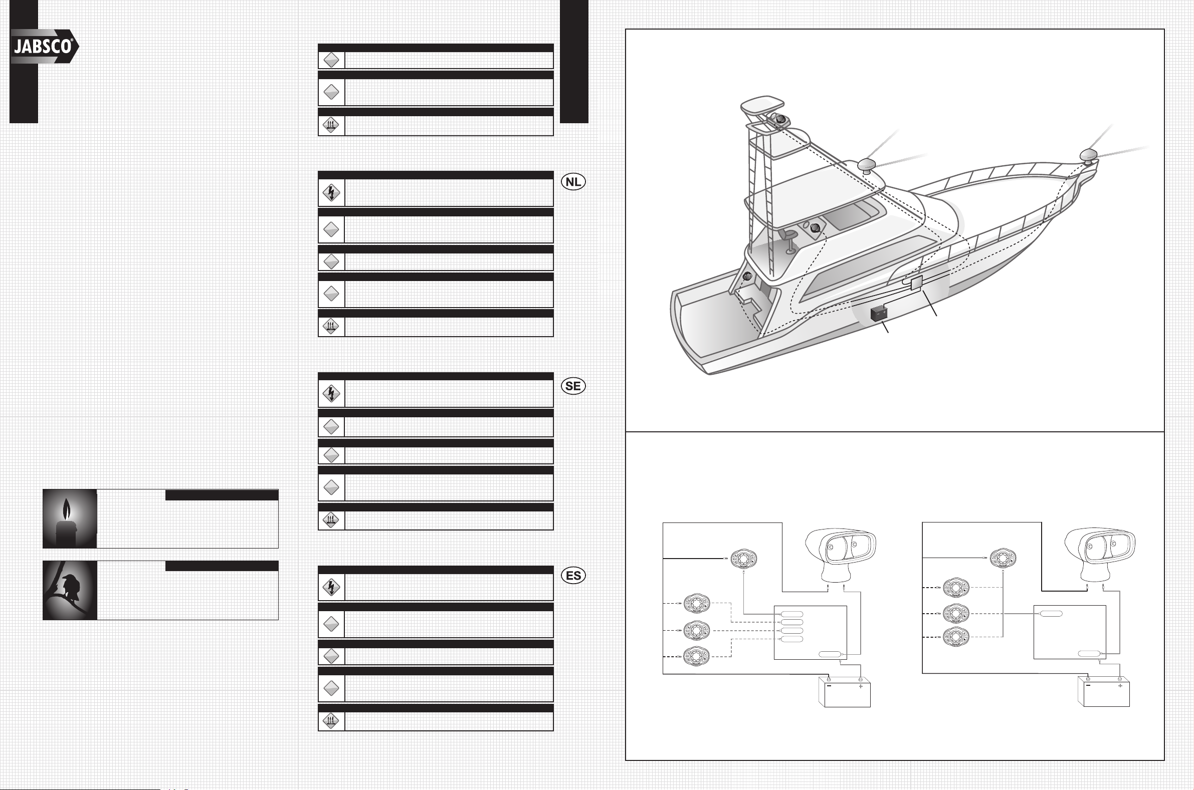
+
–
Black (–)
C
A
B
D
E1
E3
E2
Red (+)
C2
C2
Red (+)
Black (–)
C4
C3
C5
C1
233
+
–
Black (–)
C
A
B
D
E1
E3
E2
Red (+)
C2
C2
Red (+)
Black (–)
C1
233
Electrical Wiring Diagrams
Option 1 Option 2
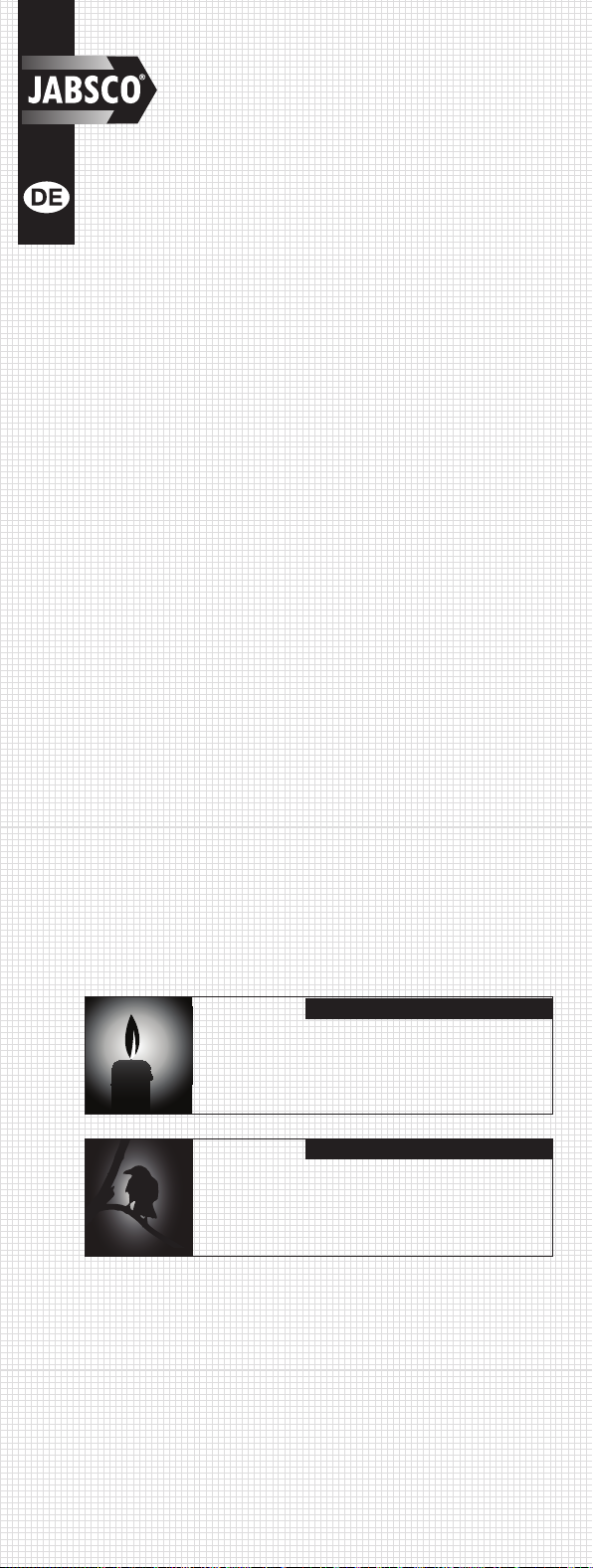
Candlepower
The first standard for the measurement of light consisted of a
spermaceti candle of standard dimensions burning at a certain
rate, giving off light in one direction. This was known as a
standard candle, and its light from any one direction was said to
have an intensity of one candlepower. This is also know as one
candela. A candle emits one candlepower.
LUX
LUX is a unit of measurement of the intensity of light. It is equal
to the illumination of a surface one meter away from a single
candle. The International System unit of illumination, equal to one
lumen per square meter.
Dual Beam Wireless
Remote Control
Searchlight
• Powerful dual beam halogen bulb configuration gives
200,000 candlepower
• Patent protected focus mechanism delivers true Spot/Flood
capability
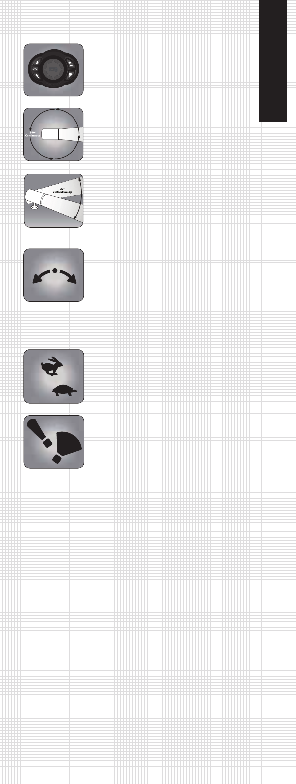
• Wireless searchlight control system allowing up to 4 easy-to-
install control stations
• Infinite motion capabilities due to 8-way touch pad directional
control
• Rugged anodized & painted aluminum housing for total corrosion
resistance
• Continuous rotation capabilities while eliminating slip ring
corrosion
• 27° vertical capabilities uses rugged Delrin™ components and
heavy duty gear motor
• Patent protected sweep feature giving accurate and constant
+/- 10 degree from starting location
• Fast and Slow capabilities for accurate marker identification
• Patent protected easy to install bayonet base with security
locking mechanism.
APPLICATION
A marine searchlight must be capable of performing a range of tasks
from locating buoys to illuminating a narrow channel. The new 233SL
has been designed to offer the best combination of beam spread
(width) and intensity (length), for both shorter and longer range
(work).
The 233SL can also be used on medium to larger motor homes for
illuminating driveways to campsites, road signs and as a back-up
light.
PERFORMANCE DATA
Jabsco quotes performance data in two ways: Candle power & Lux.
Candle power is a useful guide to actual light produced. It does not
however, measure the efficiency of the reflector design to project
light at a target. The most relevant comparison guide is LUX, which
is the measurement of actual light available at a given distance. In
order to to distinguish a reasonable level of detail, a level of one lux
is generally necessary.
200,000
1 LUX (SPOT) @ 1,452 ft. (443 m)
ATTENZIONE
!
Non installare attraverso le superfici dello scafo.
AVVERTENZA
!
La rottura imprevista può causare infortuni, incendio o danno alla proprietà.
Non accendere il proiettore prima che sia completamente installato. Tenere
il prodotto lontano dai bambini.
ATTENZIONE
Rischio di ustioni. Prima di maneggiare il proiettore, attendere che si sia
raffreddato.
DANNO E SMALTIMENTO
• Non usare il proiettore se il vetro esterno è graffiato o rotto.
• Restituire il proiettore rotto alla Xylem in un contenitore chiuso per la valutazione e
riparazione, oppure il possibile smaltimento.
WAARSCHUWING
Volg bij gebruik van het 233SL Zoeklicht altijd de veiligheidsmaatregelen om
het risico op letsel, brand of elektrische schokken te beperken. De nominale
spanning niet overschrijden.
VOORZICHTIG
!
Dit zoeklicht is uitsluitend bestemd voor gebruik aan boord, op een werf en
als werklamp. Het zoeklicht is niet bestemd of ontworpen voor gebruik op de
weg als grootlicht.
VOORZICHTIG
!
Niet door de scheepsromp heen monteren.
WAARSCHUWING
!
Onverwacht breken kan letsel, brand of materiële schade veroorzaken. Zet
het zoeklicht pas aan als het volledig is geïnstalleerd. Buiten het bereik van
kinderen houden.
VOORZICHTIG
Risico op brandwonden. Het zoeklicht eerst laten afkoelen voor aanraking.
BESCHADIGING EN AFVOER
• Gebruik het zoeklicht niet als het buitenste glas krassen of barsten vertoont.
• Retourneer het gebroken zoeklicht in een gesloten verpakking naar Xylem voor
inspectie en reparatie of eventuele afvoer.
VARNING!
Följ alltid säkerhetsföreskrifterna när du använder 233SL-strålkastaren för
att minska risken för personskada, brand eller elektrisk stöt. Överstig inte
märkspänningen.
VAR FÖRSIKTIG!
!
Denna strålkastare är endast avsedd för båt-, terräng- och yrkesbruk. Den
är inte avsedd för användning på vägar och gator som körljus.
VAR FÖRSIKTIG!
!
Montera inte genom skrovet.
VARNING!
!
Oväntad bristning kan orsaka personskada, brand eller egendomsskada.
Slå inte på strålkastaren förrän den är helt installerad. Håll produkten på
avstånd från barn.
VAR FÖRSIKTIG!
Brandfara. Låt strålkastaren svalna före hantering.
SKADA OCH AVYTTRING
• Använd inte strålkastaren om det yttre glaset är repat eller sprucket.
• Returnera en söndrig strålkastare till Xylem för utvärdering och reparation eller möjlig
avyttring.
ADVERTENCIA
A fin de reducir el riesgo de lesiones, incendio o electrocución, cumpla
siempre las precauciones de seguridad cuando use el proyector de
búsqueda 233SL. No exceda el voltaje especificado.
PRECAUCIÓN
!
Este proyector de búsqueda es para uso marino, fuera de las carreteras y
en aplicaciones utilitarias únicamente. No está previsto ni diseñado para
uso en carreteras como luz de conducción.
PRECAUCIÓN
!
No se debe montar el proyector atravesando las superficies del casco.
ADVERTENCIA
!
La rotura accidental puede causar lesiones, incendios o daños a la
propiedad. No encienda el proyector hasta que esté completamente
instalado. Mantenga el producto fuera del alcance de los niños.
PRECAUCIÓN
Riesgo de quemaduras. Deje enfriar el proyector antes de manipularlo.
DAÑOS Y DESECHO
• No use el proyector si el vidrio exterior está rayado o roto.
• Devuelva el proyector roto, en un recipiente cerrado, a Xylem para evaluación,
reparación o posible desecho.
AA*
B
C
D
E1
E2