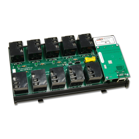
Xytronix Research & Design WebRelay-10 X-WR-10R12-I User manual

WebRelay-10
Title Page
Goes Here

WebRelay-10 Users Manual
Table of Contents
Section 1: Introduction.............................................................................................................................................................. 4
1.1 Features......................................................................................................................................................................... 5
1.2 Applications................................................................................................................................................................... 5
1.3 WebRelay-10 Models Available..................................................................................................................................... 6
1. Connectors & Indicators................................................................................................................................................ 7
1.5 Accessing WebRelay-10................................................................................................................................................ 8
Section 2: Installation and Setup ............................................................................................................................................ 9
2.1 Mounting...................................................................................................................................................................... 10
2.2 Connections................................................................................................................................................................. 11
2.3 Establishing Communications for Setup......................................................................................................................16
2. WebRelay-10 Setup Pages ........................................................................................................................................ 21
Section 3: Operation................................................................................................................................................................ 54
3.1 Browser Operation....................................................................................................................................................... 5
3.2 XML Operation............................................................................................................................................................. 56
3.3 Configuring Events Through GET Requests (WebRelay-10 Plus™ only)...................................................................61
3. Modbus Operation....................................................................................................................................................... 63
3.5 Email Notification......................................................................................................................................................... 78
Appendix A: estoring Factory Default Settings.................................................................................................................. 80
Appendix B: Installing New Firmware.................................................................................................................................... 81
Appendix C: Accessing Web elay-10TM Over the Internet................................................................................................83
Appendix D: Log Files (Web elay-10 Plus™ only)...............................................................................................................87
Appendix E: External Server and emote Services.............................................................................................................90
Appendix F: SNMP equests, Objects and Community Strings.........................................................................................92
Appendix G: BASIC Scripts.................................................................................................................................................... 95
Appendix H: Specifications.................................................................................................................................................. 101
Appendix I: Warranty............................................................................................................................................................. 104
Appendix J: FCC Statement.................................................................................................................................................. 105
Appendix K: Trademark and Copyright Information..........................................................................................................106
Appendix L: Mechanical Information................................................................................................................................... 107
page 2 Xytronix Research & Design, nc.

WebRelay-10 Users Manual
Web elay-10 User Manual evisions
evision Description
2.6 Changed input voltage specification from 10-36VDC to 9-28VDC
Updated power requirements for 9-28VDC operation
Changed relay contact specification from 30amps to 15amps
Moved warranty and trademark information to the appendix
Changed warranty to 5-years
2.7 Clarified relay specifications
Xytronix Research & Design, nc. page 3

Introduction WebRelay-10 Users Manual
Section 1: Introduction
WebRelay-10™ is a robust, 10-relay module with a built-in web server. It can be controlled and/or
monitored over any IP network including private networks, IP-based industrial control networks, and the
Internet. Users can operate WebRelay-10 using a web browser or a custom application. Computers,
PLCs, or automation controllers may control and monitor WebRelay-10 without user intervention. This
works by sending text commands over the network and reading XML status pages from WebRelay-10,
or by using Modbus/TCP protocol.
page 4 Xytronix Research & Design, nc.

WebRelay-10 Users Manual Introduction
1.1 Features
Web elay-10 includes the following features:
- Ten independent 15-Amp Relays (Form C, SPDT).
- Built-in Web server for browser-based setup and control.
- No special software or device drivers required.
- Customizable email alerts.
- XML status and Control Page make communications with custom computer applications simple.
- Can operate as a Modbus/TCP slave.
- On/Off and Pulse modes.
- Advanced functionality through BASIC scripts.
- Wide power supply range (9-28 VDC).
- DIN-Rail Mountable.
- LED relay state indicators.
- ¼ inch tab-connectors.
- UL/CUL listed relays (E197852).
Web elay-10 Plus™ (Model X-W -10 12-IP) also includes the following features:
- Event scheduler with yearly calendar. Schedule up to 100 events.
- Up to eight temperature and/or humidity sensors can be added for environmental monitoring.
- Dry-contact sensors or switches can be connected for local control of relays or for monitoring external
devices.
- Logging: log relay changes, events, Modbus requests, high/low temperatures, input changes,
network traffic, and more.
- Real-time clock, can automatically adjust for daylight savings time, Sync with NTP server.
- System log provides detailed diagnostic information.
- Configure manually or with DHCP.
Note: WebRelay-10 sends out email messages only. Most wireless carriers provide free services to
convert email messages to text messages.
1.2 Applications
WebRelay-10 has many applications. It works very well as a stand-alone device that can be controlled
using a web browser, or as a convenient way to add I/O to a computer. It can be used in industrial
applications to control motors, lights, coils, pumps, valves, etc.
Using the additional features found on WebRelay-10 Plus™, you can monitor temperature and/or
humidity, control multiple relays using an input, schedule reoccurring events, log relay state changes,
and much more.
Xytronix Research & Design, nc. page 5

Introduction WebRelay-10 Users Manual
1.3 Web elay-10 Models Available
WebRelay-10 is currently available in two models. The main differences between each model are listed
below.
X-WR-10R12-I Standard WebRelay-10 with built-in web server, and ten individually controlled
relays.
X-WR-10R12-IP
(WebRelay-10 Plus)
WebRelay-10 Plus™ includes all features of standard model plus
temperature/humidity monitoring (humidity monitoring requires optional humidity
sensor), discrete inputs, real-time clock, event scheduling, capacitor power
backup, and logging.
1.3.1 Optional Accessories (Web elay-10 Plus)
Accessory Description Part Number
Temperature Sensor Digital temperature sensor with 12 inch wire leads.
Note: Leads may be extended
X-DTS-U
Temperature Sensor
(Wall Mount)
Digital temperature sensor housed in vented plastic
enclosure
X-DTS-WM
Temperature/Humidity
Sensor (Wall Mount)
Digital temperature and humidity sensor housed in
vented plastic enclosure.
X-DTHS-WM
page 6 Xytronix Research & Design, nc.

WebRelay-10 Users Manual Introduction
1.4 Connectors & Indicators
Version H (Newest version) – Gnd and Vin+ pin position moved from version 2.3
Version G (Older version)
Xytronix Research & Design, nc. page 7
Figure 1.4a - Connections & Indicators

Introduction WebRelay-10 Users Manual
Module Power Connectors
Two 1/ ” tab connectors located on the circuit board are used to apply power to the module.
Relay Connectors
Each relay has three ¼” tab connectors for common, normally open, and normally closed contacts.
Female mating connectors (not included) are required for connecting user circuits.
Network Connector
The Ethernet connector is located on a small CPU daughter card that is mounted to the main relay
board.
I/O Connector
WebRelay-10 Plus™ includes a 5-position removable terminal connector for discrete inputs and
temperature and/or humidity sensors.
Relay Indicators
Ten green LEDs indicate when each relay is energized. The LEDs are located next to the
corresponding relays. When the relay is energized, the common and normally open contacts are
closed. When the relay is not energized, the common and normally closed contacts are closed.
Module Power Indicator
The green power LED indicator is located on the main relay board in between relays 1 and 6.
Ethernet Indicators
The LINK LED is illuminated green when the module is properly connected to an Ethernet network
and is ready to communicate. Network communications will only occur if this LED is illuminated. The
ACT LED flashes amber when activity is detected on the network.
1.5 Accessing Web elay-10
Standard Access Using a Web Browser
WebRelay-10 has a built-in web server that provides simple web pages that can be accessed directly
using a standard web browser. This allows users to access the unit with NO SPECIAL SOFTWARE
installed on their computer. This is ideal for applications that require a quick, simple solution that does
not need to be accessible to more than a few people. This configuration is simple to setup, simple to
use, and can be accessed from any computer.
Note: Networ routers may need to be configured to allow access from computers outside of the local
networ (see Appendi C: Accessing WebRelay-10TM Over The Internet).
page 8 Xytronix Research & Design, nc.

WebRelay-10 Users Manual Installation and Setup
Section 2: Installation and Setup
Installation consists of mounting WebRelay-10, connecting it to an Ethernet network, providing power,
configuring via a web browser, and wiring relay contacts to the device that will be controlled.
For WebRelay-10 Plus™ models, inputs and sensors can be wired to the device using the 5-position
terminal connector.
Installation Guidelines ( ead Before Installing)
•This unit must be installed by qualified personnel.
•This unit must not be installed in unprotected outdoor locations.
•The WebRelay-10 must installed inside an NRTL certified industrial control panel or similar
NRTL certified fire/electrical enclosure.
•If the WebRelay-10 is used in a manner not specified by Xytronix, the protection provided by the
equipment may be impaired.
•This unit must not be used for medical, life saving purposes, or for any purpose where its failure
could cause serious injury or the loss of life.
•This unit must not be used in any way where its function or failure could cause significant loss or
property damage.
•The relay tab terminals are 1/ ” x .032”. Use UL listed quick-connect connectors suitable for field
connections. Use a suitable crimping tool as specified by the connector manufacturer. Use wire
rated for 75ºC (min) for connections to the relays.
Security Notes
WebRelay-10 does not employ a general purpose computer operating system and does not have
features, such as telnet, FTP, SSH, nor uncontrolled open ports. This means it is unlikely for someone to
‘break in’ to WebRelay-10 and access other devices on your local network. The simplicity of WebRelay-
10 makes it a inherently secure device. Nevertheless, as with any device installed on a network,
appropriate security precautions should be observed.
If WebRelay-10 is installed on the Internet, it is recommended that passwords be enabled for the
Control Page. Passwords should be at least 8 characters in length and use a combination of upper and
lower case letters and numbers. For additional security, a firewall may be used to limit access to
selected IP addresses. Another option may be to set up a Virtual Private Network (VPN) between the
network where WebRelay-10 resides and the client machine (web browser, another, ControlByWeb™
product, etc.).
Final Installation Notes
This ControlByWeb™ product supports connection to 10 Mbps and 100 Mbps networks. Although
100Mbps networks are faster, the amount of data transferred to and from this device is very minimal and
little, if any, performance increase will be gained by setting it to 100 Mbps. There are advantages,
however, to operate this device at 10 Mbps. At 10 Mbps, less power is required, the unit runs cooler,
and the lifetime of the product will be extended.
Any changes to the Ethernet settings will require a removing and re-applying power to WebRelay-10.
Xytronix Research & Design, nc. page 9

Installation and Setup WebRelay-10 Users Manual
2.1 Mounting
WebRelay-10 can be mounted to a standard (35mm by 7.55mm) DIN-Rail. Attach the module to the
DIN-Rail by placing the top hooks on the back of WebRelay-10 to the DIN-Rail and then snapping the
bottom hooks into place. Remove from the DIN-Rail by depressing the latch-release on the mounting
bracket.
See Appendix L: Mechanical Information for additional mechanical details.
page 10 Xytronix Research & Design, nc.
Figure 2.1a - DIN-Rail Mount

WebRelay-10 Users Manual Installation and Setup
2.2 Connections
CAUTION: MAKE SU E POWE IS SHUT OFF BEFO E WI ING!
CAUTION: THIS UNIT SHOULD BE INSTALLED BY A QUALIFIED TECHNICIAN.
MIS-WI ING O MIS CONFIGU ATION COULD CAUSE PE MANENT DAMAGE TO THE
Web elay-10 AND/O THE EQUIPMENT TO WHICH IT IS CONNECTED.
Relay connections are made through the ¼ inch male tab connectors. Mating connectors (¼ inch female
tab connectors) can be purchased at electrical supply stores.
It is recommended that the load (device to be controlled) not be connected to WebRelay-10 until after
WebRelay-10 has been configured and tested. By doing this, wiring and configuration mistakes will not
cause the attached devices to turn on unexpectedly.
IMPORTANT: WIRES SHOULD BE PROPERLY CRIMPED TO THE CONNECTORS, AND
CONNECTORS SHOULD BE PROPERLY ATTACHED TO THE CIRUCIT BOARD OR RELAYS!
2.2.1 Power Supply Connection
WebRelay-10 requires power for its internal logic circuits. Connect a 9-28VDC power supply to the Vin+
and Gnd terminals. Note that a regulated power supply is recommended, such as a wall-mount AC-DC
adapter. Verify that the adapter is rated for the operating current of WebRelay-10 (See Appendix H:
Specifications for current requirements.)
Multiple WebRelay-10 units may be connected to a single power supply by connecting the power supply
input terminals in parallel. The power supply must have a high enough current rating to power all units
connected. (See Appendix H: Specifications for current requirements.)
The power input tab terminals are 1/ ” x .032”. Use UL listed quick-connect connectors suitable for field
connections. Use a suitable crimping tool as specified by the connector manufacturer. Use wire rated for
75ºC (min) for the power connections.
2.2.2 elay Connection
Direct connection to relay contacts is provided through tab connectors located on the top of the relays.
Do not exceed the specified load ratings for relay contacts (see Appendix H: Specifications for load
ratings). The relay tab terminals are 1/ ” x .032”. Use UL listed quick-connect connectors suitable for
field connections. Use a suitable crimping tool as specified by the connector manufacturer. Use wire
rated for 75ºC (min) for connections to the relays.
2.2.3 Network Connection
Connect the Ethernet port to a 10 Base-T or 10/100 Base-T Ethernet connection. This typically connects
to an Ethernet hub, switch, or router. For configuration, WebRelay-10 may be connected directly to the
Ethernet port on a computer using a “crossover” cable. Otherwise, for connection through a hub or
router, a standard “straight-through” cable should be used.
Xytronix Research & Design, nc. page 11

Installation and Setup WebRelay-10 Users Manual
WebRelay-10 can be used on a wireless network by connecting through an Ethernet bridge or a wireless
router. WebRelay-10 is connected directly to the wireless device.
Note: The wireless Ethernet bridge or router must be properly configured for the wireless networ . Refer
to the installation instructions for the wireless device.Terminal Connector (WebRelay-10 Plus™ only)
The removable 5-position terminal connector is used for connecting temperature sensors, humidity
sensors, or discrete inputs. The terminals are described in the table below.
IMPORTANT: MAKE SURE WIRES ARE PROPERLY ATTACHED TO THE TERMINALS AND THAT
THE SCREW TERMINALS ARE TIGHT!
5-pin connector pinout
Pin Description
Data Temperature/Humidity Data. This is the data line
connection for the digital temperature/humidity sensors.
+5V Out This output voltage is used to provide power for the digital
temperature/humidity sensors.
Ground Ground connection for 5VDC output, and Inputs.
Input 1 & 2 Discrete Inputs.
page 12 Xytronix Research & Design, nc.
Figure 2.2a - Network Connection
Figure 2.2b - Wireless Connection

WebRelay-10 Users Manual Installation and Setup
Input Connection (Web elay-10 Plus™ only)
Two discrete inputs can be connected to dry contact sensors or switches. Third party sensors can be
used for monitoring alarm conditions such as door access switches or transducer thresholds. Inputs can
also be used for operator switches and the unit can be configured such that they control the relays.
Connect one terminal of sensor or switch to the input terminal (Input 1 or Input 2). Connect the other
terminal to the ground terminal on WebRelay-10 Plus™. When contacts are closed the input is
connected to ground and the input is considered to be ON. Switch current is less than 2 mA.
Xytronix Research & Design, nc. page 13
Figure 2.2d - In ut Schematic
Figure 2.2c - Connector Pinout

Installation and Setup WebRelay-10 Users Manual
Temperature/Humidity Sensor Connection (Web elay-10 Plus™ only)
Temperature and/or humidity sensors can be used for monitoring environmental conditions. The digital
sensors use a one-wire data bus, which allows up to eight sensors to share the same terminals (+5V,
Ground, Data). Every sensor on the one-wire bus is assigned a unique serial number when it is
manufactured. That number is used to address the device during communication.
The sensors have three wires; the wire color is show in the table below.
Sensor Wire Color Connection
Red Vout
Black Gnd
Blue (or White) Data
Multiple sensors can be connected in two ways, directly connected to the unit (star topology) or “daisy
chained” (linear topology) as shown in Figure 2.2g.
page 14 Xytronix Research & Design, nc.
Figure 2.2e - In ut Connector
Figure 2.2f - Tem erature Sensor

WebRelay-10 Users Manual Installation and Setup
Many factors will determine the maximum length of cable used to connect sensors to WebRelay-10
Plus™. Some of these factors include, but are not limited to, the type of cable used, the number of
sensors, ambient electromagnetic noise, and sensor network topology. Combined cable lengths to all
sensors of 600 ft using Cat 5e cable have been successful. However, due to the uniqueness of
installation environments, results may vary. Please test in the desired environment before permanent
installation.
The following are general recommendations that will maximize sensor runs and minimize problems.
Cat 5 and Cat 5e network cable has proven to be an effective and low-cost solution for long runs. Other
cable types can be used, but cable capacitance may limit the length. Figure 2.2h shows the
recommended connection using Cat 5 network cable.
A linear (daisy chain) rather than a star (direct connection) topology will minimize signal reflections.
Appropriate strain relief should be used at the WebRelay-10 and other connections that may be
subjected to vibration, movement, or repeated handling.
The 1-wire bus is "single-ended" and has no intrinsic noise protection. It is susceptible to interference if
the cable is routed near power lines, fluorescent fixtures, motors or other noise sources. Keep the cable
wiring short and avoid routing it near other electrical equipment.
Protect any electrical connections with appropriate weather shielding.
Due to the broad range of applications and environments were the WebRelay-10 may be employed,
installation success on long sensor runs may vary significantly.
Xytronix Research & Design, nc. page 15
Figure 2.2g - Direct Connection (Star) and Daisy Chain Connection(Linear)
Figure 2.2h - Recommended connection using Cat 5 cable

Installation and Setup WebRelay-10 Users Manual
2.3 Establishing Communications for Setup
In order to configure WebRelay-10 with the web browser interface, WebRelay-10 must be connected to
an Ethernet computer network. This can be done by one of two methods:
Method 1 – Assign a temporary IP address of WebRelay-10 to work on an existing network.
-or-
Method 2 – Temporarily change the IP address of a connected computer to the match the default IP
address used by WebRelay-10.
Note: If multiple ControlByWeb™ products are used on the same networ , install one at a time and set
the IP address of each unit before connecting the next unit to the networ . This avoids having multiple
devices being installed on the networ with the same factory default IP address at the same time. If this
approach is used, be sure to clear the arp cache after disconnecting each unit (arp -d).
2.3.1 Method 1: Assign a Temporary IP address to Web elay-10
This option is used to TEMPORARILY assign an IP address to WebRelay-10 without the need to change
the IP address of the configuration computer. WebRelay-10 will use this IP address as long as power is
maintained. Once power is lost, WebRelay-10 will use the IP address assigned in the setup page and
not the temporary address assigned here.
Make sure that WebRelay-10 and the configuration computer are connected to the same network.
This will not work through routers or gateways.
Microsoft Windows Instructions
1. Open a Command Prompt (select START, then RUN, then type “cmd”).
Note: For Vista, the Command Prompt should be run as administrator (select Start, then type “cmd”
and right clic on “cmd” and select “Run as administrator”).
2. Type:
arp -s {new IP address} {serial number of WebRelay-10 }
Note: IP address format is xxx.xxx.xxx.xxx. The serial number can be found on a label on the
module board. The format is ss-ss-ss-ss-ss-ss.
For example, to set WebRelay-10 (with serial number 00-0C-C8-01-00-01 ) to 10.10.10. 0 the
following command would be used:
arp -s 10.10.10.40 00-0c-c8-01-00-01
3. Next, type:
ping -l 10 {new IP address}
For example, if the new IP address is 10.10.10. 0, the following command would be used:
ping -l 10 10.10.10.40
4. Proceed with WebRelay-10 setup in section 2. .
Once setup is complete, it may be necessary to clear the 'arp' cache to configure additional
WebRelays. This is necessary because each unit has the same default IP address, but a different
unit serial number (MAC address). Clearing the arp table can be done by typing arp -d in the
command prompt window.
Linux/Unix Instructions
1. Open a terminal and change to root user (su -, then enter root password).
2. Type:
page 16 Xytronix Research & Design, nc.

WebRelay-10 Users Manual Installation and Setup
arp -s {new IP address} {serial number of WebRelay-10 }
Note: IP address format is xxx.xxx.xxx.xxx. The serial number can be found on a label on the
module board. The format is ss:ss:ss:ss:ss:ss.
For example, to set WebRelay-10 (with serial number 00-0C-C8-01-00-01 ) to 10.10.10. 0 the
following command would be used:
arp -s 10.10.10.40 00:0c:c8:01:00:01
3. Next, type:
ping -s 10 {new IP address}
For example, if the new IP address is 10.10.10. 0, the following command would be used:
ping -s 10 10.10.10.40
4. Proceed with WebRelay-10 setup in section 2. .
Once setup is complete, it may be necessary to clear the 'arp' cache to configure additional
WebRelays. This is necessary because each unit has the same default IP address, but a different
unit serial number (MAC address). Clearing the arp table can be done by typing sudo arp -d -a
in the command prompt window.
Mac OS X Instructions
1. Open a terminal.
Note: The terminal is in the “Utilities” directory, which is in the “Applications” directory.
2. Type:
sudo arp -s {new IP address} {serial number of WebRelay-10 }
Administrator password may be required.
Note: IP address format is xxx.xxx.xxx.xxx. The serial number can be found on the label on the
module board. The format is ss:ss:ss:ss:ss:ss.
For example, to set a WebRelay-10 (with serial number 00-0C-C8-01-00-01 ) to 10.10.10. 0 the
following command would be used:
sudo arp -s 10.10.10.40 00:0c:c8:01:00:01
3. Next, type:
ping -s 10 {new IP address}
For example, if the new IP address is 10.10.10. 0, the following command would be used:
ping -s 10 10.10.10.40
4. Proceed with WebRelay-10 setup in section 2. .
Once setup is complete, it may be necessary to clear the 'arp' cache to configure additional WebRelays.
This is necessary because each unit has the same default IP address, but a different unit serial number
(MAC address). Clearing the arp table can be done by typing sudo arp -d -a in the command prompt
window.
Xytronix Research & Design, nc. page 17

Installation and Setup WebRelay-10 Users Manual
2.3.2 Method 2: Assign a Temporary IP Address to Configuration Computer
If the first option above is not used, you can use this option to communicate with WebRelay-10. By
default, WebRelay-10 comes from the factory with an IP address of 192.168.1.2. Communications with
WebRelay-10 may be established by assigning an IP address to the configuration computer that is on
the same network as WebRelay-10 (for example, the configuration computer could be assigned to
192.168.1.50)
The following example is for those running the Windows operating system:
1. Windows XP – Open the control panel by clicking on the start menu
and then on Control Panel.
Windows Vista/7 – Select the Windows Icon (Start Menu) and enter
ncpa.cpl into the search bar and press Enter (Figure 2.3a).
Note: The control panel
shown (Figure 2.3b) is in
“Classic View.” If the
control panel is in
“Category View,” select
the “Classic View” option
before proceeding.
2. Double click on
the icon labeled
Network
Connections. The
Network
Connections
window will open
(Figure 2.3c).
page 18 Xytronix Research & Design, nc.
Figure 2.3b- Control Panel
Figure 2.3a- Vista/7 Start
Menu
Figure 2.3c- Network Connection

WebRelay-10 Users Manual Installation and Setup
3. Right click on the icon labeled Local Area
Connection. In the menu that follows, select the
option at the bottom of the menu labeled Properties.
The Local Area Connection Properties window will
appear (Figure 2.3c).
Xytronix Research & Design, nc. page 19
Figure 2.3d- Local Area Connection

Installation and Setup WebRelay-10 Users Manual
4. In the Local Area Connection Properties window in
the Connection Uses box, scroll down and
highlight “Internet Protocol (TCP/IP).” Click the
button labeled “Properties.” The “Internet Protocol
(TCP/IP)” Properties menu appears (Figure 2.3e).
5. Select the radio button labeled "Use the following
IP address" and type in the IP address:
19 .168.1.50
6. Type in the subnet mask:
55. 55. 55.0
No need to change the default gateway field. Click
OK to accept the new settings.
Note: If “Use the following IP address” is already
selected, the computer has been set up with a
static IP address. Record these values so that the
computer can be restored once the IP address of
WebRelay-10 is successfully changed.
7. Open the setup pages as described in section 2. .
If the setup pages are not accessible, verify that
WebRelay-10 is powered on and that the LINK
light is illuminated. Check all network connections and settings.
Another way to check communications is to ping WebRelay-10 (from the command prompt by typing
ping {WebRelay-10 IP address} ).
page 20 Xytronix Research & Design, nc.
Figure 2.3e- TCP/IP Pro erties
This manual suits for next models
1
Table of contents
Other Xytronix Research & Design Control Unit manuals