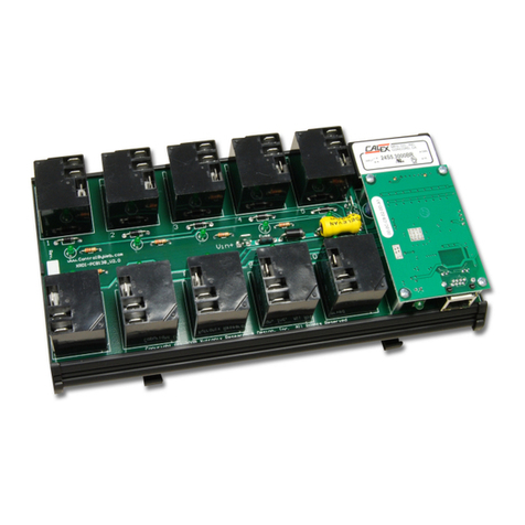
Xytronix Research & Design ControlByWeb X317 User manual


X-317™ Users Manual
X-317 User Manual Revisions
Revision Description
1.0 Initial release
1.1 Minor grammatical cleanup
1.2 Changed Modbus addressing
Page 2 Xytronix Research & Design, Inc.

X-317™ Users Manual
Table of Contents
Section 1: Introduction 6
1 1 Features 7
1.1.1 X-317™ eatures:.............................................................................................................................. 7
1.1.2 Digital to Analog Converter................................................................................................................. 7
1 2 Connectors & Indicators 8
1 3 Accessing the X-317 9
1 4 Part Numbers and Accessories 9
Section 2: Installation and Connections 10
2 1 Installation Guidelines 10
2 2 Security Notes 10
2 3 Connection Speed 10
2 4 Mounting 11
2 5 Making Connections 11
2.5.1 Power Supply Connections............................................................................................................... 12
2.5.2 Analog Output Connections.............................................................................................................. 13
2.5.3 Network Connection......................................................................................................................... 14
2 6 Establishing Communications for Setup 15
2.6.1 Method 1: Assign a Temporary IP Address to Configuration Computer ...........................................15
2.6.2 Method 2: Assign a Temporary IP address to the X-317................................................................... 19
Microsoft Windows Instructions.......................................................................................................19
inux/Unix Instructions....................................................................................................................19
Mac OS X Instructions..................................................................................................................... 20
Section 3: Example Applications 21
Process Control................................................................................................................................ 21
Manual Control................................................................................................................................ 22
Section 4: Configuration and Setup 23
4 1 X-317 Setup Pages 23
4.1.1 Main Tab........................................................................................................................................... 23
4.1.2 Network Tab...................................................................................................................................... 24
4.1.3 Advanced Network Tab..................................................................................................................... 26
4.1.4 Password Tab................................................................................................................................... 29
4.1.5 Analog Outputs Tab.......................................................................................................................... 30
4.1.6 Script Tab ......................................................................................................................................... 33
4.1.7 Control Page Setup Tab.................................................................................................................... 36
Section 5: Operation 38
5 1 Browser Operation 38
5 2 XML Operation 40
5.2.1 XML Monitoring................................................................................................................................. 40
5.2.2 XML Control...................................................................................................................................... 41
5.2.3 XML Password.................................................................................................................................. 41
5.2.4 XML Diagnostics............................................................................................................................... 42
5 3 Modbus Operation 43
5.3.1 X-317 unction Code Summary........................................................................................................ 43
Xytronix Research & Design, Inc. Page 3

X-317™ Users Manual
5.3.2 PLC Device Addressing.................................................................................................................... 44
5.3.3 X-317 Modbus Address Table........................................................................................................... 45
5.3.4 Read Holding Registers – Modbus unction Code 03 (0x03)........................................................... 46
5.3.4.1 Request..................................................................................................................................... 46
5.3.4.2 Response.................................................................................................................................. 46
5.3.4.3 Errors......................................................................................................................................... 47
5.3.5 Write Multiple Registers (Modbus unction Code 16 (0x10))...........................................................48
5.3.5.1 Request..................................................................................................................................... 48
5.3.5.2 Response.................................................................................................................................. 48
5.3.5.3 Errors......................................................................................................................................... 49
Appendix A: Restoring Factory Default Settings 50
Appendix B: Installing New Firmware 51
Appendix C: Accessing the X-317 Over the Internet 53
Appendix D: BASIC Scripts 57
ine Format..................................................................................................................57
ET.............................................................................................................................. 58
IF THEN, E SE, END IF ............................................................................................58
FOR TO, NEXT........................................................................................................... 58
DO WHI E, OOP......................................................................................................58
END ............................................................................................................................ 58
CA .......................................................................................................................... 58
SUB, END SUB........................................................................................................... 58
REM or ' ...................................................................................................................... 59
PRINT ......................................................................................................................... 59
Timer Variables............................................................................................................ 59
Analog Output Variables.............................................................................................. 59
Appendix E: External Server and Remote Services 61
Appendix F: Specifications 63
Power Requirements.................................................................................................... 63
10 Mbps Network Speed.............................................................................................. 63
100 Mbps Network Speed............................................................................................ 63
Analog Outputs............................................................................................................ 63
Connector .................................................................................................................... 63
ED Indicators............................................................................................................. 64
Network....................................................................................................................... 64
Memory........................................................................................................................ 64
Communications.......................................................................................................... 64
Password Settings.........................................................................................................64
Environmental.............................................................................................................. 64
Mechanical................................................................................................................... 64
Electromagnetic Compliance........................................................................................64
Appendix G: Trademark and Copyright Information 65
Appendix H: Warranty 66
Page 4 Xytronix Research & Design, Inc.

X-317™ Users Manual
imitation..................................................................................................................... 66
Appendix I: FCC Statement 67
Warning........................................................................................................................ 67
Notice........................................................................................................................... 67
Section 6: J: Mechanical Dimensions 68
Xytronix Research & Design, Inc. Page 5

Introduction X-317™ Users Manual
Section 1: Introduction
The X-317™ is a web-enabled analog output module with five output channels. It combines many of the
features found on other ControlByWeb products and adds new capabilities to the product line. Each
channel can be programmed to output a voltage or current. The analog outputs are similar to that of a
Programmable Logic Controller (PLC). However, unlike a PLC, the X-317 is designed for web-based
applications from the ground up. No add-on software or hardware is required. The X-317 can be fully
configured, programmed and tested using its built-in web server. The web setup pages are intuitive and
easy to use and do not require special programming skills.
The X-317 can be used as a stand-alone device. or example, you could set the speed of conveyor or
the position of a HVAC damper by accessing the X-317's internal web page. The X-317 can also
operate as a peripheral for other devices such as a programmable logic controller (PLC) or the X-
600M™.
The X-317 has five precision 16-bit digital to analog converters (DACs). Each channel can be
programmed for 0-5V, 0-10V, ±5V, ±10V, 4-20mA ranges. The voltage and current outputs for each
channel are on a single connector terminal, thus reducing the number of connecter terminals from three
to two.
Most industrial analog applications require isolation between the power supply and analog outputs. The
X-317 has a built in DC-DC converter for providing isolated power to the outputs. No external isolated
back plane power is needed.
The built-in web setup pages allow the name and settings for each channel to be configured. You can
configure the range of a setting to be in engineering units. or example, an input value of 0 to 100% can
be scaled and processed for an output range of 4 to 20mA to control a damper motor.
As with other ControlByWeb products, the X-317 supports a number of Ethernet protocols with it's built-
in server, including HTTP, Modbus/TCP, and XML.
Page 6 Xytronix Research & Design, Inc.

X-317™ Users Manual Introduction
1 1 Features
1 1 1 X-317™ Features:
• ive separate analog output channels
• 0-5V, 0-10V, ±5V, ±10V, 4-20mA output ranges
• Outputs are software configured, independently programmable and scalable
• Built in isolated DC-DC converter
• Wide power supply range (9-28VDC)
• No special software or device drivers required
• Built-in password protected Web server for browser-based setup and control.
• Built-in web page for setting the outputs
• XML and Modbus/TCP communications
• Static or DHCP IP address configuration
• Advanced functionality through BASIC scripts
• DIN-Rail Mountable.
• LED alarm indicators.
• Removable connector for wiring connections
1 1 2 Digital to Analog Converter
The X-317 accepts output settings in familiar engineering units such as V, M, t, KPH, %. Internally
the X-317 automatically scales the output settings before setting the digital to analog converter. This
allows the user to control the output device using familiar and descriptive engineering units.
The internal calculations are made with a linear slope and offset equation (Y=mX+b). With the
default settings, the input and output have a 1 to 1 relationship. or example, with the default
settings, setting the output to 2.0 will result in the analog output being 2.0Volts. When the X-317 is
controlled via ModBus/TCP from a PLC or other device it may be convenient to leave the default
settings undisturbed so that no data scaling is done in the X-317 and any math or other calculations
are done in the PLC or controlling device.
If you wish the X-317 to scale and process the output settings, you can access the Analog Outputs
tab in the Setup menu to change the output settings. or example, you may wish to control a
damper motor and have the display and settings with values of 0 to 100%. When properly
configured, the X-317 will scale a setting of 0% to generate a 4.0mA output, and a setting of 100% to
generate a 20.0mA output.
Xytronix Research & Design, Inc. Page 7

Introduction X-317™ Users Manual
1 2 Connectors & Indicators
I/O Connector
The 12-pin terminal connector is used to provide power to the module and connect the Analog
Outputs.
Network Connector
The Ethernet connector is a standard, 8-position modular receptacle.
Module Power Indicator
The green Power LED indicator is illuminated whenever the module is powered.
I/O Indicators
The four, yellow LEDs indicate the output alarms.
Alarm Condition Yellow LED's
Power Up All four yellow LEDs are momentarily illuminated
All four yellow LEDs remain illuminated if any internal errors are detected
Current Mode Open circuit or compliance voltage violation (current source is saturated)
Over Temperature Die temperature is over +142°C
Page 8 Xytronix Research & Design, Inc.
Connections & Indicators

X-317™ Users Manual Introduction
Ethernet Indicators
The green LINK LED is illuminated when the module is properly connected to an Ethernet network
and is ready to communicate. Network communications will only occur if this LED is illuminated. The
ACT LED flashes amber when activity is detected on the network.
1 3 Accessing the X-317
Standard Access Using a Web Browser
The X-317™ has a built-in web server that provides simple web pages that can be accessed directly
using a standard web browser. This allows users to access the unit with NO SPECIAL SO TWARE
installed on their computer. This is ideal for applications that require a quick, simple solution that does
not need to be accessible to more than a few people. This configuration is simple to setup, simple to
use, and can be accessed from any computer.
Note: Network routers may need to be configured to allow access from computers outside of the local
network (see Appendix C: Accessing the X- 17 Over The Internet).
1 4 Part Numbers and Accessories
Device Description Part Number
X-317 Analog Output Module X-317
Spare Connector 12-position, screw terminal connector X-1803675
Xytronix Research & Design, Inc. Page 9

Installation and Connections X-317™ Users Manual
Section 2: Installation and Connections
Installation consists of mounting the X-317, connecting it to an Ethernet network, providing power, wiring
the analog outputs, and configuring via a web browser.
2 1 Installation Guidelines
•This unit must be installed by qualified personnel. In the case of line-voltage connections, a
licensed electrician should be employed.
•This unit must not be installed in unprotected outdoor locations.
•This unit must not be used for medical, life saving purposes, or for any purpose where its failure
could cause serious injury or the loss of life.
•This unit must not be used in any way where its function or failure could cause significant loss or
property damage
•Do not use to directly control motors or other actuators not equipped with limit switches or other
safeguards to protect from equipment or wiring failures.
2 2 Security Notes
The X-317 does not employ a general purpose computer operating system and does not have features
such as telnet, TP, SSH, nor uncontrolled open ports. This means it is unlikely for someone to ‘break in’
to the X-317 and access other devices on your local network. The simplicity of the X-317 makes it an
inherently secure device. Nevertheless, as with any device installed on a network, appropriate security
precautions should be observed.
If the X-317 is installed on the Internet, it is recommended that passwords be enabled for the Control
Page. Passwords should be at least 8 characters in length and use a combination of upper and lower
case letters and numbers. or additional security, a firewall may be used to limit access to selected IP
addresses. Another option may be to set up a Virtual Private Network (VPN) between the network where
the X-317 resides and the client machine (web browser, another, ControlByWeb™ product, etc.).
2 3 Connection Speed
This ControlByWeb™ product supports connection to 10 Mbps and 100 Mbps networks. Although
100Mbps networks are faster, the amount of data transferred to and from this device is very minimal and
little, if any, performance increase will be gained by setting it to 100 Mbps. There are advantages,
however, to operate this device at 10 Mbps. At 10 Mbps, less power is required, the unit runs cooler,
and the lifetime of the product will be extended.
Any changes to the Ethernet settings will require removing and re-applying power to the X-317.
Page 10 Xytronix Research & Design, Inc.

X-317™ Users Manual Installation and Connections
2 4 Mounting
The X-317 can be mounted to a standard (35mm by 7.55mm) DIN-Rail. The X-317 should be located in
a clean, dry location where it is protected from the elements. Ventilation is recommended for installations
where ambient air temperatures are expected to be high. See Appendix J: Mechanical nformation for
additional mechanical details.
Attach the X-317 to the DIN-Rail by hooking the top hook on the back of the enclosure to the DIN-Rail
and then snap the bottom hook into place. To remove the X-317 from the DIN-Rail, use a flat-head
screwdriver. Insert the screw driver into the notch in the release tab and pry against the enclosure to
release the bottom hook.
2 5 Making Connections
A removable terminal connector is provided for the wiring connections. The correct wiring procedure is
as follows:
1. Make sure power is turned off.
2. Remove the terminal connector from the X-317 and make wiring connections to the terminals.
This technique avoids stressing the internal components while torquing the screws.
3. Reconnect the terminal connector.
4. Apply power.
Xytronix Research & Design, Inc. Page 11

Installation and Connections X-317™ Users Manual
●Make sure wires are properly attached to the terminals and that the terminals are tight!
●Do not route signal cables in the same conduit or raceway with AC power lines feeding motors,
solenoids or other electrically noisy loads. Long cable runs are susceptible to EMI and interference,
keep cable runs as short as possible
●It is recommended that the load (device to be controlled) not be connected to the X-317™ until after
the X-317™ has been configured and tested. By doing this, wiring and configuration mistakes will not
cause the load device to turn on unexpectedly.
12-pin Connector
Pin Description
Vin+ Power Supply +VDC +9 to 28 VDC
DO NOT EXCEED MAXIMUM POWER SUPPLY VOLTAGE.
Vin- VDC- (Ground) power supply input.
Com Analog Ground: Common ground for analog outputs
(Isolated from Vin-)
Aout5 Analog Output 5, 0-5V, 0-10V, ±5V, ±10V, 4-20mA
Com Analog Ground: Common ground for analog outputs
(Isolated from Vin-)
Aout4 Analog Output 4, 0-5V, 0-10V, ±5V, ±10V, 4-20mA
Com Analog Ground: Common ground for analog outputs
(Isolated from Vin-)
Aout3 Analog Output 3, 0-5V, 0-10V, ±5V, ±10V, 4-20mA
Com Analog Ground: Common ground for analog outputs
(Isolated from Vin-)
Aout2 Analog Output 2, 0-5V, 0-10V, ±5V, ±10V, 4-20mA
Com Analog Ground: Common ground for analog outputs
(Isolated from Vin-)
Aout1 Analog Output 1, 0-5V, 0-10V, ±5V, ±10V, 4-20mA
2 5 1 Power Supply Connections
The X-317™ requires power for its internal logic circuits. Connect a 9-28 VDC power supply to the Vin+
and Vin- terminals. Note that a regulated power supply is recommended, such as a wall-mount AC-DC
adapter. Verify that the adapter is rated for the operating current of the X-317 (See Appendix F:
Specifications for current requirements.) Multiple X-317 units may be connected to a single power
supply by connecting the power supply input terminals in parallel. The power supply must have a high
enough current rating to power all units connected.
Page 12 Xytronix Research & Design, Inc.

X-317™ Users Manual Installation and Connections
2 5 2 Analog Output Connections
The analog outputs can be individually programmed to function as 0-5V, 0-10V, ±5V, ±10V, 4-20mA
outputs.
Voltage Output Connections
Many variable frequency drives (V D), servos and other actuators are controlled by a variable voltage.
To use these devices the Aout and Com outputs are connected directly to the device to be controlled. A
connection must be made to the Com terminal. Internally the Vin- and Com pins are isolated by the DC-
DC converter. The maximum output current for voltage outputs is 10mA per channel. The five Com pins
are internally connected together.
Current Output connections
Some actuators are designed to respond to a change of DC current instead of the voltage levels. To use
these devices the Aout and Com outputs are connected directly to the device to be controlled. Power for
the current loop is provided by the X-317. The X-317 employs an internal current source for controlling
the output current. The current source saturates at 11.5V. As such the resistance of your output current
loop must not be more than 575 ohms (575ohm x 0.02A = 11.5V). This includes the input resistance of
the actuator and any wiring in the current loop. If the current loop is open or the loop resistance is too
high the respective yellow fault LED will be illuminated and the web page display will show the output
value as xx.xx.
Xytronix Research & Design, Inc. Page 13

Installation and Connections X-317™ Users Manual
2 5 3 Network Connection
Connect the Ethernet port to a 10 Base-T or 10/100 Base-T Ethernet connection. This typically connects
to an Ethernet hub, switch, or router. or configuration, the X-317 may be connected directly to the
Ethernet port on a computer using a “crossover” cable. Otherwise, for connection through a hub or
router, a standard “straight-through” cable should be used.
The X-317 can be used on a wireless network by connecting through an Ethernet bridge or a wireless
router.
Note: The wireless Ethernet bridge or router must be properly configured for the wireless network. Refer
to the installation instructions for the wireless device.
Page 14 Xytronix Research & Design, Inc.
Wireless Connection
Network Connection

X-317™ Users Manual Installation and Connections
2 6 Establishing Communications for Setup
In order to configure the X-317 with the web browser interface, the X-317 must be connected to an
Ethernet computer network. This can be done by one of two methods:
Method 1– Temporarily change the IP address of a connected computer to the match the default IP
address used by the X-317.
-or-
Method 2 – Assign a temporary IP address to the X-317 to work on an existing network.
Note: f multiple ControlByWeb™ products are used on the same network, install one at a time and set
the P address of each unit before connecting the next unit to the network. This avoids having multiple
devices being installed on the network with the same factory default P address at the same time. f this
approach is used, be sure to clear the arp cache after disconnecting each unit (arp -d).
2 6 1 Method 1: Assign a Temporary IP Address to Configuration Computer
By default, the X-317 comes from the factory with an IP address of 192.168.1.2. Communication with the
X-317 may be established by assigning an IP address to the configuration computer so that it is on the
same network as the X-317 (for example, the configuration computer could be assigned to
192.168.1.50)
The following example is for those running the Windows-8 operating system:
1. Apply Power, wait 15 seconds for the X-317 to become operational, and then connect the Ethernet
cable.
2. Open the Windows 8 start screen.
3. Type “Control Panel” and press enter (the search box opens automatically when you begin typing).
Xytronix Research & Design, Inc. Page 15

Installation and Connections X-317™ Users Manual
4. Select View network status and tasks.
5. Select Change adapter settings
Page 16 Xytronix Research & Design, Inc.

X-317™ Users Manual Installation and Connections
6. Your machine may have more than one Internet connection shown. Right-click on the adapter for
your connection to the internet. A drop down box will appear, choose Properties to view/edit the
settings for this internet connection.
7. Select Internet Protocol Version 4 (TCP/IPV4) and then click the Properties button.
Xytronix Research & Design, Inc. Page 17

Installation and Connections X-317™ Users Manual
8. If “Use the following IP address” is already selected, the computer has been setup with a static IP
address. Record these values so that the current IP address of the computer can be restored once the IP
address of the X-317 has been successfully changed.
Select the radio button labeled "Use the following IP address" and type in the IP address:
192.168.1.50
Type in the subnet mask:
255.255.255.0
No need to change the default gateway field. Click OK to accept the new settings.
9. Open the setup pages by entering the following URL in the address bar of a web browser:
http://{ipaddress}/setup.html
( or example: http://192.168.1.2/setup.html)
If the setup pages are not accessible, verify that the X-317 is powered on and that the LINK light is
illuminated. Check all network connections and settings.
Another way to check communications is to ping the X-317 from the command prompt by typing:
ping [ipaddress] (e.g. ping 192.168.1.2)
Page 18 Xytronix Research & Design, Inc.

X-317™ Users Manual Installation and Connections
2 6 2 Method 2: Assign a Temporary IP address to the X-317
This option (arping) is used to TEMPORARILY assign an IP address to the X-317 without the need to
change the IP address of the configuration computer. The X-317 will use this IP address as long as
power is maintained. Once power is lost, the X-317 will use the IP address assigned in the setup page
and not the temporary address assigned here. Make sure that the X-317 and the configuration computer
are connected to the same network. Since ARP is non-routable, this will not work through routers or
gateways.
Microsoft Windows Instructions
1. Open a Command Prompt (select START, then RUN, then type “cmd”).
Note: For Vista, 7, 8, and 8.1, the Command Prompt should be run as administrator (select
Start, then type “cmd” and right click on “cmd” and select “Run as administrator”).
2. Type:
arp -s {new P address} {serial number of the X-317 }
Note: P address format is xxx.xxx.xxx.xxx. The serial number can be found on a label on the
module board. The format is ss-ss-ss-ss-ss-ss.
or example, to set the X-317 (with serial number 00-0C-C8-01-00-01 ) to 10.10.10.40 the
following command would be used:
arp -s 10.10.10.40 00-0c-c8-01-00-01
3. Next, type:
ping -l 102 {new P address}
or example, if the new IP address is 10.10.10.40, the following command would be used:
ping -l 102 10.10.10.40
4. Proceed with the X-317 setup in section 4.
Once setup is complete, it may be necessary to clear the 'arp' cache to configure additional
devices. This is necessary because each unit has the same default IP address, but a different
unit serial number (MAC address). Clearing the arp table can be done by typing arp -d in the
command prompt window.
Linux/Unix Instructions
1. Open a terminal and change to root user (su -, then enter root password).
2. Type:
arp -s {new P address} {serial number of the X-317 }
Note: P address format is xxx.xxx.xxx.xxx. The serial number can be found on a label on the
module board. The format is ss:ss:ss:ss:ss:ss.
or example, to set the X-317 (with serial number 00-0C-C8-01-00-01) to 10.10.10.40 the following
command would be used:
arp -s 10.10.10.40 00:0c:c8:01:00:01
3. Next, type:
ping -s 102 {new P address}
or example, if the new IP address is 10.10.10.40, the following command would be used:
ping -s 102 10.10.10.40
Xytronix Research & Design, Inc. Page 19

Installation and Connections X-317™ Users Manual
4. Proceed with the X-317 setup in section 4.
Once setup is complete, it may be necessary to clear the 'arp' cache to configure additional devices.
This is necessary because each unit has the same default IP address, but a different unit serial
number (MAC address). Clearing the arp table can be done by typing sudo arp -d -a in the
command prompt window.
Mac OS X Instructions
1. Open a terminal.
Note: The terminal is in the “Utilities” directory, which is in the “Applications” directory.
2. Type:
sudo arp -s {new P address} {serial number of the X-317 }
Administrator password may be required.
Note: P address format is xxx.xxx.xxx.xxx. The serial number can be found on the label on the
module board. The format is ss:ss:ss:ss:ss:ss.
or example, to set the X-317 (with serial number 00-0C-C8-01-00-01 ) to 10.10.10.40 the following
command would be used:
sudo arp -s 10.10.10.40 00:0c:c8:01:00:01
3. Next, type:
ping -s 102 {new P address}
or example, if the new IP address is 10.10.10.40, the following command would be used:
ping -s 102 10.10.10.40
4. Proceed with the X-317 setup in section 4.
Once setup is complete, it may be necessary to clear the 'arp' cache to configure additional devices. This
is necessary because each unit has the same default IP address, but a different unit serial number (MAC
address). Clearing the arp table can be done by typing sudo arp -d -a in the command prompt
window.
Page 20 Xytronix Research & Design, Inc.
Table of contents
Other Xytronix Research & Design Control Unit manuals