Blue Technix Argos3D-P320 Instructions for use

Argos3D-P320
Hardware User Manual
Version 0.4

© Bluetechnix 2015
Bluetechnix
Waidhausenstraße 3/19
A-1140 Vienna
AUSTRIA
www.bluetechnix.com
Argos3D-P320 –Hardware User Manual
Document No.: 900-308 / A
Publication date: August 31, 2015
Subject to change without notice. Errors excepted.
This document is protected by copyright. All rights reserved. No part of this document may be reproduced or
transmitted for any purpose in any form or by any means, electronically or mechanically, without expressly
written permission by Bluetechnix GmbH.
Windows is a registered trademark of Microsoft.

© Bluetechnix 2015
Table of Contents
1General Information.......................................................................................................................... 6
1.1 Symbols Used ........................................................................................................................... 6
1.2 Certification ............................................................................................................................... 7
2Overview........................................................................................................................................... 8
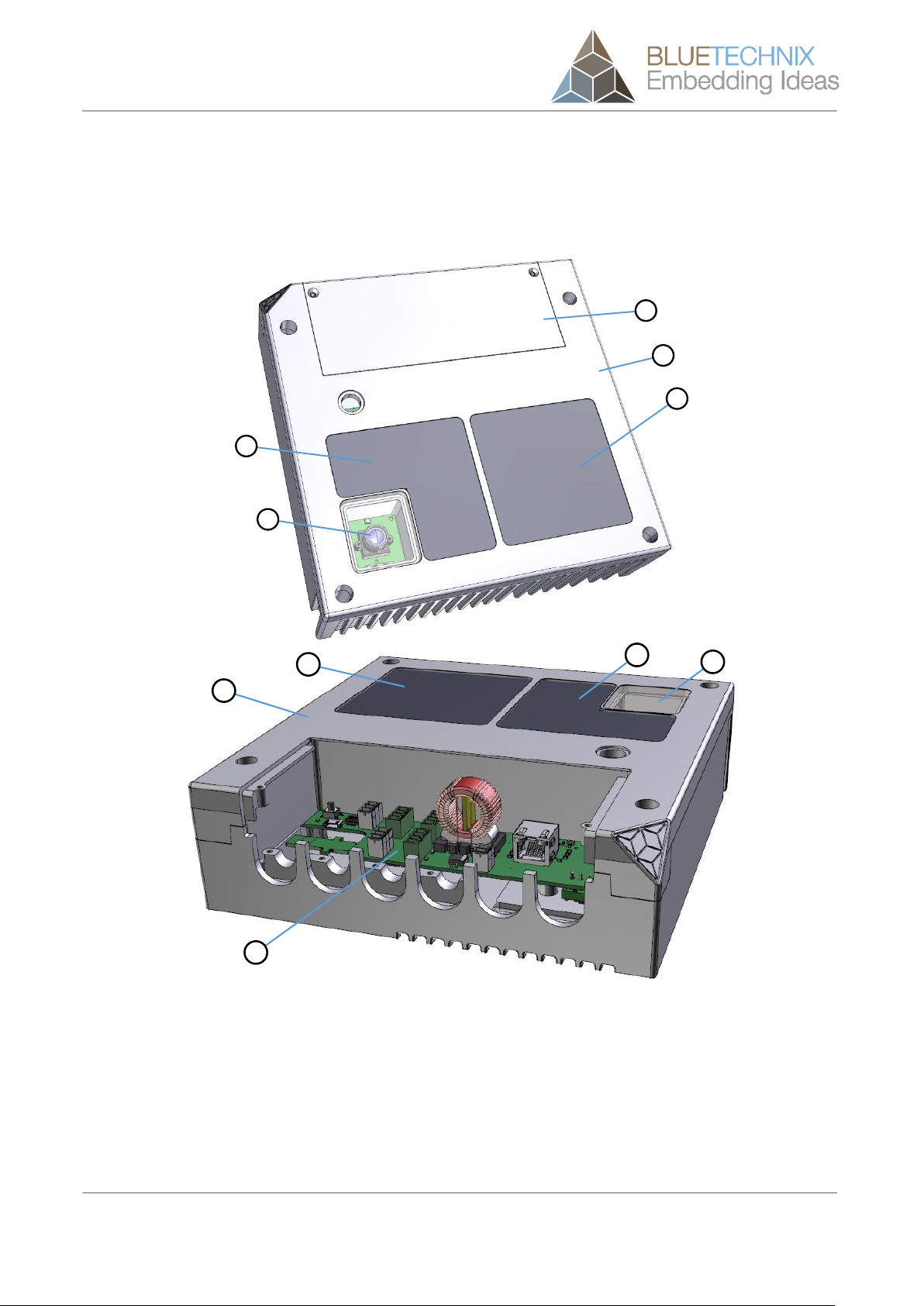
2.1 Components.............................................................................................................................. 8
2.2 Interfaces and Connectors........................................................................................................ 9
3Hardware Installation ..................................................................................................................... 10
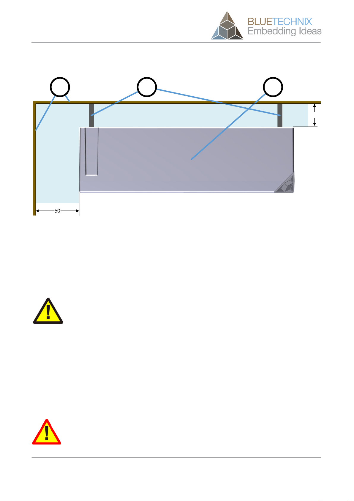
3.1 Mounting ................................................................................................................................. 10
3.1.1 Mounting Holes (a)........................................................................................................... 10
3.1.2 Mount Spacing................................................................................................................. 11
3.2 Lens and focus........................................................................................................................ 11
3.3 External ToF-Flash .................................................................................................................. 11
4Interface Description ...................................................................................................................... 13
4.1 Signal naming.......................................................................................................................... 13
4.2 Connector Numbering............................................................................................................. 13
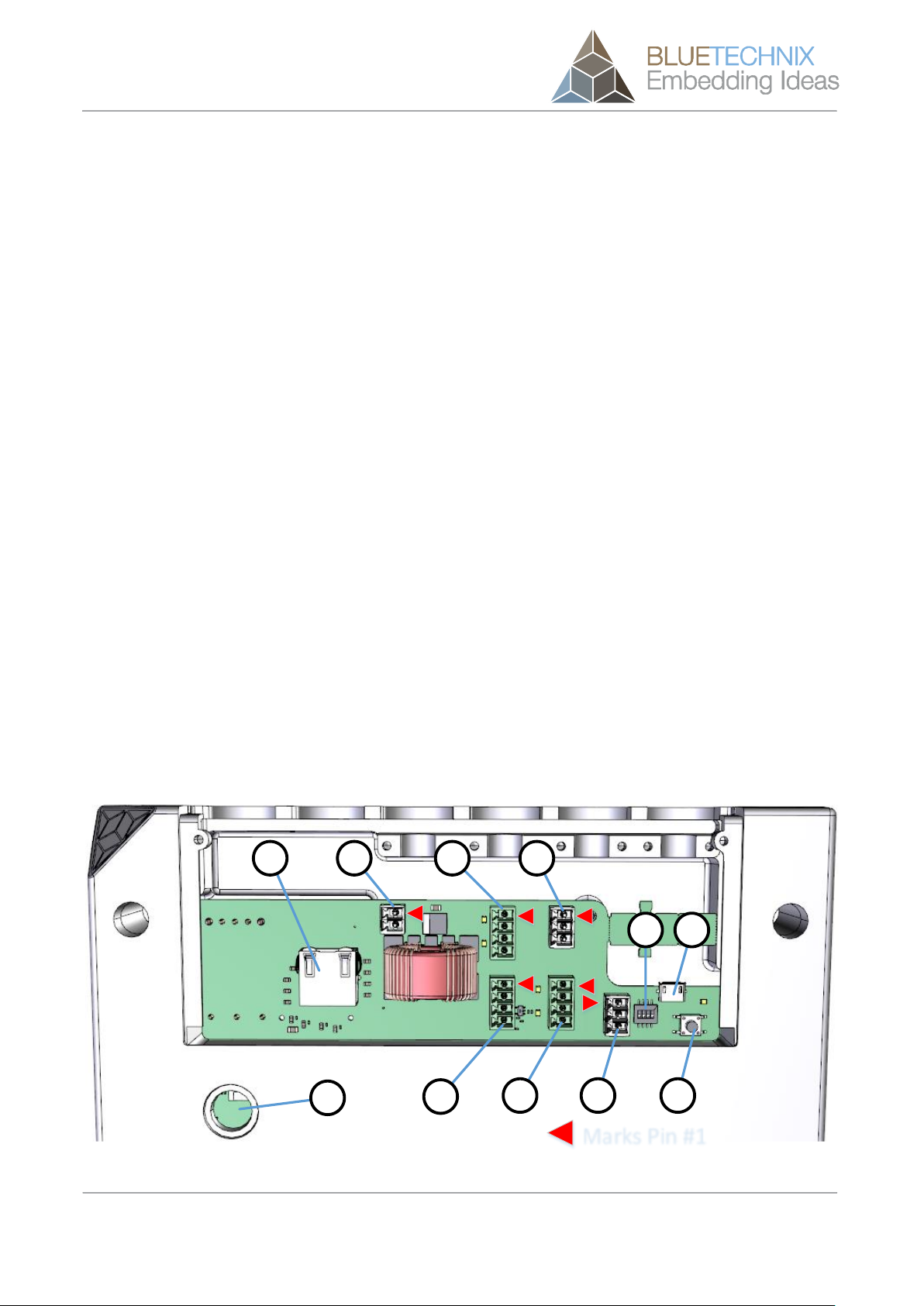
4.3 Interface-Slot........................................................................................................................... 13
4.3.1 Power Connector (a) ........................................................................................................ 14
4.3.2 Ethernet (b)....................................................................................................................... 14
4.3.3 General purpose input 1 & 2 (c) ....................................................................................... 14
4.3.4 General purpose output 1 & 2 (d) .................................................................................... 15
4.3.5 Modulation Light Interface (e) .......................................................................................... 15
4.3.6 Trigger (f) .......................................................................................................................... 16
4.3.7 RS232/RS485 (g) ............................................................................................................. 16
4.3.8 DIP-Switch (h) .................................................................................................................. 17
4.3.9 Reset-Button (i) ................................................................................................................ 17
4.3.10 Debug-UART (j)................................................................................................................ 17
4.3.11 Status LED (k) .................................................................................................................. 17
5Software ......................................................................................................................................... 18
5.1 Firmware ................................................................................................................................. 18
5.2 Demo Application.................................................................................................................... 18
5.3 Getting Started Software Development Example................................................................... 18
5.4 Camera Firmware Development KITs ..................................................................................... 18
6Appendix ........................................................................................................................................ 19
6.1 Operating Conditions .............................................................................................................. 19
6.1.1 Input current..................................................................................................................... 19
6.2 Optical Characteristics............................................................................................................ 19

© Bluetechnix 2015
6.3 Measurement Specifications .................................................................................................. 20
6.3.1 Measurement Environmental Conditions ........................................................................ 20
6.3.2 Typical Reproducibility .................................................................................................... 20
6.3.3 Typical Integration Time .................................................................................................. 20
6.3.4 Typical Range .................................................................................................................. 21
6.3.5 Accuracy of Distances ..................................................................................................... 21
6.4 Environmental considerations................................................................................................. 21
6.4.1 Temperature on the Cooling Plate................................................................................... 21
6.4.2 Integration Time vs. Frame-rate ...................................................................................... 22
6.5 Mechanical Outline.................................................................................................................. 22
7Support........................................................................................................................................... 24
7.1.1 General Support............................................................................................................... 24
7.2 Software Packages ................................................................................................................. 24
7.3 Related Products .................................................................................................................... 24
8Product History .............................................................................................................................. 25
8.1 Version Information ................................................................................................................. 25
8.1.1 Argos3D-P320 ................................................................................................................. 25
8.2 Anomalies................................................................................................................................ 25
8.3 Document Revision History .................................................................................................... 25
9Index............................................................................................................................................... 26

© Bluetechnix 2015
© Bluetechnix GmbH 2015
All Rights Reserved.
The information herein is given to describe certain components and shall not be considered as a guarantee
of characteristics.
Terms of delivery and rights of technical change reserved.
We hereby disclaim any warranties, including but not limited to warranties of non-infringement, regarding
circuits, descriptions and charts stated herein.
Bluetechnix makes and you receive no warranties or conditions, express, implied, statutory or in any
communication with you. Bluetechnix specifically disclaims any implied warranty of merchantability or fitness
for a particular purpose.
Bluetechnix takes no liability for any damages and errors causing of the usage of this board. The user of this
board is responsible by himself for the functionality of his application. He is allowed to use the board only if
he has the qualification. More information is found in the General Terms and Conditions (AGB).
Information
For further information on technology, delivery terms and conditions and prices please contact Bluetechnix
(http://www.bluetechnix.com).
Warning
Due to technical requirements components may contain dangerous substances.

User Manual - Argos3D-P320 Last change: 31 August 2015
Version 0.4
© Bluetechnix 2015 Page 6 | 26
1General Information
This guide applies to the Argos3D-P320 camera platform from Bluetechnix GmbH. Follow this guide chapter
by chapter to set up and understand your product. If a section of this document only applies to certain
camera parts, this is indicated at the beginning of the respective section.
The document applies to X-Grade product from V1.0.
1.1 Symbols Used
This guide makes use of a few symbols and conventions:
Warning
Indicates a situation which, if not avoided, could result in minor or moderate injury and/or
property damage or damage to the device.
Caution
Indicates a situation which, if not avoided, may result in minor damage to the device, in
malfunction of the device or in data loss.
Note
Notes provide information on special issues related to the device or provide information that will
make operation of the device easier.
Procedures
A procedure always starts with a headline
1. The number indicates the step number of a certain procedure you are expected to
follow. Steps are numbered sequentially.
This sign indicates an expected result of your action.
References
This symbol indicates a cross reference to a different chapter of this manual or to an
external document.

User Manual - Argos3D-P320 Last change: 31 August 2015
Version 0.4
© Bluetechnix 2015 Page 7 | 26
1.2 Certification
X-Grade Version
X-Grade version of the products are not intended for sale and have therefore no certifications.
The user is responsible for a correct usage in order with federal laws.

User Manual - Argos3D-P320 Last change: 31 August 2015
Version 0.4
© Bluetechnix 2015 Page 8 | 26
2Overview
2.1 Components
a
d
e
b
c
f
dbc
a
Figure 2-1 Argos3D-P320 components
a. Case
b. Viewing window for 3D sensor
c. Viewing window for 2D sensor
d. Viewing window for illumination module
e. Interface cover
f. Interface board

User Manual - Argos3D-P320 Last change: 31 August 2015
Version 0.4
© Bluetechnix 2015 Page 9 | 26
2.2 Interfaces and Connectors
Marks Pin #1
b a c f
ed g i
h j
k
Figure 2-2: Argos3D-P320 connectors and interfaces
a. Power supply
b. Ethernet (RJ45) 10/100/1000Base-T with PoE++
c. General purpose inputs, galvanic isolated
d. General purpose outputs, galvanic isolated
e. Modulation Light Interface
f. Trigger
g. RS232/485
h. DIP-Switch
i. Reset-Button
j. Debug-UART
k. Status LED

User Manual - Argos3D-P320 Last change: 31 August 2015
Version 0.4
© Bluetechnix 2015 Page 10 | 26
3Hardware Installation
3.1 Mounting
Caution
Case may become hot!
180.0
161.0
a
Figure 3-1: Mounting holes for the case
3.1.1 Mounting Holes (a)
The case has four holes for up to M5 screws that allows mounting the Argos3D-P320.

User Manual - Argos3D-P320 Last change: 31 August 2015
Version 0.4
© Bluetechnix 2015 Page 11 | 26
3.1.2 Mount Spacing
30
b ac
Figure 3-2: Distance to mounted wall
a. Argos-P320
b. Spacers
c. Wall or mounting panel
To maintain a natural air flow behind the Argos-P320, the device should not be mounted closer than 30 mm
to the mounting panel. A keep-out area of at least 50 mm on the four small sides must be provided as well.
Caution
The user is responsible to take care for an appropriate cooling.
3.2 Lens and focus
TBD
3.3 External ToF-Flash
In case you want to use the external ToF-Flash or another external light source you can connect them to the
Modulation Light Interface (see chapter 4.3.5).
Warning
Before connecting an external ToF-Flash, all internal LIMs must be removed beforehand.
Usage of an external ToF-Flash is only safe under certain conditions. Please contact

User Manual - Argos3D-P320 Last change: 31 August 2015
Version 0.4
© Bluetechnix 2015 Page 12 | 26
Bluetechnix support for more information.

User Manual - Argos3D-P320 Last change: 31 August 2015
Version 0.4
© Bluetechnix 2015 Page 13 | 26
4Interface Description
4.1 Signal naming
Signal names are usually written in capital letters. They are noted in positive logic (positive asserted). If the
signal is negative asserted an “n” will be added as prefix to the signal name.
Type:
The type describes the electrical characteristics of the signal. The following types are available:
I Input
O Output
DN Negative Differential Output
DP Positive Differential Output
P Power supply
3.3V TTL TTL compatible signal with 3.3V high level and 0V low level
5V tolerant Accepts 5V input level
4.2 Connector Numbering
All pins no. 1 of each connector are marked in the figures with a red arrow. The connector numbering always
starts at this pin, continuing in this row, and going backwards at the opposite side.
4.3 Interface-Slot
Marks Pin #1
b a c f
ed g i
h j
k
Figure 4-1: Argos3D-P320 connector location

User Manual - Argos3D-P320 Last change: 31 August 2015
Version 0.4
© Bluetechnix 2015 Page 14 | 26
a. Power Connector
b. Ethernet
c. General purpose input 1 & 2
d. General purpose output 1 & 2
e. Modulation Light Interface
f. Trigger
g. RS232 / RS485
h. DIP-Switch
i. Reset-Button
j. Debug-UART
k. Status LED
4.3.1 Power Connector (a)
This 3.5mm terminal connector allows plugging a cable entry plug like 691361100002 from Würth Elektronik.
Compatible connectors from other manufacturers may be found as well.
No.
Signal
Type
Description
1
VIN
P
Positive power supply
2
GND
P
Power ground
Table 4-1: Power connector description
The pins of the power connector are protected against wrong polarity.
Voltage range: 18V to 30V.
Note
Use inherently limited power sources only!
4.3.2 Ethernet (b)
This is a standard straight RJ45 10/100/1000 Base-T compatible Ethernet connector.
4.3.3 General purpose input 1 & 2 (c)
This 4 pole 3.5mm terminal connector allows plugging a cable entry plug like 691361100004 from Würth
Elektronik.
No.
Signal
Type
Description
1
IN2A
I (0V to 50V)
Relay contact A
2
IN2B
I (0V to 50V)
Relay contact B
3
IN1A
I (0V to 50V)
Relay contact A

User Manual - Argos3D-P320 Last change: 31 August 2015
Version 0.4
© Bluetechnix 2015 Page 15 | 26
No.
Signal
Type
Description
4
IN1B
I (0V to 50V)
Relay contact B
Table 4-2: General purpose input 1 & 2 connector description
An optocoupler SFH6286-2T from Vishay is used for each general purpose input.
OFF-Range: 0V to 2V.
ON-Range: 5V to 50V.
4.3.4 General purpose output 1 & 2 (d)
This 4 pole 3.5mm terminal connector allows plugging a cable entry plug like 691361100004 from Würth
Elektronik.
No.
Signal
Type
Description
1
OUT1A
SPST-A
Relay contact A
2
OUT1B
SPST-B
Relay contact B
3
OUT2A
SPST-A
Relay contact A
4
OUT2B
SPST-B
Relay contact B
Table 4-3: General purpose output 1 & 2 connector description
A solid state relay ASSR-3210 from Avago Technologies is used for each general purpose output.
Voltage range: 18V to 30V.
Current range: 0mA to 200mA.
4.3.5 Modulation Light Interface (e)
This 4 pole 3.5mm terminal connector allows plugging a cable entry plug like 691361100004 from Würth
Elektronik.
No.
Signal
Type
Description
1
MOD_N
DN
Modulation signal output-
2
MOD_P
DP
Modulation signal output+
3
GND
P
Power ground
4
OWIRE
I/O (3V3 TTL)
1-Wire communication interface
Table 4-4: Modulation Light Interface connector description
The Modulation Light Interface provides the modulation signal for an external illumination module (differential
LVDS) as well as a 1-Wire communication interface.
Caution
Overvoltage on the Modulation Light Interface will destroy the Argos3D-P320.

User Manual - Argos3D-P320 Last change: 31 August 2015
Version 0.4
© Bluetechnix 2015 Page 16 | 26
Warning
Before connecting an external ToF-Flash, all internal LIMs must be removed beforehand.
Usage of an external ToF-Flash is only safe under certain conditions. Please contact
Bluetechnix support for more information.
4.3.6 Trigger (f)
This 3 pole 3.5mm terminal connector allows plugging a cable entry plug like 691361100003 from “Würth
Elektronik”.
No.
Signal
Type
Description
1
TriggerOUT
OD (10k pull-up to 5V)
Trigger Output
2
TriggerIN
I (10V to 30V)
Trigger Input
3
GND
P
Power ground
Table 4-5: Trigger connector description
Note
The usage of this interface may depend on the firmware version.
4.3.7 RS232/RS485 (g)
This 3 pole 3.5mm terminal connector allows plugging a cable entry plug like 691361100003 from Würth
Elektronik.
No.
Signal
Type
Description
1
GND
P
Signal Ground
2
RS232 RxD1)
RS485 A/Y
IO
DN
RS232 Receive Data
RS485 Negative Differential Data
3
RS232 TxD1)
RS485 B/Z
IO
DP
RS232 Transmit Data
RS485 Positive Differential Data
Table 4-6: GPIO Connector Description
1) The interface mode can be selected with the DIP-Switch (see chapter 4.3.7).
The RS232 interface is running in full duplex mode and the RS485 is running in half duplex mode.
Note
The usage of this interface may depend on the firmware version.

User Manual - Argos3D-P320 Last change: 31 August 2015
Version 0.4
© Bluetechnix 2015 Page 17 | 26
4.3.8 DIP-Switch (h)
The DIP-Switch allows configuring the RS232/RS485 transceiver. The following table shows the functionality
of each switch.
No.
Name
Description
1
-
Not used
2
-
Not used
3
RS485 Enable
ON: Transceiver works in RS485 mode
OFF: Transceiver works in RS232 mode
4
RS485 Termination
ON: Enables the 120Ω RS485 termination resistor
OFF: No termination resistor is active
Table 4-7: DIP-Switch Description
4.3.9 Reset-Button (i)
This button can be used to perform a hardware reset and a factory default reset.
For further information about the factory default reset function see Software User Manual of the Argos3D-
P320.
4.3.10 Debug-UART (j)
This Micro-USB connector provides a Debug-UART interface to the camera.
A FT234 from FTDI is used as UART-to-USB-Converter.
4.3.11 Status LED (k)
The Status LED indicates whether the power supply is within the specified range (green), or not (red).
Additional functionalities may be firmware dependent. Please refer to the Software User Manual for
additional information.
Note
Make sure that the termination resistor is always disabled, if the driver runs in RS232 mode.

User Manual - Argos3D-P320 Last change: 31 August 2015
Version 0.4
© Bluetechnix 2015 Page 18 | 26
5Software
5.1 Firmware
For a description of the firmware related interfaces, protocol descriptions, register settings, etc. please refer
to the Software User Manual.
5.2 Demo Application
For the first evaluation of the camera and to evaluate different settings and configurations a .NET demo
application for Microsoft Windows is provided: BLT-ToF-Suite. The demo application can be downloaded
from our support web site.
Software and documentation
TBD
5.3 Getting Started Software Development Example
To facilitate the integration of the Argos module in your own application a getting started example will be
available on our download site. Please refer to our support site.
Software and documentation
TBD
5.4 Camera Firmware Development KITs
The camera offers the possibility to bring your own application onto the Argos3D-P320. Using the quad core
i.MX6 processor from Freescale Inc., one core is reserved for the calculation of the depth data, the other
cores can be used by customers for their own applications.
The Argos3D-P320 is based on an embedded Linux system.

User Manual - Argos3D-P320 Last change: 31 August 2015
Version 0.4
© Bluetechnix 2015 Page 19 | 26
6Appendix
6.1 Operating Conditions
Symbol
Parameter
Min
Typical
Max
Unit
VIN
Input supply voltage
18
24
30
V
IIN
Input current 1)
TBD
TBD 1)
TBD
mA
Input current without Interface-Board 1)
TBD
TBD
TBD
mA
Input current (Mainboard only) 3)
TBD
TBD
TBD
mA
T
Operating Temperature 2)
TBD
TBD2)
°C
T
Storage Temperature
-40
+125
°C
FITP4)
Frame-rate Integration Time Product
TBD
Table 6-1: Operating Conditions
1) Note
Valid for a frame-rate of 40fps and an integration time of 1500µs. The input current depends on
the applied frame-rate and integration time.
2) Note
The maximum operating temperature depends on the frame-rate and integration time.
6.1.1 Input current
The input current depends on the selected frame-rate (fps) and the integration time (tINT). The following figure
shows typical values. The values for the x axis shows the FITP which has been calculated with the following
equation:
TBD
Figure 6-1: Input power depending on frame-rate integration time product
6.2 Optical Characteristics
Symbol
Parameter
Min
Typical
Max
Unit
#LEDs
Nr. of LEDs
12
ΛCENTROID
Centroid-Wavelength of Illumination
850
nm
Δλ
Spectral Bandwidth
30
nm
Ie
Radiant intensity
W/sr
FoVH
Horizontal Field of View
90
Deg
FoVV
Vertical Field of View
67
Deg

User Manual - Argos3D-P320 Last change: 31 August 2015
Version 0.4
© Bluetechnix 2015 Page 20 | 26
6.3 Measurement Specifications
6.3.1 Measurement Environmental Conditions
All the following measurements have been acquired at the following constant environmental conditions.
Parameter
Value
Temperature
23 °C
Humidity
35 %
Ambient light
2 kLux
Modulation Frequency
20 MHz
Frame-rate
25 fps
Table 6-2: Environmental Specification
6.3.2 Typical Reproducibility
TBD
The following table shows the standard deviation over 100 samples.
Measuring range
[mm]
White target (90%)
[mm]
Integration time
[ms]
Gray target (18%)
[mm]
Integration time
[ms]
100
TBD
TBD
300
TBD
TBD
500
TBD
TBD
700
TBD
TBD
900
TBD
TBD
1100
TBD
TBD
1300
TBD
TBD
1500
TBD
TBD
1700
TBD
TBD
1900
TBD
TBD
2100
TBD
TBD
2300
TBD
TBD
2500
TBD
TBD
2700
TBD
TBD
2900
TBD
TBD
Table 6-3: Typical Reproducibility
6.3.3 Typical Integration Time
Measuring range [mm]
Integration time for white target
(90%) [ms]
Integration time for gray target
(18%) [ms]
500
TBD
TBD
1000
TBD
TBD
1500
TBD
TBD
2000
TBD
TBD
2500
TBD
TBD
3000
TBD
TBD
Table 6-4: Typical Integration Time
Table of contents
Other Blue Technix Control Unit manuals

Blue Technix
Blue Technix CM-BF537E Instructions for use

Blue Technix
Blue Technix ADEV-BF52xC V1.1 Instructions for use

Blue Technix
Blue Technix Sentis3D-M530 Instructions for use

Blue Technix
Blue Technix Sentis ToF-P510 Instructions for use

Blue Technix
Blue Technix CM-BF527 Instructions for use

Blue Technix
Blue Technix TIM-UP-19k-S3-Spartan 6 User manual