Y-E Data YD-380 User manual

VY·E
DATA
MAINTENANCE
MANUAL
YD-380
HALF
HEIGHT,
HIGH
DENSITY,
DOUBLE
SIDED
5.25
INCH
FLEXIBLE
DISK
DRIVE
Contents
of
this
manual
may
be
changed
without
notice.
Check
the
revision
number when
placing
an
order.
September
1983
FDL-523006
REV.
A

---
Date
..
~ptember
--
--
-
.-
-
--
-
~ote:
I~"
('21
Revisions
Rev.
Description
Revised
Pages
83 A
First
Edition
publication
----~e
YD-380
may
be
referred
to
as
simply
a
"drive".
~=~e
5.25
inch
flexible
disk
may
be
referred
to
as
simply
~
-.
disk.

YD-380
Maintenance Manual
TABLE
OF
CONTENTS
1.0
INTRODUCTION
2.0
MAINTENANCE
TOOLS
AND
TEST
EQUIPMENT
2.1
Maintenance Tool
List
2.2
Maintenance
Supplies
List
2.3
Test
Equipment
2.4
Exerciser
3.0
PREVENTIVE
MAINTENANCE
3.1
General
3.2
Visual
Check
3.3
Cleaning
4.0
SERVICE
CHECKS,
REPLACEMENT
AND
ADJUSTMENT
Maintenance
Level
1
4.1
PWB
4.2
Index Sensor Assembly
4.3
Track 00
Sensor
Assembly
4.4
Write
Protect
Sensor
Assembly
4.5
Media Sensor Assembly
4.6
In
Use
Lamp
Assembly
Page
1
1
1
2
2
2
3
3
3
3
4
5
6
9
11
12
14
TABLE
OF
CONTENTS
~Aintenance
Level. 2
4.7
Carrier
Assembly
4.8
Index
Lamp
Assembly (on Motor
Control
PWB)
4.9
Drive
Motor Assembly (on Motor
Control
PWB)
4.10
Head Load
Solenoid
4.11.
Front
Lever
4.12
Front
Bezel
4.13
Stepper
Assembly
4.14
Head/Carriage
Assembly
5.0
PARTS/ASSEMBLIES
PHYSICAL
LOCATIONS
6.0
TEST
POINT/CONNECTOR
PIN
ASSIGNMENTS
7.0
SPARE
PARTS
LIST
8.0
SCHEMATIC
DIAGRAMS
9.0
EXPLODED
VIEW
10.0
USING
A
CLEANING
DISK
Page
15
16
17
18
21
U
23
24
30
35 .
38
39
42
43

1.0
INTRODUCTION
This
manual
describes
the
maintenance
and
operation
of
the
Y-E
DATA
YD-380
two
sided,
high
density,
5.25
inch
Floppy
Disk
Drive.
Included
is
information
on
service
checks,
removal and
replace-
ment
procedures,
and
also
adjustment
instructions
for
customers'
engineers.
2.0
MAINTENANCE
TOOLS
AND
TEST
EQUIPMENT
The
following
tables
list
the
maintenance
tools,
maintenance
supplies,
test
equipment and
exerciser
for
the
YO-38D.
2.1
Maintenance
Tools
List
TOOL
Y-E
DATE
PIN
Phillips
Screwdriver
(for
M3)
141034-01
Phillips
Screwdriver
(for
M2.6) 141627-01
Flat
Head
Screwdriver
141035-01
Cutters
141039-01
Needle Nose
Pliers
141040-01
Tweezers 141042-01
CE
Disk
145173-01
Cleaning
Disk
145174-01
Hex
Wrench
1.27
mm
140266-03
Hex
Wrench
1.5
mm
140266-01

2.2
Maintenance
Supplies
Supplies
Y-E
DATA
PIN
Tie
Wrap
(TY-23M,
Kitagawa)
031005-01
2.3
Test
Equipment
Test
Equipment
Multimeter
Electronic
Counter*
Oscilloscope*
*
For
use
at
Maintenance
Level
2
2.4
Exerciser
Equipment
Exerciser
Y-E
DATA
PIN
YD-164T
3
.0
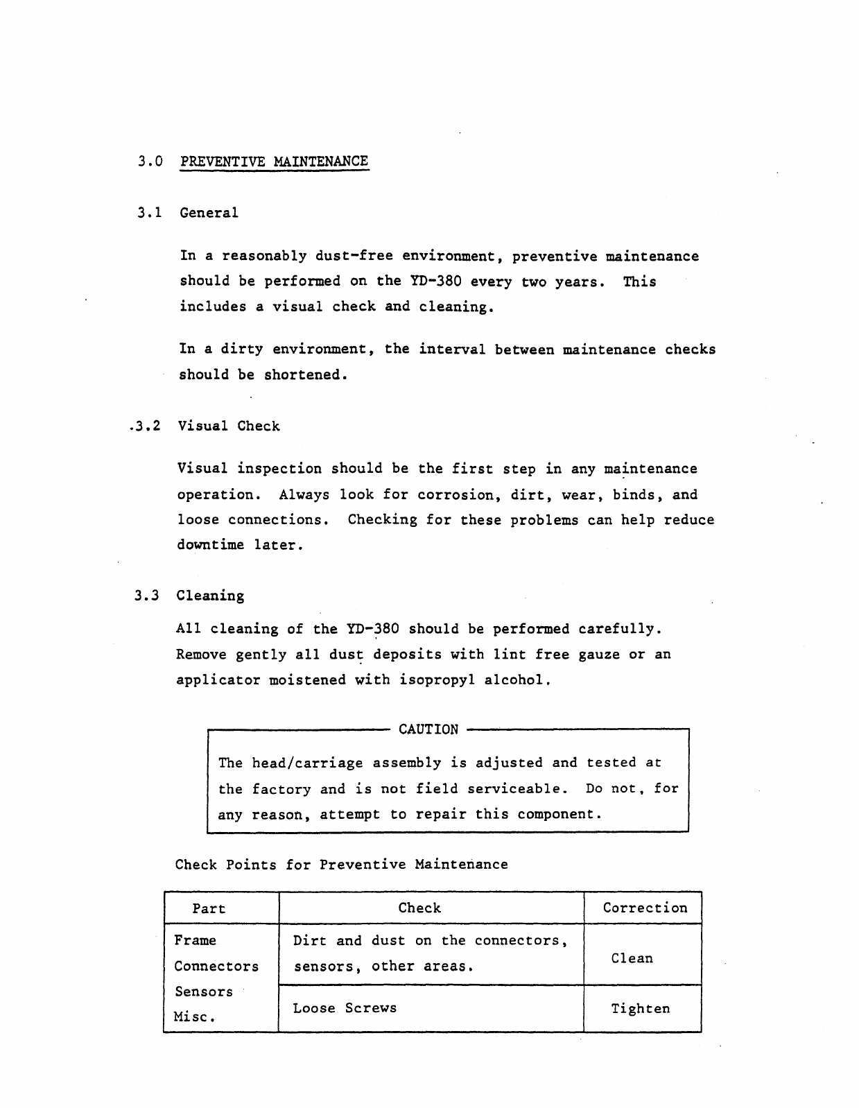
PREVENTIVE
MAINTENANCE
3.1
General
In
a
reasonably
dust-free
environment,
preventive
maintenance
should
be
performed
on
the
YD-380
every
two
years.
This
includes
a
visual
check
and
cleaning.
In
a
dirty
environment,
the
interval
between
maintenance
checks
should
be
shortened
•
.
3.2
Visual
Check
Visual
inspection
should
be
the
first
step
in
any
ma~ntenance
operation.
Always
look
for
corrosion,
dirt,
wear,
binds,
and
loose
connections.
Checking
for
these
problems
can
help
reduce
downtime
later.
3.3
Cleaning
All
cleaning
of
the
YD-380
should
be
performed
carefully.
Remove
gently
all
dus~
deposits
with
lint
free
gauze
or
an
applicator
moistened
with
isopropyl
alcohol.
CAUTION
The
head/carriage
assembly
is
adjusted
and
tested
at
the
factory
and
is
not
field
serviceable.
Do
not,
for
any
reason,
attempt
to
repair
this
component.
Check
Points
for
Preventive
Maintenance
Part
Check
Correction
Frame
Dirt
and
dust
on
the
connectors,
Connectors
other
areas.
Clean
sensors,
Sensors
Misc.
Loose
Screws
Tighten

4.0
SERVICE
CHECKS,
REPLACEMENTS
AND
ADJUSTMENTS
This
chapter
contains
detailed
maintenance
procedures
for
the
assemblies
listed
below.
Note
that
the
list
is
separated
into
two
maintenance
levels:
Levell:
Level
2:
Can
be
performed
without
special
training
or
tools.
Special
training
and
tools
required.
Level
1
4.1
PWB
4.2
Index
Sensor
4.3
Track
00
Sensor
4.4
Write
Protect
Sensor
4.5
Media
Sensor
4.6
In
Use
Lamp
Level 2
4.7
Carrier
4.8
Index
Lamp
(on Motor
Control
PWB)
4.9
Drive
Motor (on Motor
Control
PWB)
4.10
Head Load
Solenoid
4.11
Front
Lever
4.12
Front
Bezel
4.13
Stepper
4.14
Head/Carriage
Assembly
Note:
Refer
to
Chapter
5
for
Parts/Assemblies
Locations,
Chapter
6
for
Test
Points/Connector
Pin
Assignments and
Chapter
9
for
Exploded View.
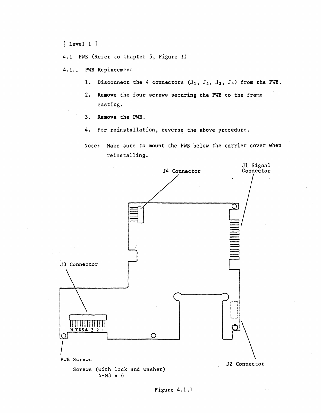
[
Levell]
4.1
PWB
(Refer
to
Chapter
5,
Figure
1)
4.1.1
PWB
Replacement
1.
Disconnect
the
4
connectors
(J1,
J2'
J3,
J4)
from
the
PWB.
2.
Remove
the
four
screws
securing
the
PWB
to
the
frame
casting.
3.
Remove
the
PWB.
4.
For
reinstallation,
reverse
the
above
procedure.
Note:
Make
sure
to
mount
the
PWB
below
the
carrier
cover
when
reinstalling.
J4
Connector
J3
Connector
o
I
PWB
Screws
Screws
(with
lock
and
washer)
4-M3
x6
Figure
4.1.1
Jl
Signal
Connector
,--,
I ,
, I
,:
I ,
--
J2
Connector
4.2
Index
Sensor
Assembly
(Refer
to
Chapter
5,
Figure
3)
4.2.1
Service
Check~
1.
Power
up
the
drive.
2.
Without
inserting
a
disk,
move
the
lever
to
lock
position
and
check
for
a
to
0.5
V
between
the
PWB
connector
J3
Pin
All
and G
(GND).
Next,
insert
a
disk
and
close
the
door;
the
vol
tage
at
the
same
points
should
be
2.5
to'
5.25
V'.
4.4.2
Replacement
1.
Remove
the
PWB
(Refer
to
4.1)
2.
Remove
J3
connector
housing
6.
(Refer
to
Page
9,
figure
4.2.2)
3.
Take
out
the
carrier
cover
screws
and remove
the
carrier
cover.
'
4.'
Lift,
up
the
lead
clamps
slightly
and
pullout
the
leads.
5.
Remove
the
In
Use Lamp.
6.
Take
out
the
screws
for
the
front
lever
and
carrier
assem-
bly,
and remove
the
front
lever
and
carrier
assembly.
7.
Take
out
the
screws
to
the
Write
Protect
Sensor
assembly,
and
as
shown
in
figure
4.4.1,
remove
the
write
protect
sensor
assembly
by
pushing
in
the
direction
indicated.
CAUTION
When
clamping
the
leads,
be
careful
not
to
damage
the
lead
insulation.
8.
For
reinstallation,
reverse
the
above
procedure.
9.
Perform
a
service
check.
(See
4.l.l)
Note:
Make
sure
the
front
edge
of
the
carrier
plate
spring
arm
securing
the
Ready/Off
plate
does
not
come
in
contact
with
the
leads.
Table of contents


