Yachting Electronic Co. NAKI8850B User manual

NAKI8850B
www.goyachting.cn
User’s manual
MENU
EXIT
ENT
T910
NAKI8850B 100M
T810
(optional)


All right reserved! Except as expressly provided herein,
no part of this manual may be copied, reproduced, repub-
lished, transmitted or distributed for any purpose, without
prior written consent of Yachting Electronic Co., Ltd.
Yachting Electronic may find it necessary to change or end
our policies, regulations, and special offers at any time.
We reserve the right to change or improve its products and
to make changes in the content without obligation to notify
any person or organization.
For current updates or other information, please visit our
website:
www.goyachting.cn
www.goyachting.cn
Yachting Electronic Co., Ltd
Building107, No.508, Heyan Road,
Nanjing, 210038, China
Printed in China
Copyright 2008 Yachting Electronic Co., Ltd.
All rights reserved.
i

Content
Content
Introduction ......................................................................1
Packing list........................................................................2
General attention...............................................................2
Understanding Sonar.........................................................3
Installation.........................................................................5
Installing the battery.....................................................5
Installing the transducer...............................................7
Transom installation..............................................7
(for T810 transducer)
Shoot-thru-hull installation.................................16
(for T810 transducer)
IceEDQN fishing installation..............................21
(for T910 transducer)
Using the transducer......................................22
Ice fishing......................................................23
Boat fishing...................................................25
Operational Panel Basic..................................................27
Display............................................................................28
ii

Understanding the display.........................................28
Depth Range..............................................................29
Water surface line......................................................30
Operation........................................................................32
Menu Operation Instruction......................................32
Sensitivity..................................................................34
Chart Speed...............................................................35
Shallow......................................................................36
Depth Range..............................................................37
Fish ID.......................................................................38
Units..........................................................................39
Backlight...................................................................40
Contrast.....................................................................41
Load DFT..................................................................42
Trouble Shooting............................................................43
Maintenance...................................................................47
Guarantee Conditions.....................................................48
iii

Specfications and Feature...............................................49
Specfications...................................................................49
Features...........................................................................50
Contact us........................................................................51
iv

Introduction
Introduction
Thank you for choosing our Fish Finder. and welcome
to the innovations of Yachting Electronic Co., Ltd! We has
been committed to fish finder R&D activities all the way
and its products have been reputed for their cutting-edge
technologies and reliable performance.
The unit is designed to facilitate fishing on the bank, along
the seashore,and on-board in a variety of water areas.
We offer one year charge-free main-tenance against any
damages induced by non-human factors; and damages
beyond the six months are handled with reasonable charges
based on concrete situations. For details regarding maint-
enance
service,
please refer to the warranty explanations.
To familiarize yourself better with the product’s operation
and maximize the utilization, we invite you to read the
User’s Guide carefully.
For any possible problems you may encounter during the
operation, please switch to the Trouble shooting section
for reference.
1

Packing list
Packing list
The following items are included in the gift box:
1) A handheld with 3” Dot matrix LCD
2) A transducer with 6m cable
3) A copy of User’s Guide
Note:
Note:
the standard matched transducer of NAKI8850B is
T910, which can be used with ice/bank fishing. However
there is another T810 transducer can be used in boat fishing,
which is optional for customer.
In the event that any of the items listed is found missing,
call us immediately or log on to our website at
www.goyachting.cn. Clients located in other parts of the
world may also refer to their respective local distributors.
General attention
General attention
War
War
ning
ning
: Disassembly and maintenance are only to be
performed by professionals designated by the Company.
Any of the following situations can void the remainder of
your warranty: unauthorized disassembly or maintenance,
damage or alteration to the production serial number, etc.
2

Warn
Warn
ing:
ing:
Although the unit is designed waterproof, it is
strongly warned not
immerge it into in water, whcih may
cause damage of inner electronic part.
Under
Under
standing s
standing s
onar
onar
If you are familiar with how sonar works, skip ahead to the
next segment. But, if you have never owned sonar Fishfinder
before, this segment will tell you the basic working theory
about sonar.
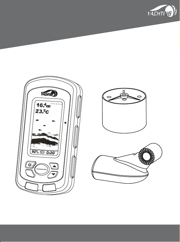
Based on the sonar techno-
logy, the Fishfinder could
detect the underwater
condition, including fish,
structure, or bottom. After
you finished the installation
of transducer and sonar unit,
connect the sonar unit to the
transducer. The transducer
sends a sound wave signal
into the water in a cone shape. At the source, the wave is
narrow; however as it penetrates deeper, the sound wave

spreads forming a cone (think flashlight). The sound wave
bounce back to the transducer when it strikes any object,
the object could be fish, structure, bottom or any other
object with density being different from the water.
The transducer amplifies the return signal and sends it
back to the Fishfinder. By measuring the time between the
transmission of the sound wave and when the sound wave
bounce back, the Fishfinder could calculate the distance by
the inner microprocessor. Then the Fishfinder display the
information on the screen for you to interpret.

1. Turn the screw anti-clockwise with a screw driver.
Then slide the Battery Door towards the bottom of the
unit and remove it from the main housing.
2. Install 4 “AAA” batteries. Be certain that the batteries
are aligned as per the diagram within the battery
compartment.
3. Slide the Battery Door towards the top of the unit until
To take off the battery
cover, put and slide it
with some strenth
Warning:
Warning:
do not split the battery cover
with strength in the vertical directiion!
Installation
Installation
Installing the battery

it is completely closed. Then turn the screw clockwise
with a screw driver until snug before continuing. Be
certain not to over-tighten it.

Installing the transducer
Trans
Trans
om installati
om installati
on (for T810 transducer)
1. Select the
1. Select the
mounti
mounti
ng location
ng location
When you select a mounting location for the transducer,
the flowing should be considered in advance.
The sonar transmission / reception can be affected severely
in turbulent water, so please do not mount transducer behind
strakes, rows of rivet, water intake, discharge port, the
immediate area of the propeller(s). These areas can create
turbulence when the boat moves in a high speed.
Do not mount the transducer in locations where it may be
vibrate severely when the boat’s engine launches or stop.
After the installation is finished, make sure the transducer is
pointed down straightly to the water surface.
2. Mark the loca
2. Mark the loca
tion and
tion and
drill the mounting holes
1) Make sure the boat is level and no obvious incline of the
shipboardDŽ
2) Hold the template against the transom of boatˈmark
two mounting holes in the two slots. The center of two

holes should be parallel
with water surface.
Make sure the distance between
the bottom of template and the
lower edge of the transom
is about 0~5mm.
3) Using a 5/32” bit, drill 2 holes approximate 1” (25mm)
deep at the marked location. Be careful not drilling too
deep then 1”.
3. As
3. As
semble
semble
the transducer
the transducer
1) Slightly spread the pivot
and match the transducer
to the pivot. The toothed
surface make them not
separating easily.
Note:
Note:
when match the
transducer and pivot, please be
a)
b)
Mark the two position
0~5mm

Locking nut
Pivot bolt
Pivot
careful not assembling them reversedly. ( see the figureˈ
a-rightˈb-wrong)
2) Put the locking nut into the slot of pivotˈthen insert the
pivot boltˈhand-tighten the pivot bolt.
Note
Note
Do not over tighten the pivot-bolt with Allen
wrench otherwise you will not being able to adjust the
angle of transducerDŽ
3) Match the pivot to the template.

Note:
Note:
Do not push the pivot into the bracket.
4. Initial installation of transducer
1) Apply marine sealant to the 4 x 15mm screws and the
two holes on transom. Hold the bracket against transom
againˈslightly tighten the template by two 4 x 15mm
screws.
Note:
Note:
Do not over tighten, otherwise you will not be able
to adjust the transducerDŽ
Do not push the
pivot into the
bracket

2) Adjust the template to make it roughly vertical to the
water surfaceˈthen tighten the two screws with Allen
wrench
3) Press the pivot into the bracket, and then rotate the
transducer to make it parallel with the water surface.
Note: The pivot match the transducer by ratchetsˈand
the increment is12 degree, so in some situations you
may find it impossible to adjust the transducer completely
parallel with the water surface. In this situation a slight
incline (1~5degree) is acceptable.
5. Rout
5. Rout
ing the ca
ing the ca
ble
ble
According to the different situation of boat, you could
choose to route the transducer through or over the transom
to the sonar unit.
If you choose to route the transducer through the transom
to the sonar unit, please follow the steps bellow:
1) hold one cable clamp at the position approximate 1/4
distance from the top of transom to the transducerˈthen
mark the position with a pencil. Using a 1/8” bit, drill

tow holes approximate 3/8” (10mm) deep.
2) Apply some marine sealant to the hole, and then tighten
the cable clamp with two screws.
3) If more than one cable clamp are needed, repeat
step1ˈ2
Note
Note˖
As the transducer is adjustableˈmake sure the cable
between the transducer and the first clamp is not tighten.
Enough slack should be remained; otherwise the transducer
cable is easily damaged. To make sure such damage will not
happenˈplease rotate the transducer to the utmost position
before tighten the first cable clamp (see figure-7).
4)
When route the transducer cable to the sonar unit, avoi
d
The template touchs the transducer

e
nwinding the transducer cable with other electrical wires
or some electrical device that may cause interference, as
this will affect the transducer’s transmission / reception
of sonar signal.
5. Test th
5. Test th
e initial in
e initial in
stallation
stallation
To get a better installation of the transducer, we suggest you
testing the initial installation and adjust the transducer
according to the test outcome.
Before the test, please make certain you have finished the
installation of the sonar unit and properly connect the
transducer cable to the sonar unit. Also make sure the distance
between the transducer and bottom is not beyond the depth
capability of your Fishfinder.
1) Power up the sonar unit and see whether there is sonar
information on display. If yes, it means the sonar unit is
properly connected to the transducer. If notˈplease
check the connection between the sonar unit and the
transducer.
2)
Firstˈrun your boat at a low speed. See the sonar

information on the screen. If the sonar display comes
out normal, then speed up your boat. Always observe
the sonar display during the course. If signal losing or
abnormal sonar display happens when the boat run at
a certain speedˈnote the speed of your boatDŽ
3) Adjust the transducer in a small scope and run the boat
at the noted speed (step 2). Then observe the sonar display.
If the sonar display is normal, go to the next step. If not,
please adjust the transducer until it comes out normal.
If by any means a normal sonar display can not be
obtained, then it is necessary for you to relocate the
position of the transducer.
7. The fi
7. The fi
nal installat
nal installat
ion
ion
1
) Make sure the transducer could be completely immersed
into water, and then adjust the location of template on
the transom to make the transducer immersed into water
as low as possible. This will make the transducer’s
transmission / reception being affected by the whirlpool
at the smallest extent when the boat runs at a high speed.
Table of contents
Other Yachting Electronic Co. Fish Finder manuals