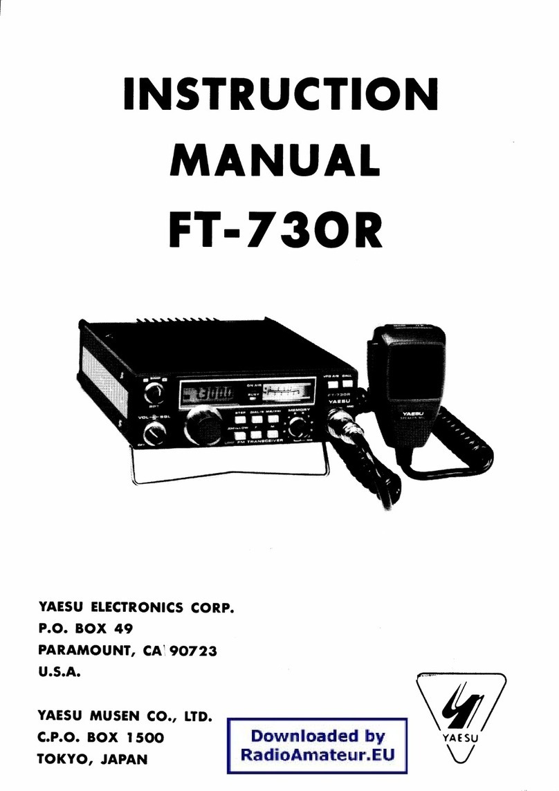
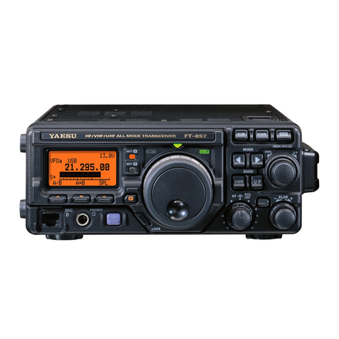
Yaesu FT-890 User manual

OPERATING
MANUAL
YAESU MUSEN
CO.,
LTD.
C.P.O.
BOX
1500
TOKYO,
JAPAN
-
4
-i
:
\\
'"

Contents
Front Panel
..
.
.
..
.
.
.
..
Fold-Out
Transmitting.
..
...
.
.
..
..
.
..
.
..
17
Meter Functions,Top Panel Controls
AutomaticAntenna Matching
SSB Transmission
&
Display
.
.
.
.
.
.
.
.
.
...
Fold-Out
MicrophoneToneSelection
Specifications.
..
..
..
...
.
..
.
2
AFSpeech Compressor 18
Accessories
&
Options
..
.
.
..
.
.
3
ATU-2
&
FC-800 AutomaticAntennaTuners 3
TCXO-3Master Reference Oscillator
3
SP-6 Loudspeaker and LL-5 Phone PatchOption 3
YH-77ST LightweightHeadphones 4
DVS2 DigitalVoice System 4
FIF-232C CAT SystemInterface 4
IFCrystal Filter Options 4
Microphones
5
Station Installation
..
.
.
..
.
..
.
6
PreliminaryInspection 6
AC Power Supply 6
Changing theAC VoltageRange of the FP-800
6
TransceiverLocation 7
Grounding 7
Adjusting the Front Panel Angle 7
Antenna Considerations 7
MobilePower Connection 7
MobileMounting 8
Mobile Antenna Installation 8
Interconnectionof Accessories
8
MemoryBackup
8
ConnectorPinouts
.
......
..
..
..
.
.
9
ConnectingExternal Accessories
..
.
.
.
.10
ConnectingaLinearAmplifier
.
.
.
.
..
11
Power-UpSettings
.
.
...
.
.
....
.
.
.
12
Operation
.
...
.
..
...
.
....
13
Getting StartedTutorial
.
.
..
.
.
.
.
.
.
.
13
Tuning
&
ScanningSteps 13
GeneralCoverage Reception 14
Displayingthe10's-of-Hz Digit 14
Button Beeper Settings 14
Dealing
with
Interference
.
..
.
.
.
...
14
Front End Selections:RF Amp
&
Attenuation 14
RF GainSetting 15
AGC-F Selection 15
Noise Blanker Setting 15
IFShiftAdjustment 15
AM
&
CWNarrow IFfilters 15
Locking the Dialor Buttons 15
IF Notch Filter 16
YF-101 SSB Crystal Filter Option 16
IF
ProcessorFrequency Shift
VOX
(Voice-Actuated T/R Switching)
CW Transmission
CW
Key or PaddleConnections
Using the InternalElectronic Keyer
Sidetone
&
Button Beeper Volume
AM Transmission
FM
Transmission
FM
Repeater Operation
Clarifier(ReceiverOffsetTuning)
VFOB
&
SplitFrequencyOperation 21
Tuning Knob TorqueAdjustment 22
MemoryFeatures
.
.
..
.
..
..
....
.
.
23
Memory Storage 23
CheckingMemory Contents 23
Frequency DisplayModes
24
ClarifyingMemories, and
M
TUNE
24
Memory Recall
&
Operation 24
Memory Scanning 25
Memory Scan Skip
25
Memory Blanking
25
SubbandScanning:Memories
PI
&
P2 25
DigitalModes
.
..
.
.
..
.
.
.
..
.
.
.
.
.
27
TU/TNC Interconnections 27
Transmitter
AF
InputRelationships
28
TransmitterAdjustment 28
FrequencyDisplay
&
Tuning
2-8
1200-Baud
FM
Packet 29
Optional DVSPDigital Voice Recorder
.
30
CAT
System Computer Control
.
.
.
31
Data Returned From FT-890 31
StatusUpdate Data Organization 31
CAT Commands 32
CodingExamples 34
InstallingInternal Accessories
..
.
35
-.
Cover Removal 36
TCXO-3Enhanced-StabilityOscillator 37
OptionalIF Crystal Filters 39
ATU-2 Internal Antenna Tuner
39
Rear Panel
..
.
.
.
.
.
.
..
.
..
.
.
42

The meter indicates the selected
parameter during transmission,
andsignalstrengthin S-unitsdur-
ing reception (on the top scale).
Each S-unit is approximately 6
dB. See the back ofthis page.
I
One of these indicatorlbuttons is al-
I
1
ways litto indicatethe function of the
multimeter during transmission.
Press an indicator to change the se-
lection. The meanings of the abbre-
viations are as follows:
ALC
relativeAutomatic Level
Control
PO
RF Power Output (watts)
SWR
Standina Wave Ratio
This buttoncan be used to manually
activate the transmitter.
It
must be in
the undepressed
(I)
positionfor re-
ception.
transmitterswitchinginvoice modes.
Related controls are on the rear
panel,and operation is described on
page 19.
This buttonturns the transceiver on
and off. To avoid switching spikes,
make sure it is offwhen you turn the
DCpowersource (AC power supply)
onor off. Ina mobileinstallation,the
transceiver should beoff when start-
ingor stopping the engine.
This '/&inch, 3-contactjack accepts
either monaural or stereo head-
phones with a
2-
or 3-contact plug.
When a plug is inserted, the loud-
speaker is disabled. Audio is sup-
plied to both channels of a stereo
headphone.
This 8-pinjack accepts the
MD-1
B8
or MD-~CEDesktop
Microphoneor the MH-188
Handie Scanning Micro-
phone. Proper microphone
input impedance is 500 to
600 ohms.
MIC
I
4r
This buttonactivates split frequencytrans-
ceive operation.The displayed frequency
is used for reception,andthe otherVFO or
rear half of the memory for transmission.
The
SPLIT
indicator at the left side of the
display is lit while this function is active.
The
TX
LED glows red
when the transmitter is
activated. The
BUSY
LED glows green when numberand specialstates. Details
are on the back of this page.
These five momentary buttons
select the operating mode, indi-
catedbythe LED ineach button.
Eachof these buttons has an LED indica-
tor to show when the function is activated.
PROC
activates the speech processor in
the SSBand AM modes. See page 18.
AGC-F
sets the receiver Automatic Gain
Controldecaytimefor fast recovery,which
can improve CW receptionandfast-fading
(QSB) SSB signals.
IPO
bypasses the receiver RF amplifier,
providing the widest dynamic range. See
page 14for details.
ATT
If
the IPOfunction is on andthe band
is noisyor very strong signals are present,
press this button to insert a 12-dBattenu-
ator inthe frontend to protectthe receiver
from overload.
RPT
activates HF FM repeater operation
on the 29-MHz band. See page 21.
The inner
AF
gain control adjusts
the volume of the receiver in the
speakeror headphones.
The outer
RF
gain control adjusts
the gain of the receiver
IF
amplifi-
ers. This controlis normallyset fully
clockwise for maximum sensitivity.
See page 15for details.
The inner
MIC
control adjusts the mi-
crophone input level for SSB and AM
transmission.
The outer
RF PWR
control sets trans-
mitter output power in all modes. The
adjustment range is from less than 10
to 100watt3 (5 to 25 watts AM).

This button toggles operation be-
tweenamemoryandaVFO. Either
VFO-A
(or
-B),
or
MEM
is dis-
played to the left of the frequency
to indicate the current selection.
If
a displayed memory has been re-
tuned, pressing this button once
returns the display to the original
memory contents, and pressing it
again returns to the (last used)
VFO.
Pressing this button while receiving in
a ham band activates the transmitter
for while the tuner rematches the an-
tennafor minimumSWR.The resulting
settings are stored in the antenna
tuner's 31 memories,for automatic re-
call later.See page
17.
Pressing this button so that its
When receiving on a VFO,
1
I
this buttontogglesoperation
anddisplaybetweenVFOs A
and
B.
On a memory, it tog-
I
I
inline.~e'ce~tionis notaffected.
The
START
button also acti-
vates the antenna tuner.
1
1
LED is lfi~utsthe antennatuner
I
'This knob tunes the operating fre-
quencyof the VFO or a recalledmem-
ory. Tuning increments are normally
10 Hz (100 Hz inAM and FM modes).
The markings on the knob represent
Front
Panel
Pressing this button momentarily
displays the contents of the cur-
rently selected memorychannelfor
three seconds. Holding this button
for
1/2
second copies all data from
the memory to the VFOs, as two
beeps sound. Previous data in the
VFOs is overwritten. See page
24.
When receivingon aVFO or a retuned
memory,holdingthis buttonfor 1/2-sec-
ond writes the current operating data
to the currentlyselected memory.Two
beepssound,and any previousdata in
the memoryisoverwritten.Also, press-
ing and holdingthis buttonafter recall-
ing a memory (without retuning)
causes the memory to be "blanked."
Repeatto unblank the memory.
memory half. Previous contents
of the non-displayedVFOlmem-
This knobtunes the clarifier offset
frequency upto
*
9.99
kHz, when
activated by the
CLAR
button to
the leftof it. Operating details are
on page21.
I
Pressingeitherof these buttonsmo-
mentarily steps the operating fre-
quency down or up one ham band,
or 100 kHz (if receiving in GEN
mode),respectively.Pressing
FAST
with one of these buttons steps
down or up 1 MHz if receiving in
GEN mode. Continue holdingeither
buttonfor repeatedstepping.
This button determines the function of
the
DOWNIUP
buttons when receiving
on a VFO or retuned memory: GEN
steps are 100kHz, and HAM steps are
from one amateur band to the next.
I-l
I
The inner
NOTCH
controladjuststhe
IFnotchfreauencvwhen activatedbv
the buttonli~~next to the label.
li
modes other than AM and FM, the
outer
SHIFT
control offsets the IF
passband center frequency from the
displayed frequency when turned
away from the 12-o'clockposition.
of the knob provides 500 increments
(5kHz,or 50 kHzin AMIFM).
1
1
25 increments each, and one full turn
I I
I,
For fast tuning, press this button while
rotatingthe tuning knob or pressing the
UP
or
DOWN
button, to increase the
tuning rate ten times. See the table on
page 13 for all available steps. When
fast tuning is active,
FAST
is displayed
above the MHz digits. You can set the
functionof this buttonto beeither"press-
and-hold",or toggle onloff, by holding it
while switchingthe transceiver on.
.
This button toggles I~ckingof the
tuning knob to prevent accidental
frequencychanges.
LOCK
appears
at the bottomleft of the display win-
dowwhen locked(theknobcanstill
be turned, but it does nothing).
Press againto re-enablethe tuning
knob. You can change the function
of this button to lock most of the
controls andbuttons,insteadof just
the tuning knob, by holdingthe but-
ton while switching the transceiver
on. In this case the
LOCK
display
will blinkwhen enabled.
The outer
SQL
control sets the sig-
nal threshold at which receiver
audio is muted(andthe
BUSY
LED
turnsoff),inall modes.Thiscontrolis
normally kept fully CCW, except
when scanning, and during FM op-
eration. Scanning stops when the
squelchis open. See page 25.
The inner
NB
control adjusts the
blanking level when the noise
blanker is activated by the indica-
torlbutton left of the label. If the con-
trol is set very far clockwise,receiver
audio may bedistorted.
Meter
Functions
Duringreception,the top
"S"
scale indicates incoming
signal strength in S-units at
the left endof the scale, and
in dB above S-9 at the right
end. Each S-unitis approxi-
mately
6
dB.
Note:
Whilereceiving,refer only to
the S-meter function:the topscale of
the meter.
Whiletransmitting, the meterfunc-
tion is determined by the
METER
buttonlLEDs below it. One
of
these
is always lit (even while receiving)
to indicate the transmit function of
the meter.
The second,
"PO"
scale indicates
transmitter power output,
in
watts,
when selected by the
METER
but-
ton/LED with the same name. This
scale is calibratedto be most accu-
ratewhen the antenna impedanceis
50-Q. Refer only to the numbers
above the scale (0
-
150) for the
FT-890: the numbers below apply
only to special low-powerversions.
1
1:5
00
ALC
The
"SWR"
scale indicates the standing wave
ratio at the antenna jack, as a ratio of forward
to
reflected power, when selected by the
METER
button1LED with the same name. A perfectly
matchedantennashouldgive no deflection. Ifthe
SWR isabove 3, the antenna requires matching.
The bottom
"ALC"
scale indicates transmitter Automatic
Level Control voltage when selected by the
METER
but-
ton/LEDwith the same name.The positionand movement
of the meter needle give a good indicationof transmitter
performance.This meterfunction is importantwhensetting
the
MIC
gain control for SSB and AM modes, and the
RF
PWR
control in CW and
FM
modes. See the Transmitting
instructionsbeginningon page
17.
Top
Panel
Controls
I
This 3-positionslide switch activates the internalelec-
tronic CW keyer (in the
AUTO
or
WT
positions), and
selects heavy (1:4.5) dotdash weighting in the
WT
position. In the
MAN
position,the internal keyer is dis-
abled. Keyer operation is described on page 20.
For CW operation (with or without the internal keyer) this
switch selects the type of transmitlreceive switching be-
tween code elements. Select the
FULL
position for full
break-in (QSK),
if
you want the receiver to be activated
betweeneachdotanddash. Select the
SEMI
position
if
you
want the receiverto beactivatedonly whenyou pausewhile
sending. Relatedadjustmentsare describedon page
20.
This slidepotentiometeradjuststhe speed
of the internal electronic CW keyer, when
the
KEYER
switchis set to either
AUTO
or
WT
position.

Display
One of these segments lights alongwith the TONE indicatorwhen the
repeater function
(RPTK
button)is activated inthe FM mode, indicat-
ingthe directionof repeater offset.TONE indicatesthe CTCSS tone is
also activated to access CTCSS-controlledrepeaters (page21).
This indicator appears whenever the fast
(x
10)tuning rateis activated by the FAST
buttonbelowthe tuning knob.
This indicator appears when the auto-
matic antenna tuner detects an abnor-
mally highSWR that it cannot match.
This indicator appears while the
automatic antenna tuner is seeking
an impedance match with the an-
tenna. It also flashes each time the
main microprocessor sends fre-
quency updatedata to the tuner mi-
croprocessor (whileyoutune).
This indicatorblinksafter pressing the
M
*
VFO or VFO M button, to indi-
cate that Memory ChecKing is active.
While it is blinkiqg, you can press the
DOWNIUP buttons to check the con-
tents of memories, without affectingop-
eration. Wait 3 seconds and Memory
ChecKing stops. Seepage 23.
While selecting memories
during Memory CHecK-
ing, this indicator appears
when the selected mem-
ory is vacant. The fre-
quency display is blank.
---
-
SKIP
-
VFO-A
-
-
I
-vFo-B
I,)
1,1
I,)
,-j
rtKm
1
WMTuNE
MIEM
1
LI
LI
-
I-/
-
17
1
MHz
kHz
These three indicators appear
when the respective functions are
active: split transceive (page21),
GENeral coverage
(1
00-kHz)
DOWNIUP stepping (page 13),
and dial or panellock (page 15).
shows the current VFOImemory
the right of the display, or when
retuninga memory (MTUNE).
-
These two small digits display the
memory numberwhen operatingon a
memory. For VFO operation, you can
choose one of two functions: last-se-
lected memory number (default), or
the 10-Hz digit of the operating fre-
quency (one digit only). Hold the UP
buttonwhile switching the transceiver
on to toggle thesechoices.
This is the current operating fre-
quency,withdecimalsat the MHzand
kHz positions. The rightmost large
digit is 100's of Hz. The displayed
frequency changes when you trans-
mit with either clarifier offset or split
(Memory scanskip) This indi-
cator appears when display-
ing a memory that has been
selectedto be skipped during
memory scanning (page25).
I
transceiveenabled.
I

General Description
The FT-890 is a high-performance trans-
ceiver providing up to 100 watts transmitter
power output on all
HF
amateur radio bands
inCW, SSB and
FM
modes, and upto 25watts
carrier in AM mode. The receiver tunes all
frequenciesbetween 100 kHz and 30 MHz in
10-Hzsteps.
Modular circuit design employs surface-
mount components on composite epoxy
boards for high reliability and serviceability.
Two direct digital synthesizers (DDSs) and a
magneticrotary encoder provide silent, silky-
smoothtuning, purelocal signalsandveryfast
t/r changeover important for QSK CW. Fre-
quency accuracy and stability are assured by
driving both DDSs from a singlemaster oscil-
lator, and the optional TCXO-3 temperature-
compensated crystal oscillator is availablefor
enhanced
+
2-ppmstabilityfrom-10 to +50OC.
The low-noise, high-performance receiver
front enduses a parallelpair of high-IDSSFETs
in a constant-gain, grounded gate RF ampli-
fier,
feeding an active double-balanced quad
FET ring mixer. The RF amplifier can be by-
passed for direct feedto the mixer (bythe IPO
button),anda 12-dBattenuatorcanbeinserted
for clear copy of even very strongsignals.
Interference rejection is facilitated by the
unique "up-down-up" conversion scheme,
which provides both IF shift and an IF notch
filter.The optional YF-I01 crystal filter can be
installed to provide enhanced SSB and AM-
narrow skirtselectivity.
Fourmicroprocessorsin theIT-890arepro-
grammed to provide the simplest possible
control interface for the operator. Two inde-
pendent (A/B) VFOs for each band (20 total)
hold their ownfrequenciesandmodes,as well
as clarifier offsets and repeater shifts, when
used. Thirty-two memories store all of this
data for both VFOs, giving a total of 84 inde-
pendent sets of frequency, mode and other
selections. Of course all memories can be
freely tuned and scanned, but two special
memories also let you limit the tuning/scan-
ning range between their stored frequencies.
Othervaluablefeaturesincludeaneffective
noise blanker, all-mode squelch, 4-function
multimeter, and an AF speech compressor
with adjustable IF passband-shift, which lets
you tailor SSB and AM transmitter audio to
your own voice characteristics. Special fea-
turesforCWincludeabuilt-iniambicmemory
keyer with dot-dash memory and a choice of
500- or 250-Hz narrow IF crystalfilters.
For seriousvoice contesting,the sameDVS-
2digitalvoicerecorderoptionintroduced with
the FT-1000 can also be used with the FT-890,
providing continuous-loopreceiver recording
and pushbutton transmission of multiple
voice messages to help keep you atyour peak
QSO-ratethroughout the contest.
The IT-890weighs under
6
kg, andwith its
top-panel heatsink, runs cool all the time. An
internal thermally switched fan allows full
transmitter outputwithoutanyrear panelpro-
trusions, giving easy access to rear panel con-
nectors and controls. A choice of automatic
antenna tunersisavailablefor theFT-890, each
with its own microprocessor and 31memories
whichautomaticallystoremost recentantenna
matching settings for nearly instant recall
while changing operating frequency. The
ATU-2 can be mounted right inside the trans-
ceiver, or the FC-800 canbe installed remotely
at the antenna feedpoint. Each antenna tuner
is
controlledfromthefrontpanel of theFT-890.
Other accessories include the FP-800 AC
Power Supplywith Loudspeaker;the SP-6Ex-
ternal Loudspeaker with audio filtersand op-
tional LL-5 Phone Patch; the MMB-20 Mobile
Mounting Bracket; the YH-77ST Headset; and
the MD-1~8Desktop and MH-1~8Hand Mi-
crophones.
Before connecting the power cord, you
should read the
Installation
section carefully,
heeding the warnings in that section to avoid
damage to the set. After installation, please
take timeto work through the
Operation
chap-
ter, referring to the fold-out panel diagrams at
theback of themanualasnecessaryfordetails.
This manual is intended to be read while sit-
ting in front of the FT-890, so you can try out
eachcontroland feature as they are described.

Specifications
General Receiver
Receiving frequencyrange: 100kHz
-
30 MHz Circuittype: dual-conversionsuperheterodyne
Transmitting frequency ranges:
160-mband, 1.8to 2.0 MHz
80-mband, 3.5to 4.0MHz
40-m band, 7.0 to 7.5 MHz
30-mband, 10.1to 10.5MHz
20-m band, 14.0to 14.5MHz
17-mband, 18.0to 18.5MHz
15-mband, 21.0 to 21.5MHz
12-mband, 24.5 to 25.0 MHz
10-mband, 28.0 to 29.7 MHz
Frequencystability:
<
+
10ppm, or
<
f
2ppm from-10 to +50
OC
w/TCXO-3 option
Emissionmodes: LSB/USB (J3E),CW (A1A),
AM
(A3E),
FM
(F3E)
Basic frequencysteps: 10Hz for CW and SSB;
100
Hz
for
AM
and
FM
Antenna impedance: 500nominal without
ATU
16.5to 150Qwith AT'U (unbalanced)
Supplyvoltage:
13.5-V
DC
f
lo%,
negative ground
Power consumption (approx.):
1.5
A
receive (nosignal)
20 Atransmit (100watts)
Dimensions (WHD): 238
x
93
x
243
mm
Weight (approx.): 5.6kg (12.3lbs)
Transmitter
Power output:
adjustableupto 100watts (25watts AM carrier)
Dutycycle: 100%
@
100wattsPEP SSB
Modulation types:
SSB: Balanced, filtered carrier
AM:
Low-level (earlystage)
FM:
Variable reactance
Maximum FM deviation:
+
2.5 kHz
Harmonicradiation:
>
50 dB below peak output
Spuriousradiation:
>
40 dB below peak output
SSB carrier suppression:
>
40 dBbelow peak output
Undesired sidebandsuppression:
at least
50
dBbelow peak output
Audio response (SSB):
not more than-6 dB from400 to 2600 Hz
Intermediate frequencies:
70.455and 455 kHz, 8.215-MHzNotch IF
Sensitivity:
(for
10dB
S/N,
0dBp
=
1pV)
Selectivity(-6/-60 dB):
h
1
Modes
SSB, CW wide,
AM
narrow (without options)
SSB. CW wide.
AM
narrow w/YF-101 ootion
I
AM
(wide)
1
6kHz
1
18kHz
I
Minimum
-6
dB BW
CW narrow with YF-100 option
CW narrow with XF-455K-251-01 ootion
Squelch sensitivity:
1.8
-
30 MHz
(CW,
SSB, AM):
<
2.0
pV
28
-
30 MHz
(FM):
<
0.32pV
IF
rejection (1.8
-
30 MHz): 70 dB or better
Imagerejection (1.8
-
30 MHz):70
dB
or better
IF
Shiftrange:
+
1.2kHz
IF
Notch filterattenuation: 30 dB or better
Clarifier tuningrangelsteps: f9.99
kHz/
10Hz
Maximumaudio power output:
at least 1.5watts into 4 Qwith
<
10%THD
Audio output impedance:
4
to 8
SZ
Automatic Antenna Tuner Options
Impedance range: 16.7
-
150Q(unbalanced)
Frequencyrange: seeTransmittingranges, above
Min. auto-tune
&
Max. power range:8
-
120watts
SWR when matched: less than 1.4:l
Matching time:within 30 seconds
Maximum
-60
dB BW
2.2
kHz
2.4
kHz
4.2
kHz
4.2
kHz
500
Hz
250
Hz 1.8 kHz
700
Hz
3rd-OrderIMD:-31 dB typ.
@
100
W
PEP,
14.2MHz
Specifications are subject to change, in the interest of
1
technical improvement, without notice or obligation.
Microphone impedance: 500 to 600
R

Accessories
&
Options
Supplied Accessories
1
20-A Fuse
(1
pc, #Q0000009)
I
I
3-ct Plug for
KEY
jack
(1
pc, #P0090008)
I
2-ct Plug for
EXT
SPKR
jack
(1
pc, #P0090034)
Fused DC Cable
(1
pc, #T9018320)
I
J
2-ct Phono Plugs (2pcs, #P0090544)
1
I
3-ct
Plug
for
DATA
INIOUT
jack
(1
pc, #PO0907261
Options
ATU-2
&
FC-800
/
-,
Automatic Antenna Tuners
/
4
The
ATU-2
(internal) and FC-800 (external re-
,
/
mote) antenna tuners match impedances of up to
about 3:l with the transmitter. Operation
is
con-
trolled from the front panel.The FC-800 plugs into
the rear panel, and can be mounted at the antenna
feedpoint to avoid feedlinelosses.
TCXO-3Master Reference Oscillator
For special applications and environments
where extra frequency stability is essential, the
TCXO-3 temperature-compensatedcrystal oscilla-
tor is a 2-ppm (from-10 to +50°C) replacementfor
the referenceoscillator.
SP-6
Loudspeaker withAudio Filters
and
LL-5
Phone Patch Option
Selectable audio high- and lowpass filterswith
alargeloudspeaker complementthe audiocharac-
teristicsof the FT-890 with your choiceof 12differ-
ent audio filtering combinations. Two input
terminals are provided for multiple transceivers,

Accessories
&
Options
DVS-2 Digital VoiceSystem
Servingaseither a continuousreceiver recorder
for instant pushbutton playback, or microphone
audio recorder for multiple on air playback, the
DVS-2 applies the advantages of random-access
with afrontpanel switch to selectbetween them.A solid-statedigital memory t; serious communica-
phone jack is provided on the front panel to take tions.All dataisstoredelectronically,with nomov-
advantageof the audiofilterswith headphones. ing parts except your finger and a pushbutton.
More information is on page
30.
FIF-232
C
CAT System Interface
To control the FT-890 from an RS-232C serial
portof anexternal personal computer,use the
FIF-
With the optional LL-5 Phone PatchUnit instal- 232~to convert the
TI-L
levels required by the
led
in
the
SP-6,
the
FT-890
can
be
patched
to
the
transceiver to the RS-232C levels required by the
public telephone
The
LL-5
a
h~-
serial port. A cable is included for connection be-
brid transformer circuit to assure proper imped- tween the transceiver and the mF-232C (the cable
ante
matches,
and
gain
and
level
meter
to
to the computer must be provided separately).The
setproper audiolevelson the telephone line. FIF-232C includesits ownAC power supply.
YH-77STLightweight Headphones
IF Cystal Filter Options
For extra CW receiver selectivity, the
500-Hz
YF-100 or 250-Hz XF-455K-251-01 &pole crystal
filter may be installed in the 455-kHz 2nd
IF
of the
FT-890.
-
-
--
--
Dual samarium-cobalt transducers with sensi-
tivity of 103dB/mW
(
2 dB
@I
kHz, 3552) provide Also,fore~hancndSSB andAM narrowreceiver
the perfectmatch forthe FT-890, taking fulladvan- fidelity and ultimate attenuation, the YF-101 8-
tageofthe spectacular audioperformance. pole,2.6-kHz crystalfiltermaybeinstalled inplace
of the standard ceramicfilter.

Accessories
&
Options
Microphones
Matching the electrical and cosmeticfeatures of
the FT-890, the MH-1~8Hand Mic and MD-1cg
Desktop Mic have 600-52 impedance, and include
up/down scanningbuttons and alarge
PIT
switch
with latch.TheMH-1~8also has a2-positiontrans-
mit audiocharacteristicselector,while the MD-Icg
has a 3-position selector. Typical audio charac-
teristic plots with the different switch settings are
indicated in the graphs below.
YELLOW ORANGE
DWN
""
4
BLUE
YELLOW
50 100 200 500 1000 2000 5000 10000 20000
FREQUENCY
(Hz)

Station Installation
Prelirnina
y
Inspection
Inspect the transceiver thoroughly immedi-
atelyupon opening the packing carton.Confirm
that all controls and switches work freely, and
inspect the cabinet for any damage. Make sure
the accessoryfusesand plugs pictured on page 3
are included. If any damage is found document
it completely, and contacttheshippingcompany
(ordealer, if you purchased it over the counter)
right away. Save the packing materials in case
you need to return the set for service.
If you purchased optional internal accessories
separately,installthem as described in
Installing
Internal Accessories
(page
36).
This chapter de-
scribesbase station installationfirst, followedby
mobile installation and then interconnections
with externalaccessories.
ACPowerSupply
The FT-890 is designed for operation from
13.5-V DC, negative ground. For base station
installations,we recommendthematchingYaesu
FP-800 AC power supplywhich was specifically
designed for this purpose, and which includes a
largeloudspeaker forthe transceiverand itsown
cooling fan. You can use another DC source ca-
pableof providing 20 amperesat 13.5-VDC with
Caution!
Permanent damage can result if improper
supply voltage is applied to the trans-
ceiver.Yourwarranty does not cover dam-
age caused by application of AC, reversed
polarity DC, orDC outside of the specified
range of
13.5
V+10%.
thesuppliedDC cableassembly,but you mustbe
extremelycarefulto avoid reversed polarity con-
nection. Seethe Cautionbox above.
If you are connectingthe FP-800 with the FT-
890, before connectingpower, check the label on
the rear of the FP-800 which indicates the AC
mainsvoltage range for which the supply is cur-
rently set.If your AC mainsvoltage is outside of
thisrange, the transformer taps insidethe power
supply must be rewired, and the fuse in the
FP-800 must be changed. This involves some
soldering of the AC mains input (seebelow), so
you should ask your dealer for assistanceif you
arenot experiencedwith this sort of work.
Incor-
rect connections could causeserious damage not cov-
ered
by
the warranty.
Changingthe AC Voltage Range of the FP-800 Power
Supply
0
Disconnectthe AC cable from the rear of the
0
Replacethefuseintherear panel holderwith
FP-800. and the
DC
cable from the FT-890. a fast-blow, &A fuse (for100
-
117-V AC) or
4A(for200
-
234-V AC).
0
Remove the 8 screwsaffixingthe top cover.
0
Check your work carefully, then replace the
0
Unsolder the wires from the transformer, top cover and its 8 screws.Change the volt-
and resolderforthe required voltage asindi- age marking on the FP-800 rear panel label,
cated below. and replace the AC cord, if necessary.
-----
POWER TRANSFORMER
WV
220V
200V
117~
IIOV
100~
PRIMARY CONNECTIONS
Important!
If
you change the AC
voltagerangeyou must
change the fuse
in
the
rear panel holder. Do
not use a slow-blow
fuse. Also
make
sure to
change the voltage
marking on the
label
on
the rear panel to match
the
new
voltagesetting.

Station Installation
In any case, make sure the power supply is
set correctly before connecting power. If you
have any doubts about the procedure, ask your
dealer for help.
You should also make sure the fuse in the
FP-800 rear panel fuse holder is correct for your
mains voltage:
AC MainsVoltage Fuse Capacity
100- 117
8A
200
-
234 4A
After making certain the AC voltage for
which the power supply is set matches your
mains voltage, and that the correct fuse is in-
stalled in the fuse holder, connect the DC cable
from the power supply to the jack on the rear
panel.Don't plug the power supplycord into the
wall until all other transceiver interconnections
have been made.
Transceiver Location
To assure long life of the components, make
sure to provide adequate ventilation around the
cabinet. The cooling system of the FT-890 must
be free to draw cool air in at the bottom rear of
the transceiver, and to expel warm air out of the
upper rear panel.Do not place thetransceiver on
top of another heat-generating device such as a
linear amplifier, and do not place equipment,
books or papers on top of the transceiver. Place
the transceiver on a hard, flat surface. Avoid
heating vents and window locations that could
expose the transceiver to excessive direct sun-
light, especially in hot climates.
Grounding
For protection from shock and proper per-
formance, connectthe
GND
terminal on the rear
panel to a good earth ground, using a heavy
braided cable of the shortest length possible. All
other station equipment should be connected to
the same grounding cable, as close together as
practical.If you use a computer with ornear the
FT-890, you may need to experiment with
grounding of both the transceiver and the com-
puter to suppresscomputernoisein the receiver.
Antenna Considerations
Any antenna connected to the FT-890 should
have a coaxial feedline with 504impedance,
and include a well-grounded lightning arrestor.
Theinternal ATU-2 and externalFC-800 antenna
tunersarecapable of matching antennaswith an
SWR of up to
3:1
or more on the amateur bands
to the transmitter. Nevertheless, optimum per-
formance for both reception and transmission
willgenerally result with an antenna designed to
provide a 50-R unbalanced resistive load at the
operatingfrequency.Anantenna that is not reso-
nant at the operating frequency may present too
high an SWR for proper matching with the an-
tenna tuner, in which case the antenna should be
readjusted, or a wide-range manual antenna
tuner should be used. If the tuner is unable to
bring the SWR down to an acceptable level, at-
tempting to transmit will result in an automatic
reduction in power output and increased losses
in
thefeedline.Operation under suchconditions
can waste power and cause TVI, RFI and
RF
feedback: it is better to install another antenna
designed for thatband. Also, if your antenna has
a balanced feedpoint and you use a balanced
feedline, installa balun transformerbetweenthe
feedlineand the transceiver's antenna jack.
Mobile Power Connection
A fused (20-A) DC power cable for mobile
installation is supplied with the transceiver.
Please note the
Caution
at the beginning of this
chapter before connecting power. Plan to con-
nect the DC cable directly to the vehicle battery,
rather than to the ignition or accessory circuitry.
Route the cable as far away from ignition cables
aspossible, and thencut off anyextracable (from
thebattery end)to minimizevoltagedroplosses.
If the cable is not long enough, use
#12
AWG
stranded, insulated wire to extend it, but no
more than is necessary.Use the followingproce-
dureto connect the cable:
0
Beforeconnectingthecable,measure thevolt-
age across the battery terminals with the en-
gine running fast enough to show a charge.If
above15volts,theautomobile voltageregula-
tor must be adjusted to reduce the charging
voltage beforeproceeding.
Adjusting the Front Panel Angle
0
With the radio end of the cable unconnected,
If your installation places the FT-890 much connect the RED cable lead to the POSITIVE
below eye level, you may want to prop up the battery terminal, and the BLACK lead to the
front.Awire bail onthebottom of theFT-890 can
NEGATIVE
terminal. Make sure the battery
be folded down for this purpose. terminal connectionsaretight, and remember

Station Installation
tocheckthem periodically for signsofloosen-
Interconnection ofAccessories
ing or corrosion. The diagrams on the following pages show
Make
sure
the
switch
On
the
trans-
interconnections of external accessories. If you
ceiver
is
and
plug
the DC
into
the
have any questions on these accessories or con-
6-pin molexjack on the rear panel. necting devices not shown, contact your dealer
for advice.
Caution!
In mobile installations,check to ensure that the
transceiver
POWER
switch is off whenever
starting
or
stopping theengine,toavoid damage
from switching transients.
Mobile Mounting
Memo
y
Backup
The lithium memory
BACKUP
switch inside
the hole at thefrontcenter of thebottom panel is
turned onat thefactory,allowing VFO andmem-
ory data to be retained while power is off.
~a-cku~currentisminiscule, soit iinotnecessary
to turn the
BACKUP
switch off unless the trans-
-
The optional MMB-20 Mobile Mounting ~ei~eris tobe stored for a long time.
Bracket allows quick insertion and removal of After aboutfiveyears thetransceiver may fail
the transceiver from the vehicle. Complete in- to ,tain memories (although operation will be
structions are provided with the bracket, which othewise unaffected), and the lithium battery
can
be
mounted
above
Or
the
transceiver'
should
be
replaced.
Ask
yourdealer for replace-
ment of thebatteT, orfo; instructions onhow to
MMB-20
Mobile
Mounting
Bracket
doso yourself.
Mobile Antenna Installation
Pleasereview theAntenna Considerations on
theprevious page, asthey applyequally to base
and mobile antennas. The
FC-800
or FC-1000
Remote Antenna Tuners are particularly desir-
ablein
a
mobile station,where theshortantenna
elements have very narrow bandwidth. Make
surethat the shield-of the antenna coax is firmly
grounded to the car body at the antenna feed-
Switch Locations
in
Bottom Cover
point if using a base-loaded vertical.

Connector Pinouts
Station Installation
ConnectorPinouts
BAND
DATA
1
TUNER
I
CAT
11
I
f13V
2
TX GND
3
GND
4
BAND DATA A
5
BAND DATA
6
,6
BAND DATA C
,7
BAND DATA D
8)
LINEAR
1
GND
5
GNDED BY FC-800
1
DATA IN/OUT
1
PHONES
I
DATA
IN
(
F--
(31
-
DATA
OUT
-i
3
-
\5
3J
,
(6
I
GND
2
SERIAL OUT
3
SERIAL IN
14)
PTT
5
S/PO
6 NC
GND
1,
VOICE IN
'2
VOICE OUT
3
PTT
'i?,
+9v
\5
CNTL
1
'6CNTL2
:7
GND
\2
KEYER
DOT
/
COMMON
SIGNAL
(R)
SIGNAL(L)
/
GND
/
GND

Station Installation
Connecting External Accessories
ConnectingExternal Accessories
SUPPLIED
CABLE
A
(~930980)
non-QSK
Linear
Amp.
ANT
FT-890
PC
RELAY
CONTROL
page
10

StationInstallation
Connecting
a
Linear Amplifier
For all linear amplifiers,connect the ALC output from the linear to the
EXT
ALC
jack on the rear of
the transceiver. After making the
RF
and t/r switching connections described below, you will
probablyneed to adjustthe
ALC
outputlevelof the linearsothat itisnot overdrivenby the IT-890.
Your linear's manual should describe how to do this.
If using anFL-7000 with the FT-890, use optionalcable CT-11 to provide automaticband selection
for the linear, as well as QSK t/r switching control. If using another QSK linear, and if it can be
switchedwith lessthan 100mA of DC voltagebelow 15V,you can connect the the t/r switchline
forthe linearto pin2of the
BANDDATA
jack, and the linear's exciter-enableoutputtopin8of the
BAND
DATA
jack. This line must be held high (+5to 15
V)
to inhibit transmission until the linear is ready
for excitationby the IT-890. If your QSK linear requires more than 100
mA
oruses more than 15V
fort/r relay switching,you will have to provide a suitableexternalinterfacetransistor, controlled
by pin
2.
TheFT-890 provides the
TX
GND
jack onthe rear panel, connected to an internal relay, fornon-QSK
t/r switchingof linear amplifiersthat use
AC
voltage, or DC voltage above 15V, or require more
than 100
mA
for t/r switching.This relay is disabled at the factory to avoid the click sound when
the transceiver is used alone or with a QSK linear. To enable the relay for non-QSK linears that
exceed theabovet/rswitchingrequirements,you willneedmoveswitchS2001, located inthelarge
hole near the rear centerof the bottom cover, to itsforward position (seethe photo on page 8).Turn
theFT-890 onitssideorupside downanduse athin, sharpobjectto movethe switch.Thenconnect
the centercontact of the
TX
GND
jack to the positivelineto your linear,and the outercontact to the
negativelineor the linear's chassis ground (if there is no separate negativeline).
With the relayenabled,theFI'-890can support
non-QSK
lineart/r switchingvoltageupto 125
VAC
@
200 mA, orDC voltageup to220
V
@
300 mA, orclosed-circuitcurrent upto 2
A
with
DC
voltage
upto 30
V.
Usethe
TX
GND
jack after settingS2001 to the forward (on)position.
Do not attempt QSK
operation with
a
linear
if
itsswitching requires the relay enabled.
Caution!
TheFT-890 isdesignedfor usewith theFL-7000 when QSK operationwith
a
linearamplifier is required,
and with the internal t/rrelay enabled for non-QSK operation with all other amplifiers. Using pins
2
and
8
of the
BANDDATA
jack for otheramplifierswill not work unless the control linesignals are carefully
matched, and damage may result otherwise. Your warranty does not cover damage resulting from
improperconnections to thisjack, so
if
you are unsure, use the
TX
GND
jack and operate non-QSK only.
TX
GND
(on rear panel)
P
D2063
U
1
SS270
C2014
BAND DATA
Q2061
(socketviewed from rear)
FAlA4P
Linear
Amp
TIR
Switching
in
the
FT-890
page
11

Power-UpCustomization
&
Button Combination Settings
By pressing and holding certain buttons while switching on the
FT-890,
you can make many
settings to customize featuresto your particular requirements, and perform severaltroubleshoot-
ing functions. Some important settings can also be selected by holding the
FAST
button while
pressingcertainotherbuttons.Thesearedescribed inthe tablesbelow. Default settingsarein
italics.
FAST
isdisplayed when active.
FAST
Button Combinations
page
12

Operation
GettingStarted Tutorial
While reading this chapter, refer to the fold-
out photos of the panels for the locations and
functions of the controls and jacks.
Before plugging in the transceiver the first
time, make sure your supply voltage is correct,
and that your ground and antenna areconnected
asdescribed inthe Installation chapter. Then pre-
set the followingcontrols:
POWER, MOX, VOX
&
switches: off
(I);
MIC, RF PWR, SQLand NB: allccw(minimum);
AF: 10o'clock;
RF: fully clockwise;
SHIFT and NOTCH: 12o'clock.
Connect your microphone and/or
CW
key or
paddles, and then press the POWER switch on.
The meter and display should light up. If the
display is too bright or dim, hold the FAST but-
ton below the tuning knob while turning the
CLAR
control to adjust display brightness.
At the left side of the panel, if the green LEDs
in any of the PROC, AGC-F, IPO,
AlT
&
RPTrT
buttons are on, press to turn them off.
Take a moment to study the display. You
should see
"vFO-A"
or
"VFO-B"
at the left, with
the operating frequency in large digits in the
center (if you don't seeaVFO indicator,press the
VFOIM button near the top right). At the right
side of the display is either a small 2-digit mem-
ory channel number
("01"
by default), or a sin-
gle-digit indicating the 10's-of-Hz of the
operatingfrequency.
"GEN"
appears to the left of the frequency on
the display, and the DOWN and UP buttons
stepin 100-kHzincrements (or1-MHzif FAST
tuning
is
activated as described below).
Example:
sayyou're tuned to 7.000
MHz,
and
want to change to 21.200
MHz.
0
First check to see if
"GEN"
appears on the left
side of the display, and if it does, press the
HAMlGEN button.
0
Then press the UP button
4
times to changeto
the last-used frequency on the 15-meterband.
0
Now you can use the tuning knob to tune to
21.200. However, if the current frequency is
more than 100kHz away, you can save some
cranking: press
HAMIGEN
again so that
"GEN"
appears, and press the DOWN and UP buttons,
asneeded, to getwithin 100
Wz.
Then usethe
tuningknob.When you want to changebands
again, remember to press
HAMIGEN
so that
"GEN"
disappears.
Press the mode button (to the left of the tun-
ing knob) corresponding to the mode you wish
to operate
-
fornow, we suggest an SSB mode:
USB if you have selected a band above 10
MHz,
or LSB otherwise. LEDs in the mode buttons
show the selected mode.
Adjust the AF control for comfortable volume
on signals or noise in the loudspeaker or head-
phones. Tune around the band a bit with the
tuning knob to get the feel of it (if you want to
adjust the torque, see page 22). For faster (x10)
tuning steps, press the FAST button at the lower
left sideof the knob. to enablethe
"FAST"
indica-
Use the
BANDIMEM
DOWN
and
UP
buttons (to toggle (presson/press off).The table below lists
the
right of the tuning knob) to select a band for all available tuning steps in each mode. If your
which your antenna is designed. These buttons
have severaldifferent functions:
Tuning
&
Scanning
Steps
O
By default (the
ham
stepping mode), when re-
ceiving on a VFO, these step from one ham
band to another. Changing bands stores the
current frequency automatically, so that
DOWN and UP always return you to the fre-
quency last used on each band (if it is inside
the 500-kHz range of the ham band). The 10-
meter band has two 1-MHzham bands.
0
If the
HAMIGEN
button has been pressed (to
activate GENeral coverage tuning mode),
'
To doubleknobtuning rate, hold
FAST
and
press
SWR.
--
page
13

Dealing
with
Interference
Operation
Displaying
the
10's-of-Hz Digit
TheFT-890 defaultstodisplay frequencyonly
to 100-Hzresolution, sothe actual10-Hztun-
ing resolution is not visible. This means that
when tuning with the microphone
UP
and
DWN
buttons in CW and SSB modes, the dis-
played frequencychangesonlyonceevery 10
buttonpresses.You canchangethe displayto
show the 10-Hzdigit at the right (inplace of
the memory number), by holding the
BANDIMEMUP
button while switchingtheset
on.Tuning steps arenot affected.
microphone has
UP
and
DWN
buttons, you can
usethem to tune in 10-or100-Hzsteps.Also, the
FAST
button on the microphone duplicates the
FAST
button on the front panel.
General CoverageReception
You may have already noticed that you can
tune outside one of the amateur bands (actually,
outside the 500-kHz segment that includes each
ham band) regardless of whether
GEN
or ham-
stepping is selected for the
BANDIMEM DOWN
and
LIP
buttons. However, the transmitter (and
antenna tuner)aredisabled on suchfrequencies.
If you try to transmit, the
TX
LED
stilllights, but
there
is
no
RF
power output.
Also,thehamband recallsystemignoressuch
frequencies. If you select a ham band and then
tune outside the band, the non-ham frequency
will be lost when you change bands. When you
return to the original band you will find that it
has reverted to the (ham-band)frequencyit was
on when that band was previously selected.
Don't let this worry you: any displayed fre-
quency can always be stored in a memory (as
describedonpage23) soyou can recall it quickly
later. Onceyou become familiarwith the memo-
ries, you will find this convenient:each memory
canbe tuned just like a pair of VFOs, and stored
againwithout having to go through the VFOs.
Besidestheabove,generalcoveragereception
provides all the features available on ham fre-
quencies.
Dealing
with
Interference
The FT-890 includes special features to sup-
press the many types of interferencethat may be
encountered on the
HF
bands. Still, real world
conditionsareconstantly changing,sooptimum
setting of the controls is somewhat of an art,
requiring familiarity with the types of interfer-
ence and the subtle effects of some controls.
Therefore the following information should be
considered only as general guidelines for typical
situations, and a starting point for your own
experimentation.
The controls are described in the order that
you would usually make them after changing
bands. An exception to this is if strong pulse
noise ispresent, suchasfrom the lWoodpecker",
in whichcase you may need to activatethe noise
blanker (describedon the nextpage)before mak-
ing other adjustments.
Front End Selections:
RF
Amp
@PO)
&
Attenuation
A
constant-gain,dual parallel FET
RF
ampli-
fier in the FT-890 receiver front end provides
high sensitivityto weak signals.Thisamplifieris
active whenever the
IPO
button is OFF, and by-
passed when it is on. Additionally, a 12-dB at-
tenuator in front of the
RF
amplifier can be
activated by the
An
button.
ButtonBeeper Settings
As shipped from the factory, pressing a but-
ton onthefront panelcausesabeep to sound.
Thevolume of thebeep is independent of the
receiver volume, and canbe set by a trimpot
accessiblethrough ahole intheleftsideofthe
transceiverasdescribed on page 20.
You can alsotogglethe beeper (tobe enabled
or disabled) by holding the
NOTCH
button
near the lower left corner of the front panel
while switching the transceiver on.
If you wish to change the pitch of the beeper,
holdthe
FAST
button (belowleft of thetuning
knob)while pressing the
NOTCH
button. This
causes the display to show the beeper fre-
quency in Hz, while double beeps sound.
Turning the
CLAR
knob adjusts the beep
pitch. When done, press the
NOTCH
button
again to return to normal operation.
page
14
Other manuals for FT-890
1
Table of contents
Other Yaesu Transceiver manuals

Yaesu
Yaesu FT-301D User manual

Yaesu
Yaesu FT-991 Product guide

Yaesu
Yaesu FT-950 User manual

Yaesu
Yaesu FTDX101MP Reference guide

Yaesu
Yaesu FT-840 User manual

Yaesu
Yaesu FTM-200DE User manual

Yaesu
Yaesu FTDX 1200 Series Product guide

Yaesu
Yaesu FT-107M Manual

Yaesu
Yaesu FT-757GX II User manual

Yaesu
Yaesu FT-250R User manual
Popular Transceiver manuals by other brands

BWI Eagle
BWI Eagle AIR-EAGLE XLT PLUS 461-8000-VBR-AC Product information bulletin

Kenwood
Kenwood TK-2260EX instruction manual

Uniden
Uniden UH5045 owner's manual

Rajant Corporation
Rajant Corporation BreadCrumb JR2-24 user guide

Adeunis RF
Adeunis RF Sigfox DELTA P user guide

Kenwood
Kenwood NX-3220 K Service manual