GENERAL
(l
l)WIDTH RX MR The receive frequency is controlled by
This control vanes the IF handwidth (except on the memory unit and/or DMS, while
AM) from 2.4 kHz down to 600 Hz. the transmit frequency is controlled
c
by the intemal VFO.
12)AF CAIN TX MR The transmit frequency is controlled
This control vanes the audio output level from the by the memory unit and101 DMS,
while the receive frequency is con-
speaker or headphones. Clockwise rotation in-
creases the audio output level. trolled by the internal VFO.
This control vanes the gain of the receiver RFand
IF amplifiers. For proper S-meter operation, this
meter should be set fully clockwise.
This control vanes the frequency response of the
audio peak/notch filter. The peak/notch filter
may be varied over the range 300Hz-1400 Hz.
(I
S)
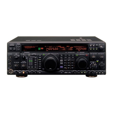
MAIN TUNING KNOB
This is the main frequency tuning dial for the
transceiver.
(16)ANALOG AND DIGITAL DISPLAYS
The analog display is calibrated every 50 kHz,
with 1 kHz marks providing finer resolution. The
digital display provides resolution to 100Hz.
(17) BAND
This switch selects the desired band
C
(l
8)
SELECT SWITCH
This switch selects the means of frequency control
for the transceiver. The details below apply tothe
fully equipped FT-107M (DMS unit installed).
TX EXT The transmit frequency is controlled
by the FV-107 extemal VFO
(option), while the receive frequency
is controlled
by
the
FT-107M
internal
VFO.
RX
EXT
The ieceive frequency is controlled by
the FV-107 external VFO (option),
while the transmit frequency is con-
trolled by the FT-107M internal VFO.
c
I
EXT The transceive frequency is controlled
by the FV-107 external VFO (option)
MR The transceive frequency is controlled
by the memory unit and/or the DMS
(Digital Memory Shift)control.
(19) PUSH SWITCHES (M,
M
SET, TX CLAR,
RX CLAR)
M Push the M button to store a fre-
quency
in
memory.
M
SFT Push this switch to activate the.
DMS system.
TX
CLAR While using the internal VFO or
RX
CLAR) memory,push the TX CLAR switch to
provide offset from the TX frequency.
Push the RX CLAR button to provide
offset of the receive frequency, and
push both buttons to provide offset
of the transceive frequency from the
dial frequency.
(20) CLARIFIER
The CLARIFIER allows offset from the VFO
or memory frequency, according to the selection
made by pushing the TX CLAR and/or RX CLAR
buttons.
(21)
M
FINE
This control allows fme tuning dunng memory
operation.
(22)
M
SET
This control activates the DMS system, allowing
offset tuning from a memory channel in 100 Hz
steps,
The
M
FINE control may, in
tum,
be used to
tune between the 100Hz steps.
(23)
M
CH
This control selects the desired memory channel.
(24) LEVER SWITCHES
PROC This switch activates the RF speech
processor.
ATT This switch activates a 20 dB attenu-
atorin the incoming signal path.


