Yaesu FT-60R User manual

VHF/UHF
DUAL BAND TRANSCEIVER
FT-60R
OPERATING MANUAL
VERTEX STANDARD CO., LTD.
4-8-8 Nakameguro, Meguro-Ku, Tokyo 153-8644, Japan
VERTEX STANDARD
US Headquarters
10900 Walker Street, Cypress, CA 90630, U.S.A.
YAESU EUROPE B.V.
P.O. Box 75525, 1118 ZN Schiphol, The Netherlands
YAESU UK LTD.
Unit 12, Sun Valley Business Park, Winnall Close
Winchester, Hampshire, SO23 0LB, U.K.
VERTEX STANDARD HK LTD.
Unit 5, 20/F., Seaview Centre, 139-141 Hoi Bun Road,
Kwun Tong, Kowloon, Hong Kong

Contents
Scanning .......................................................... 35
VFO Scanning .............................................. 35
Manual VFO Scan ................................... 35
Programmed VFO Scan ........................... 36
Memory Scanning ........................................ 37
How to Skip (Omit) a Channel
during Memory Scan Operation .............. 37
Preferential Memory Scan ....................... 38
Memory Bank Scan ................................. 39
Weather Alert Scan ...................................... 39
Programmable (Band Limit) Memory Scan
(PMS) ........................................................... 40
“Priority Channel” Scanning
(Dual Watch) ................................................ 41
Automatic Lamp Illumination
on Scan Stop ................................................ 43
Band Edge Beeper ........................................ 43
EPCS (
Enhanced Paging & Code Squelch
) ............. 44
Storing the CTCSS Tone Pairs
for EPCS Operation ..................................... 44
Activating the Enhanced Paging &
Code Squelch System .................................. 45
Paging Answer Back .................................... 45
Emergency Feature ........................................ 46
Emergency Channel Operation .................... 46
Emergency Automatic ID (EAI) Feature ..... 46
Smart Search Operation ................................ 48
Internet Connection Feature ......................... 49
ARTS
(Automatic Range Transponder System)
....... 51
DTMF Operation ........................................... 54
Miscellaneous Settings ................................... 56
Password ...................................................... 56
Programming the Key Assignment .............. 57
Changing the Channel Steps ........................ 57
Changing the Receiving Mode .................... 58
Receive Battery Saver Setup ........................ 59
TX Battery Saver .......................................... 59
Disabling the TX/BUSY Indicator .............. 60
Automatic Power-Off (APO) Feature .......... 60
Transmitter Time-Out Timer (TOT) ............ 61
Busy Channel Lock-Out (BCLO) ................ 61
Mono Band Operation ................................. 62
Changing the TX Deviation Level ............... 62
DCS Code Inversion .................................... 63
Reset Procedures ............................................ 64
Cloning ............................................................ 65
Set Mode .......................................................... 66
Specifications .................................................. 79
“AUTO” Mode Preset Operating Parameters
.... 80
General Description ......................................... 1
Accessories & Options ..................................... 2
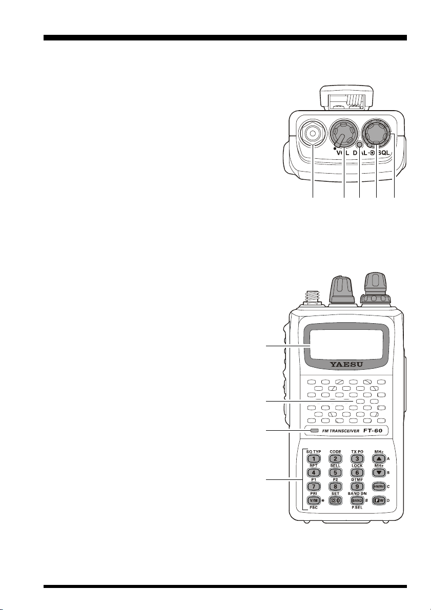
Controls & Connections .................................. 3
Top & Front Panel .......................................... 3
LCD ................................................................ 4
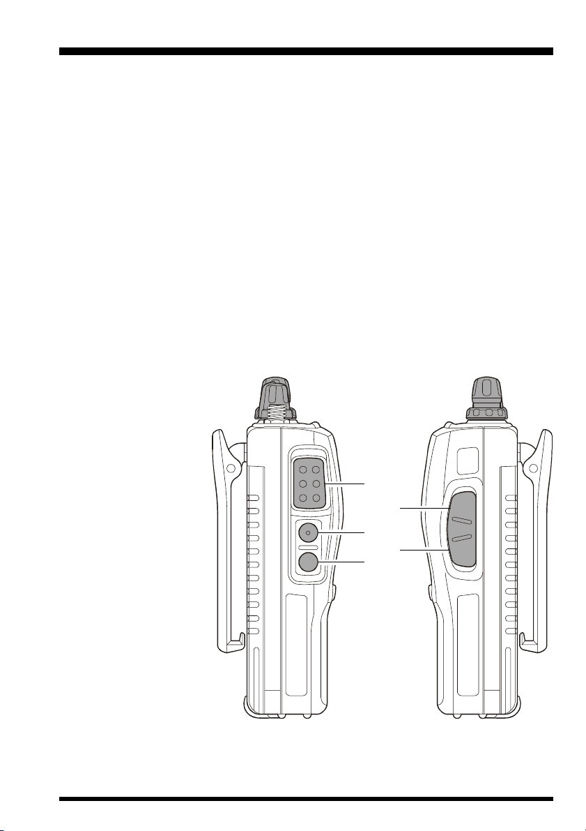
Side Panel ....................................................... 5
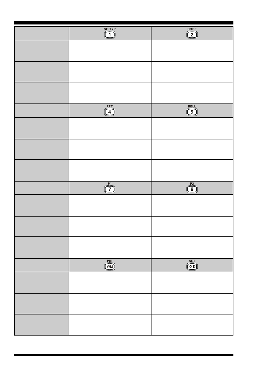
Keypad ........................................................... 6
Installation of Accessories ............................... 8
Antenna Installation ....................................... 8
Installation of FNB-83 Battery Pack ............. 8
Battery Charging ............................................ 9
Low Battery Indication ................................ 10
Installation of FBA-25A Battery Case ......... 10
Interface of Packet TNCs .............................. 11
Operation ........................................................ 12
Switching Power On and Off ....................... 12
Adjusting the Audio Volume Level and
Squelch Setting ....................................... 12
Selecting the Operating Band ...................... 13
Frequency Navigation .................................. 13
Transmission ................................................ 15
Advanced Operation ...................................... 16
Keyboard Locking ........................................ 16
Keypad/LCD Illumination ........................... 17
Disabling the Keypad Beeper ...................... 17
RF Squelch ................................................... 18
Checking the Battery Voltage ...................... 18
Repeater Operation ........................................ 19
Repeater Shifts ............................................. 19
Automatic Repeater Shift (ARS) ................. 19
Manual Repeater Shift Activation ............... 20
CTCSS/DCS Operation ................................. 22
CTCSS Operation ........................................ 22
DCS Operation ............................................. 23
Tone Search Scanning ................................. 24
CTCSS/DCS Bell Operation ........................ 25
Split Tone Operation .................................... 25
Tone Calling (1750 Hz) ............................... 26
Memory Mode ................................................ 28
Memory Storage ........................................... 28
Storing Independent
Transmit Frequencies (“Odd Split”) ........ 28
Memory Recall ............................................. 29
HOME Channel Memory ............................. 29
Labeling Memories ...................................... 30
Memory Offset Tuning ................................ 31
Deleting Memories ....................................... 32
Moving Memory Data to the VFO ............... 32
Memory Bank Operation ............................. 33
Memory Only Mode ..................................... 34
Weather Broadcast Channels ....................... 34

FT-60R OPERATING MANUAL 1
GENERAL DESCRIPTION
The FT-60R is a dual band FM transceiver with extensive receive frequency coverage,
providing local-area two-way amateur communications along with unmatched monitoring
capability.
The FT-60R’s small size allows you to take it anywhere - hiking, skiing, or while walking
around town - and its operating flexibility brings the user many avenues of operating en-
joyment. Its incredibly tiny FNB-83 Rechargeable Nickel-Metal Hydride Battery Pack
provides up to 5 Watts of transmit power on 144 MHz and 430 MHz Amateur Bands.
Besides 144- and 430-MHz transceive operation, the FT-60R provides receive coverage
of the VHF and UHF TV bands, the VHF AM aircraft band, and a wide range of commer-
cial and public safety frequencies!
New and exciting features of the FT-60R are the Emergency Automatic ID (EAI) function,
that will automatically cause your FT-60R to transmit your callsign and engage your rig’s
microphone, even if you are disabled and unable
to press the PTT switch; Enhanced Paging and
Code Squelch (EPCS), that allows you to page a
particular station and only receive calls from that
station, if desired; and a security Password fea-
ture, that will allow you to turn on and operate
your transceiver only after you enter your Pass-
word.
Additional features include a convenient access
key for Vertex Standard’s WIRES™ (Wide-cov-
erage Internet Repeater Enhancement System), a
transmit Time-Out Timer (TOT), Automatic
Power-Off (APO), Automatic Repeater Shift
(ARS), Yaesu’s exclusive ARTS™ (Auto-Range
Transponder System) which “beeps” the user when
you move out of communications range with an-
other ARTS™ equipped station, plus provision for
reduction of the TX deviation in areas of high chan-
nel congestion. And an RF squelch circuit allows
the owner to set the squelch to open at a program-
mable setting of the S-Meter, thus reducing guess-
work in setting the squelch threshold.
We appreciate your purchase of the FT-60R, and
encourage you to read this manual thoroughly, so
as to learn about the many exciting features of your
exciting new Yaesu hand-held transceiver!

FT-60R OPERATING MANUAL2
SUPPLIED ACCESSORIES
FNB-83 7.2 V, 1,400 mAh
Rechargeable Nickel-Metal Hydride Battery Pack
NC-88B/COvernight Battery Charger (10-Hour)
Belt Clip
Antenna
Operating Manual
Warranty Card
AVAILABLE OPTIONS
FNB-83 7.2 V, 1,400 mAh
Rechargeable Nickel-Metal Hydride Battery Pack
FBA-25A Compact Dry Battery Case for 6 AA-size cells
CD-29B/CRapid Charger (1.5-Hour)
NC-88B/COvernight Battery Charger (10-Hours)
CN-3 BNC-to-SMA Adapter
CT-27 Cloning Cable
CT-44 Microphone Adapter
E-DC-5B DC Cable with Cigarette-Lighter Adapter
E-DC-6 DC Cable; plug and wire only
MH-34B4B Speaker/Microphone
MH-37A4B Ear piece/Microphone
VC-25 VOX Headset
:“B” suffix is for use with 100-120 VAC, “C” suffix is for use with 230-240 VAC.
Availability of accessories may vary. Some accessories are supplied as standard per local
requirements, while others may be unavailable in some regions. Consult your Yaesu dealer
for details regarding these and any newly-available options. Connection of any non-Yaesu-
approved accessory, should it cause damage, may void the Limited Warranty on this ap-
paratus.
ACCESSORIES & OPTIONS

FT-60R OPERATING MANUAL 3
CONTROL & CONNECTIONS (TOP & FRONT PANEL)
Antenna Jack
Connect the supplied rubber flex antenna (or another antenna presenting a 50-Ohm
impedance) here.
VOL/PWR Knob
Turn this control clockwise to turn the radio on and to
increase the volume. Counter-clockwise rotation into
the click-stop will turn the radio off.
TX/BUSY Indicator Lamp
This indicator glows green when the squelch opens,
and turns red during transmit.
DIAL Knob
This (inner) 20-position detented rotary switch is used for setting the operating fre-
quency, and also is used for menu selections and other adjustments.
SQL Knob
This (outer) control is used to silence back-
ground noise on the receiver. It should be ad-
vanced clockwise just to the point where the
noise is silenced (and the green “BUSY” indi-
cator turns off).
LCD (Liquid Crystal Display)
The display shows current operating condition,
as indicated on the next page.
Speaker
The internal speaker is located here.
Microphone
The internal microphone is located here.
Keypad
These 16 keys select many of most important
operating features on the FT-60R. The func-
tions of the keys are described in detail on the
pages to follow.

FT-60R OPERATING MANUAL4
CONTROL & CONNECTIONS (LCD)
Operating Frequency
Memory Channel Number
S- & PO Meter
Secondary Keypad
Active
Skip Memory Channel
or Preferential Memory
Channel
Repeater Shift Direction
CTCSS/DSC Operation
Internet Connection
Feature Active
Key Lock Active
Operating Mode
Bell Alerm Active
Battery Saver Active
Dual Watch Active
Priority Channel
Automatic Power-Off
Active
Battery Indicator
Memory Bank Active
Low TX Power Selected

FT-60R OPERATING MANUAL 5
PTT (Push To Talk) Switch
Press this switch to transmit, and release it (to receive) after your transmission is com-
pleted.
MONI Switch
Pressing this switch disables the noise squelching action, allowing you to hear very
weak signals near the background noise level temporarily.
Press the [F/W]key on the keypad first, then press this switch to “open” the squelch
continuously. Press this switch again to resume normal (quiet) monitoring.
LAMP Switch
Pressing this switch illuminates the LCD and keypad for five seconds, after which the
back-lighting will automatically turn off.
Press the [F/W]key on the keypad first, then press this switch to activate the back-
lighting lamp continuously. To turn the lamp off, press this switch again.
You can change the primary (press key) function of this switch, if you prefer. See page
17 for details.
MIC/SP Jack
This four-conductor
miniature jack pro-
vides connection
points for microphone
audio, earphone au-
dio, PTT, and ground.
EXT DC Jack
This coaxial DC jack
allows connection to
an external DC power
source (6-16V DC).
The center pin of this
jack is the Positive (+)
connection.
MIC
/SP
EXT
DC
CONTROL & CONNECTIONS (SIDE PANEL)

FT-60R OPERATING MANUAL6
CONTROL & CONNECTIONS (KEYPAD)
Third Function
(PRESS & HOLD KEY)
Secondary Function
(PRESS [F/W]+ KEY)
Primary Function
(PRESS KEY)
Third Function
(PRESS & HOLD KEY)
Secondary Function
(PRESS [F/W]+ KEY)
Primary Function
(PRESS KEY)
Third Function
(PRESS & HOLD KEY)
Secondary Function
(PRESS [F/W]+ KEY)
Primary Function
(PRESS KEY)
Third Function
(PRESS & HOLD KEY)
Secondary Function
(PRESS [F/W]+ KEY)
Primary Function
(PRESS KEY)
Frequency entry digit “1”
Activates the CTCSS or DCS
Operation
Recalls the “Weather” broadcast
channel bank
Frequency entry digit “2”
Selects the CTCSS tone or DCS
code number
Activates the ARTS feature
Frequency entry digit “4”
Selects the direction of the uplink
frequency shift (either “–,” “+,” or
“simplex”) during repeater operation
Activates the EMERGENCY
function
Frequency entry digit “5”
Selects the CTCSS/DCS Bell ringer
repetitions
None
Frequency entry digit “7”
None None
Activates the EPCS (Enhanced
Paging & Code Squelch) feature
Frequency entry digit “8”
Selects the Memory Scan “Skip”
channel-selection mode
Switches the frequency control
between the VFO and Memory
Systems
Activates the Priority (Dual Watch)
function
Starts the programmable scanner
upward (toward a higher frequency
or a higher channel number)
Activates the Internet Connection
feature
Frequency entry digit “0”
Engages the Set (Menu) Mode
Enables Internet access code
selection
1: You can program the secondary (press [F/W]key +) function of the key to another function, if
desired. See page 57 for details.
11

FT-60R OPERATING MANUAL 7
CONTROL & CONNECTIONS (KEYPAD)
Third Function
(PRESS & HOLD KEY)
Secondary Function
(PRESS [F/W]+ KEY)
Primary Function
(PRESS KEY)
Third Function
(PRESS & HOLD KEY)
Secondary Function
(PRESS [F/W]+ KEY)
Primary Function
(PRESS KEY)
Third Function
(PRESS & HOLD KEY)
Secondary Function
(PRESS [F/W]+ KEY)
Primary Function
(PRESS KEY)
Third Function
(PRESS & HOLD KEY)
Secondary Function
(PRESS [F/W]+ KEY)
Primary Function
(PRESS KEY)
Frequency entry digit “3”
Selects the desired transmit power
output level
Activates the Smart Search feature
Increases the VFO frequency by
one step or moves the memory
channel to the next-highest channel
Tunes the VFO frequency upward
in 1 MHz steps
Starts the scanner upward
(toward a higher frequency or
a higher channel number)
Frequency entry digit “6”
Activates the Key Lockout feature
Decreases the VFO frequency by
one step or moves the memory
channel to the next-lowest channel
Tunes the VFO frequency down-
ward in 1 MHz steps
Starts the scanner downward
(toward a lower frequency or a
lower channel number)
Frequency entry digit “9”
Selects the DTMF mode
Reverses the transmit and receive
frequencies while working through
a repeater
Switches to the “Home” (favorite
frequency) Channel
None None
Moves operation to the next-
highest frequency band while in the
VFO mode
Activates the “Memory “Tune” mode
while in the Memory Recall mode
Moves operation to the next-lowest frequency band
Selects the bandwidth for the
programmable scanner while in the
VFO mode
Activates the “Secondary” key
function
Disables the “Secondary” key
function
Activates the “Memory Write” mode
(for memory channel storage)
2: You can exchange the function between primary (press key) function and secondary (press [F/W]
key +) function, if desired. See page 74 for details.
2

FT-60R OPERATING MANUAL8
ANTENNA INSTALLATION
The supplied antenna provides good results over the entire fre-
quency range of the transceiver. However, for enhanced recep-
tion on certain non-Amateur frequencies, you may wish to con-
nect an antenna designed specifically for that frequency range,
as the supplied antenna is necessarily a compromise outside the
Amateur bands, and cannot be expected to provide high perfor-
mance at all frequencies.
To install the supplied antenna, hold the bottom end of the an-
tenna, then screw it onto the mating connector on the transceiver
until it is snug. Do not over-tighten by use of extreme force.
Notes:
Never transmit without having an antenna connected.
When installing the supplied antenna, never hold the upper part of the antenna while
screwing it onto the mating connector on the transceiver.
If using an external antenna for transmission, ensure that the SWR presented to the
transceiver is 1.5:1 or lower, to avoid excessive feedline loss.
INSTALLATION OF FNB-83 BATTERY PACK
The FNB-83 is a high-performance Ni-MH battery providing high capacity in a compact
package. Under normal use, the FNB-83 may be used for approximately 300 charge cycles,
after which operating time may be expected to decrease. If you have an old battery pack
which is displaying capacity which has become diminished, you should replace the pack
with a new one.
Installation of the battery is easy and quick:
Insert the battery pack into the battery compartment on the back of the
radio while tilting the Belt Clip outward, then close the
Battery Pack Latch until it locks in place
with a “Click.”
To remove the
battery, turn the
radio off and re-
move any pro-
tective cases.
Open the Bat-
tery Pack Latch
on the bottom of the radio, then slide the battery downward and out from the radio
while tilting the Belt Clip out of the way.
INSTALLATION OF ACCESSORIES
Install the Battery Pack
Close the Battery Pack Latch
MIC
/SP
EXT
DC

FT-60R OPERATING MANUAL 9
BATTERY CHARGING
If the battery has never been used, or its charge is depleted, it may be charged by connect-
ing the NC-88 Overnight Battery Charger, as shown in the illustration, to the EXT DC
jack. If only 12 ~ 16 Volt DC power is available, the optional E-DC-5B DC Adapter (with
its cigarette lighter plug) may also be used for charging the battery.
A fully-discharged pack will be charged completely in 10 hours. Disconnect the NC-88
from the EXT DC jack and the AC line outlet.
Important Note
The NC-88 is not designed to power the transceiver for operation (reception or
transmission).
Do not leave the NC-88 connected to the transceiver for continuous periods in ex-
cess of 24 hours. Long term overcharging can degrade the Ni-MH battery pack and
significantly shorten its useful life.
Please be advised that the NC-88 may contribute noise to TV and radio reception in
the immediate vicinity, so we do not recommend its use adjacent to such devices.
INSTALLATION OF ACCESSORIES
EXT DC jack
AC line outlet

FT-60R OPERATING MANUAL10
LOW BATTERY INDICATION
As your battery discharges during use, the voltage will gradually become lower. When
the battery voltage is becoming too low for reliable operation,
the “ ” icon will blink on the LCD display, indicating that the
battery pack must be recharged before further use.
Avoid recharging Ni-MH batteries before the “ ” indicator is observed, as this can
degrade the charge capacity of your Ni-MH battery pack.
INSTALLATION OF FBA-25A ALKALINE BATTERY CASE (OPTION)
The optional FBA-25A Battery Case allows operation of the FT-60R using six “AA” size
Alkaline batteries.
When installing batteries, insert the (–) end first, then press in the (+) end so the battery
snaps into place. Always replace all six batteries at the same time, paying attention to the
polarity indicated inside the case.
The FBA-25A must not be used with rechargeable cells. The FBA-25A does not contain
the thermal and over-current protection circuits (provided in the “FNB” series of Ni-MH
Battery Packs) required when utilizing Ni-Cd and Ni-MH cells.
Note that the power output and battery life will be much shorter when using Alkaline AA
cells. They should be considered an emergency backup power source only, for this rea-
son.
INSTALLATION OF ACCESSORIES

FT-60R OPERATING MANUAL 11
The FT-60R may be used for Packet operation, using the optional CT-44 microphone
adapter (available from your Yaesu dealer) for easy interconnection to commonly-avail-
able connectors wired to your TNC. You may also build your own cable, using a four-
conductor miniature phone plug, per the diagram below.
The audio level from the receiver to the TNC may be adjusted by using the VOL knob, as
with voice operation. The input level to the FT-60R from the TNC should be adjusted at
the TNC side; the optimum input voltage is approximately 5 mV at 2000 Ohms.
Be sure to turn the transceiver and TNC off before connecting the cables, so as to prevent
voltage spikes from possibly damaging your transceiver.
When you are operating on Packet, switch the Receive Battery Saver OFF, as the “sleep”
cycle may “collide” with the beginning of an incoming Packet transmission, causing your
TNC not to receive the full data burst. See page 59 for details regarding Battery Saver
setup.
INTERFACE OF PACKET TNCS
CT-44
EAR
MIC
10µF
2 kΩ
+
SP
GND
GND
MIC
PTT
TNC
MIC/SP

FT-60R OPERATING MANUAL12
Hi! I’m R. F. Radio, and I’ll be helping you along as you learn the many
features of the FT-60R. I know you’re anxious to get on the air, but I encour-
age you to read the “Operation” section of this manual as thoroughly as
possible, so you’ll get the most out of this fantastic new transceiver. Now. . .let’s get
operating!
SWITCHING POWER ONAND OFF
Be sure the Battery Pack is installed, and that the bat-
tery is fully charged. Connect the antenna to the top panel
Antenna jack.
Rotate the top panel’s VOL knob out of the click-stop to
turn on the radio. The current DC supply voltage will be
indicated on the display for 2 seconds. After this 2 sec-
ond interval, the display will resume its normal indica-
tion of the operating frequency.
To turn the radio off, turn the VOL knob fully counter-clockwise into the click stop
position.
ADJUSTING THE AUDIO VOLUME LEVEL AND SQUELCH SETTING
At first, set the SQL knob fully counter-clockwise. Now,
you may rotate the VOL knob to adjust the receiver level
for a comfortable listing level, using the background
noise as a reference.
To set the squelch, turn the SQL knob clockwise, slightly
past the point where the background noise is muted. This
is the point of best sensitivity to weak signals, and we
recommend that you not rotate the SQL knob very much past the point where the
background noise is just silenced.
1) A special “RF Squelch” feature is provided on this radio. This feature
allows you to set the squelch so that only signals exceeding a certain S-meter
level will open the squelch. See page 18 for details.
2) If you’re operating in an area of high RF pollution, you may need to consider “Tone
Squelch” operation using the built-in CTCSS Decoder. This feature will keep your ra-
dio quiet until a call is received from a station sending a carrier which contains a matching
(subaudible) CTCSS tone. Or, if your friends have radios equipped with DCS (Digital
Coded Squelch) like your FT-60R has, try using that mode for silent monitoring of busy
channels.
OPERATION

FT-60R OPERATING MANUAL 13
OPERATION
SELECTING THE OPERATING BAND
Press the [BAND(BAND DN)] key repetitively. You will
see the LCD indication move toward a higher frequency
band each time you press the [BAND(BAND DN)] key.
850 MHz 144 MHz
250 MHz 350 MHz
430 MHz 850 MHz ……
If you wish to move the operating band selection down-
ward (toward a lower frequency band), press the [F/W]
key first, then press the [BAND(BAND DN)] key.
350 MHz 250 MHz
144 MHz 850 MHz
430 MHz 350 MHz ……
Once you have selected the desired band, you
may initiate manual tuning (or scanning) per
the discussion in the next chapter.
FREQUENCY NAVIGATION
The FT-60R will initially be operating in the “VFO” mode, a channelized system which
allows free tuning throughout the currently-selected operating band.
Three basic frequency navigation methods are available on the FT-60R:
1)Tuning Dial
Rotation of the DIAL allows tuning in the pre-programmed
steps established for the current operating band. Clockwise
rotation of the DIAL causes the FT-60R to be tuned toward
a higher frequency, while counter-clockwise rotation will
lower the operating frequency.
If you press the [F/W]key momentarily, then rotate the DIAL,
frequency steps of 1 MHz will be selected. This feature is
extremely useful for making rapid frequency excursions over the wide tuning range of the
FT-60R.
FREQUENCY RANGE
108.000 - 200.000 MHz
200.000 - 300.000 MHz
300.000 - 400.000 MHz
400.000 - 520.000 MHz
700.000 - 999.990 MHz
BAND
144 MHz Band
250 MHz Band
350 MHz Band
430 MHz Band
850 MHz Band

FT-60R OPERATING MANUAL14
2)Direct Keypad Frequency Entry
The desired operating frequency may be entered directly from the keypad.
To enter a frequency from the keypad, just press the numbered digits on the keypad in the
proper sequence.
Examples:
To enter 146.560 MHz, press [1][4][6][5][6][0]
To enter 146.5625 MHz (in 12.5 kHz), [1][4][6][5][6][2]
3)Scanning
Press and hold in either the [(MHz)] or [(MHz)] key
for one second to initiate upward or downward scanning,
respectively (Manual VFO Scan).
For scanning within a limited sub-band range, from the VFO
mode, press and hold in the [V/M(PRI)] key for one second
to begin scanning toward a higher frequency within the pre-
viously-defined sub-band (Programmed VFO Scan). Details
regarding sub-band setup may be found on page 36.
If you wish to reverse the direction of the scan (i.e. toward a
lower frequency, instead of a higher frequency), just rotate
the DIAL one click in the counter-clockwise direction while
the FT-60R is scanning. The scanning direction will be re-
versed. To revert to scanning toward a higher frequency once
more, rotate the DIAL one click clockwise.
The scanner will stop when it receives a signal strong enough to break through the Squelch
threshold. The FT-60R will then hold on that frequency according to the setting of the
“RESUME” mode (Set Mode Item 34: RESUME). Press the PTT switch momentarily to
cancel the scanning. This only stops the scan; it does not cause transmission to occur. See
page 35 for details regarding Scan Operation.
OPERATION
FREQUENCY NAVIGATION
(Programmed VFO Scan)
(Manual VFO Scan)

FT-60R OPERATING MANUAL 15
TRANSMISSION
Once you have set up an appropriate frequency inside one of the 144 MHz or 430 MHz
Amateur bands on which the FT-60R can transmit, you’re ready to go on the air! These are
the most basic steps; more advanced aspects of transmitter operation will be discussed later.
To transmit, press the PTT switch, and speak into the
front panel microphone (located in the lower left-hand
corner of the speaker grille) in a normal voice level. The
TX/BUSY indicator will glow red during transmission.
To return to the receive mode, release the PTT switch.
During transmission, the relative power level will be
indicated on the bar graph at the bottom of the LCD;
full scale deflection confirms “High Power” operation, while deflection of two bars
indicates “Low Power” operation. Five bars indicates “Medium Power” operation.
Additionally, the “LOW” icon will appear at the bottom of the display while operating
on the “Low Power” and “Medium Power” settings.
1) If you’re just talking to friends in the immediate area, you’ll get much longer
battery life by switching to Low Power operation, described in the next chapter.
And don’t forget: always have an antenna connected when you transmit.
2) Transmission is possible only on the 144 MHz and 430 MHz bands.
Changing the Transmitter Power Level
To change the power level:
Press the [F/W]key, then press the [3(TX PO)] key.
The LCD shows the current power output level.
Rotate the DIAL knob to select the desired power out-
put level. Available selections are “HIGH” (5 W), “MID”
(2 W), and “LOW” (0.5 W).
When you have made your choice, press the PTT switch
to save the new setting and return to normal operation.
1) The FT-60R is smart! You can set up Low power on the 144 MHz band,
while leaving 430 MHz on High power, and the radio will remember the
different settings on both bands. And when you store memories, you can store
the power output settings separately in each memory, so you don’t waste battery power
when using very close-in repeaters!
2) When you are operating on the “Low” or “Medium” power setting, you can press the
[F/W] key, when press the PTT switch, to cause the FT-60R to transmit (temporarily) on
High power. After one transmission, the power level will revert to the previously-selected
(“Low” or “Medium” power) setting.
OPERATION

FT-60R OPERATING MANUAL16
Now that you’re mastered the basics of FT-60R operation, let’s learn more about some of
the really neat features.
KEYBOARD LOCKING
In order to prevent accidental frequency change or inadvertent transmission, various as-
pects of the FT-60R’s DIAL and keypad may be locked out. The possible lockout combi-
nations are:
LK KEY: Just the front panel keypad is locked out
LKDIAL: Just the top panel DIAL is locked out
LK K+D: Both the keypad and DIAL are locked out (factory default)
LK PTT: The PTT switch is locked out (TX not possible)
LK P+K: Both the PTT switch and keypad are locked out
LK P+D: Both the PTT switch and DIAL are locked out
LK ALL: All of the above are locked out
To lock out some or all of the keys:
1. Press the [F/W]key, then press the [0( )SET]key to enter the Set mode.
2. Rotate the DIAL knob to select Set Mode Item 25: LOCK.
3. Press the [F/W]key momentarily to enable adjustment of this
Item.
4. Rotate the DIAL knob to choose between one of the locking
schemes as outlined above.
5. When you have made your selection, press the PTT switch to
save the new setting and return to normal operation.
To activate the locking feature, (1) press and hold in the
[6(LOCK)] key for one second, or (2) press the [F/W]key,
then press the [6(LOCK)] key. The “ ” icon will appear on
the LCD. To cancel locking, repeat this process.
ADVANCED OPERATION

FT-60R OPERATING MANUAL 17
ADVANCED OPERATION
KEYPAD/LCD ILLUMINATION
Your FT-60R includes a reddish illumination lamp which aids in nighttime operation. The
reddish illumination yields clear viewing of the display in a dark environment, with mini-
mal degradation of your night vision.
Three options for activating the lamp are provided:
KEY Mode: Illuminates the Keypad/LCD lamp for five seconds when you rotate
the DIAL knob or press the keypad or any switch (except PTT switch).
This is the factory-programmed default setting.
5SEC Mode: Illuminates the Keypad/LCD lamp for five seconds when you press
the LAMP switch momentarily.
TOGGLE Mode: Toggles the Keypad/LCD lamp on and off when you press the LAMP
switch momentarily.
Here is the procedure for setting up the Lamp operating mode:
1. Press the [F/W]key, then press the [0( )SET]key to enter the Set mode.
2. Rotate the DIAL knob to select Set Mode Item 24: LAMP.
3. Press the [F/W]key momentarily to enable adjustment of this
Item.
4. Rotate the DIAL knob to select one of the three modes described
above.
5. When you have made your choice, press the PTT switch to save
the new setting and return to normal operation.
Press the [F/W] key first, then press the LAMP switch to illuminate the Key-
pad/LCD lamp continuously until you press the LAMP key again, irrespec-
tive of the Lamp mode programmed per the above instructions.
DISABLING THE KEYPAD BEEPER
A keypad beeper provides useful audible feed back whenever a keypad is pressed.
If you want to turn the beep off:
1. Press the [F/W]key, then press the [0( )SET]key to enter the Set mode.
2. Rotate the DIAL knob to select Set Mode Item 6: BEEP.
3. Press the [F/W]key momentarily to enable adjustment of this
Item.
4. Rotate the DIAL knob to change the setting to “OFF.”
5. Press the PTT switch to save the new setting and return to nor-
mal operation.
6. To turn the beep back on again, select “KEY” or “KEY+SC (factory default)” in step 4
above.
KEY: The beeper sounds when you press the keypad.
KEY+SC: The beeper sounds when you press the keypad, or when the scanner stops.

FT-60R OPERATING MANUAL18
RF SQUELCH
A special RF Squelch feature is provided on this radio. This feature allows you to set the
squelch so that only signals exceeding a certain S-meter level will open the squelch.
To set up the RF squelch circuit for operation, use the following procedure:
1. Press the [F/W]key, then press the [0( )SET]key to enter the Set mode.
2. Rotate the DIAL knob to select Set Mode Item 37: RF SQL.
3. Press the [F/W]key momentarily to enable adjustment of this
Item.
4. Rotate the DIAL knob to select the desired signal strength level
for the squelch threshold (S-1, S-2, S-3, S-4, S-5, S-6, S-8, S-
FULL, or OFF).
5. Press the PTT switch to save the new setting and return to normal operation.
6. Finally, rotate the SQL knob fully clockwise.
CHECKING THE BATTERY VOLTAGE
The FT-60R’s microprocessor includes programming which will measure the current bat-
tery voltage.
1. Press the [F/W]key, then press the [0( )SET]key to enter the Set mode.
2. Rotate the DIAL knob to select Set Mode Item 12: DC VLT.
3. Press the [F/W]key momentarily to display the current DC volt-
age being supplied.
4. Press the PTT switch to return to normal operation.
ADVANCED OPERATION
Other manuals for FT-60R
7
Table of contents
Other Yaesu Transceiver manuals

Yaesu
Yaesu FT-710 User manual

Yaesu
Yaesu FT-2400H User manual

Yaesu
Yaesu VX-120 Series Manual

Yaesu
Yaesu VX-8DR User manual

Yaesu
Yaesu VX-8DE User manual

Yaesu
Yaesu CPU-2500R User manual

Yaesu
Yaesu FT-65R User manual

Yaesu
Yaesu FT-2000 - MENU MODE LIST Product guide

Yaesu
Yaesu FTC-4610 Manual

Yaesu
Yaesu FTM-3100R User manual