(Page)
FOREWORD)
26
cic acu ese
toccevnee
vse
stire
deaveia
¢
S'S
Hee
EW
BORER
PELs
ois
Sra
wieta
as
trace
Ne’
s
sieIe
ie
ial
i
SECTION
1
—
GENERAL
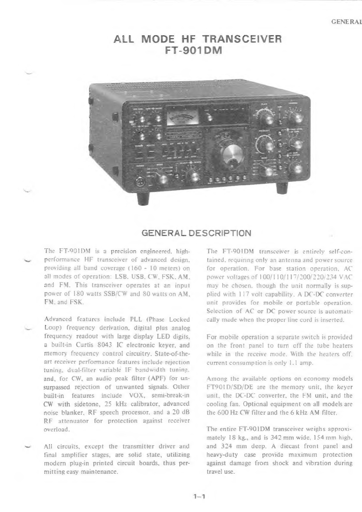
GENERAL
DESCRIPTION:
«
52
o15
6:60:50
0:6
sisyoese
etre
ssoeieie
ue
welpinin
tee
eee
ee
Ee
HHS
1-1
SPECIFICATIONS
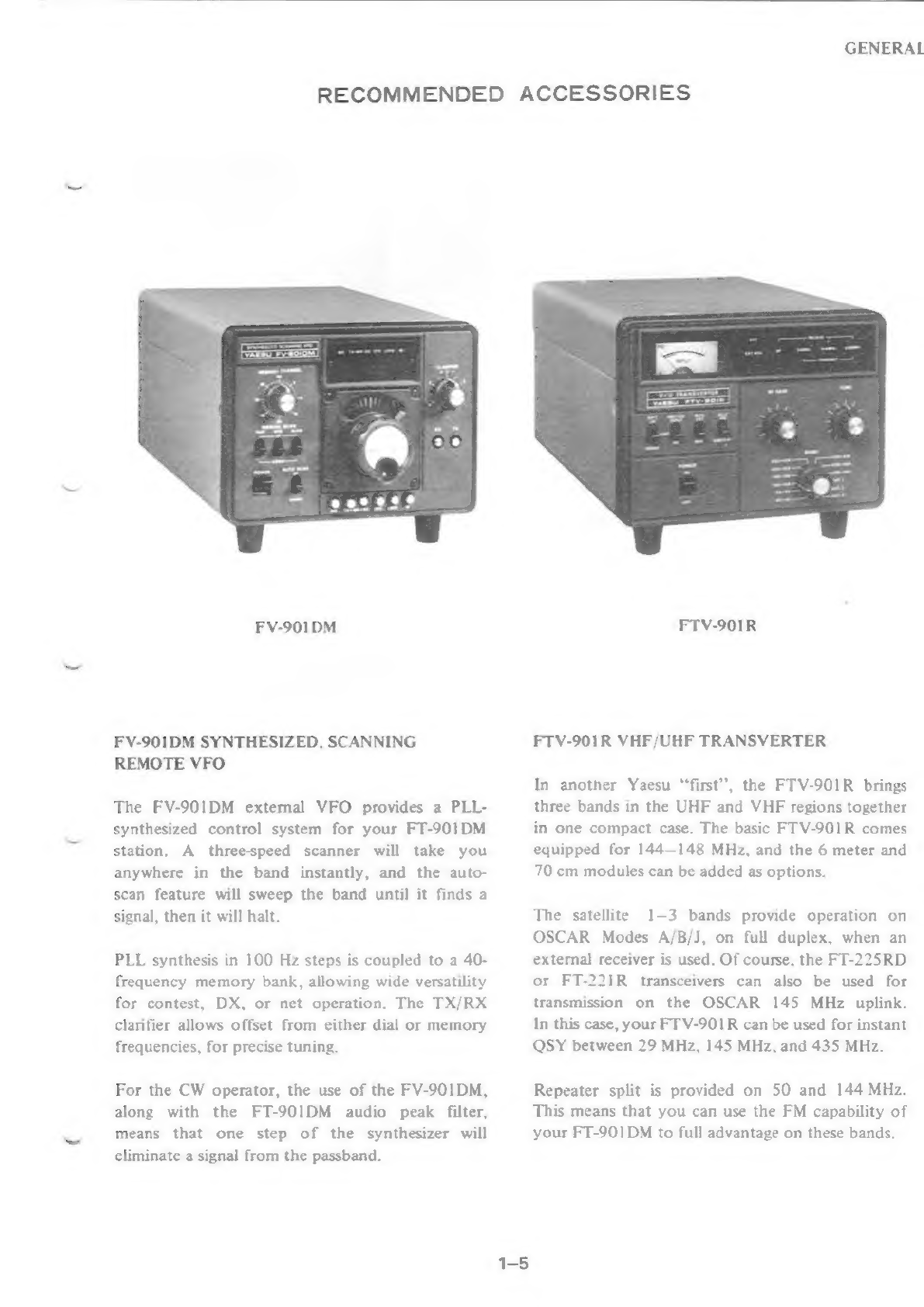
RECOMMENDED
ACCESSORIES
CONTROLS
AND
SWITCHES
..........
2220s
eee
e
cece
cere
cere
e
teen
eee
e
eee
eeeneee
REAR
APRON
CONNECTIONS
...........---
2c
eee
reece
eet
eee
e
eee
e
eee
eees
INTERCONNECTION
DIAGRAMS
INSTALLATION
(0):
150.
U1
(9),
pa
Se
caer
ee
eI
MICROPHONE
CONNECTIONS
SECTION
2
—
TECHNICAL
NOTES
PARTS
DESIGNATIONS
ON
CIRCUIT
BOARDS
SIGNAL
TRACING
IN
THE
FT-901
........-..2.
0s
eee
cece
erect
ete
eee
e
eee
eee
d
AUGMENTED
BLOCK
DIAGRAMS
...........-00
0
eee
ee
rere
eter
e
reer
eee
e
ee
eennees
2-3
FREQUENCY
RELATIONS/CRYSTAL
DATA
......
0.0000
e
cree sere
erent
eee
e
nee
2-10
THEORY
OF
OPERATION
Ht
9.20)
3
0,
OM
y
(0)
FRONT
PANEL
REMOVAL
INSTALLATION
OF
ACCESSORIES
KEYER/MEMORY
UNITS
........
20.0.0
0
ees
ce
eect
eee
e
eee
e
eee
e
eee
eee
eees
3-4
AM/GW.
BILTERS):.
ijcc5:050
5
25
srafee
2260.04
bo or
20s
aie
Keates
Wa
wshelas
arediaie
ia
wha
epee
3-5
DC-DC
CONVERTER
...
2.2...
cece
cee
cece
cette renee
e
eee
e
nee
n
nese
ses
enens
3-6
FM
UNIT
COOLING
FAN
SOLDERING
AND
DESOLDERING
TECHNIQUE
3-10
CIRCUIT
TRACE
REPAIR
...
2.2...
52
20
cc
cece
cence
eee
eee
cee nee
eeeas
3-11
MODIFICATIONS
VFO
DRIFT
IN
PRESENCE
OF
NEARBY
VHF
TRANSMITTER............+-+++
3-13
MEMORY
UNIT
HUM,
MR
MODE
............06
25
eee
cee
eee
eee
teenies
3-14
COUNTER
UNIT
CAPACITOR
REVERSAL
. :
3
3-15
POWER
SUPPLY
PROTECTION
.........-
2220020
cece
ne
cent
teen
e
eee
ne
nee
ee
neers
3-16
KEY
CLICK:
MODIFICATION
i.
i::esoie
35
6
oceb5-
tue
dinvesasernie
tye
diarere
ere
erisiore
ecb
rei
nige
nek
le
3-17
RECTIFIER
C
UNIT
MODIFICATION
...........
02
e
cece
eee
e
eee
eee
e
eens
3-17
WWV/JJY
FREQUENCY
CHANGE...
..........5
22-2
e
eee
eee
cece
cece
cece
eee
ee
3-18
MOSFET
CHANGES..........-
2
RF
PROCESSOR/XTAL
UNIT
TRANSISTOR
CHANGE
...........-.-22.0+22005-
3-20