IRT DTR-4630 User manual

DTR-4630
I.R.
T.
Communications
Pty
L
t
d
|
www
.i
rtcommunication
s.
c
o
m
Revision 02
3G/HD/ D- DI/A I Fibre Optic Transceiver
User Manual

DTR-4630
I.R.
T.
Communications
Pty
L
t
d
|
www
.i
rtcommunication
s.
c
o
m
Page 2 of 17
Revision 02
3G/HD/SD-SDI/ASI FIBRE OPTIC TRANSCEI ER
Revision History:
Revision Date By Change Description Applicable to:
00 06/05/2013 AL Original Issue.
Units fitted with
firmware version ≥
Dxx463x 1V1
01 19/06/2013 AL Alarm conditions and NMP MIB descriptors
corrected.
Units fitted with
firmware version ≥
Dxx463x 1V3
02 19/01/2016 AL Upgraded to I.R.T. Communications company name.
Units fitted with
firmware version ≥
Dxx463x 1V3

DTR-4630
I.R.
T.
Communications
Pty
L
t
d
|
www
.i
rtcommunication
s.
c
o
m
Page 3 of 17
Revision 02
USER MANUAL
Table of Contents:
Section Page
Revision History 2
Operational afety 4
General Description 5
Technical pecifications 6
Configuration 7
User DIP switch and link settings 7
Installation 8
ignal Connections 8
Optical Connections 9
Alarm Connections 9
Front and rear layouts 10
Operation 11
Figure 1: Attenuation versus wavelength 12
Front Panel LED Indicators 12
D only, HD/ D only modes 12
NMP – What Is It? 13
DTR-4630 NMP Functions 15
Maintenance & torage 17
Warranty & ervice 17
This instruction book applies to units fitted with firmware version ≥ Dxx463x 1V3.

DTR-4630
I.R.
T.
Communications
Pty
L
t
d
|
www
.i
rtcommunication
s.
c
o
m
Page 4 of 17
Revision 02
OPERATIONAL SAFETY
WARNING
Operation of electronic equipment involves the use of voltages and currents that
may be dangerous to human life. Note that under certain conditions dangerous
potentials may exist in some circuits when power controls are in the OFF position.
Maintenance personnel should observe all safety regulations.
Do not make any adjustments inside equipment with power ON unless proper
precautions are observed. All internal adjustments should only be made by suitably
qualified personnel. All operational adjustments are available externally without
the need for removing covers or use of extender cards.
Optical Safety
The light emitted from the LA ER diode used in this system is
invisible and may be harmful to the human eye. Avoid looking
directly into the fibre optic cable or connectors or into the
collimated beam along their axis when the device is in operation.
Operating the LA ER diode outside of its maximum ratings may
cause device failure or a safety hazard.
DANGER
Avoid direct exposure to beam
Peak power 2 mW
Wavelength 1270–1610nm
Class 1 LASER Product
Invisible LASER radiation-

DTR-4630
I.R.
T.
Communications
Pty
L
t
d
|
www
.i
rtcommunication
s.
c
o
m
Page 5 of 17
Revision 02
GENERAL DESCRIPTION
The IRT DTR-4630 is a transmit/receive (transceiver) module designed principally for use as a serial data fibre optic
transmission link for 3G- DI, HD- DI or D- DI applications conforming to MPTE standards 424M, 292M and 259M-C
using 9/125 μm single mode fibre. This enables the use of space saving fibre optic cable for reliable transmission of
digital video signals over lengths greater than can be achieved with coaxial cable.
In addition, the link may be used for A I transport streams for use with MPEG compressed video streams or other
270 Mb/s type data.
The transmitter section features automatic input cable equalisation. LED indicators are provided for digital signal
presence and rate, DC power and LA ER failure.
A “keep link alive” signal is available to maintain optical link operation when no electrical input is present.
Two inputs are provided with automatic changeover to input 2 on loss of input 1 for input signal redundancy.
The receiver section uses a choice of either a PIN photodiode or APD detector with signal conditioning and reclocking
circuits. The data rate is automatically set to match the 3G- DI, HD- DI or D- DI/A I rates dependent on the actual input
data rate to the transmitter.
Two serial digital outputs are provided. LED indicators are provided for digital signal presence & type, optical loss and
power.
Relay contact outputs are also provided for external use of alarm signals.
The DTR-4630 can be used as an independent transmitter and receiver at the same time allowing bi-directional
operation over two single mode fibres. Being independent from each other, the transmit and receive signals can be of
mixed signal types.
Optionally a 1310/1550nm WDM
2, 3
optical combiner can be fitted to allow for combined use on a single fibre.
NMP ( imple Network Management Protocol) is available for remote monitoring when used in conjunction with an IRT
frame fitted with NMP capability.
Standard features:
•
Transports 3G-SDI, HD-SDI, SD-SDI or ASI signal rates.
•
Single or bi-directional operation possible with independent transmit and receive functions on the one card
.
•
Path lengths up to 30 dB
1
optical path loss using 9/125μm single mode fibre
.
•
Automatic changeover switching of input for signal redundancy on Tx.
•
LED indicators and external alarm contacts
.
•
Fibre, video and alarm connections at rear
.
•
Remote monitoring via SNMP.
•
Optional on-board WDM
2, 3
optical combiner for use on a single common fibre
.
NOTE: 1 27dB path loss at 3G. Typically >30dB at HD and D. Fitted with APD detector.
2 With WDM option fitted for combined use on a single fibre, optical path loss is reduced by approximately 2dB.
3 With WDM option fitted, when operating as a pair, one DTR-4630 must be fitted with a 1310nm laser and
the other a 1550nm laser.
BLOCK DIAGRAM DTR -4630 SIGNAL PATH
Fibre Link
9-27
*
dB path loss at 3G
(>30dB at HD and D)
NOTE: * Fitted with APD detector. 3-18dB when fitted with PIN detector.
DTR-4630
(Tx/Rx)
I/P 1
I/P 2
Fibre O/P
Fibre I/P
O/P 1
O/P 2
Alarm O/P
DTR-4630
(Tx/Rx)
O/P 1
O/P 2
Fibre I/P
Fibre O/P
I/P 1
I/P 2
Alarm O/P
NMP NMP
3G- DI
HD- DI
D- DI
A I
3G- DI
HD- DI
D- DI
A I
3G- DI
HD- DI
D- DI
A I
3G- DI
HD- DI
D- DI
A I

DTR-4630
I.R.
T.
Communications
Pty
L
t
d
|
www
.i
rtcommunication
s.
c
o
m
Page 6 of 17
Revision 02
TECHNICAL SPECIFICATIONS
Transmitter:
Input serial data signal 2.97 Gb/s (3G- DI) to MPTE 424M;
1.485 Gb/s (HD- DI) to MPTE 292M;
270 Mb/s ( D- DI) to MPTE 259M-C and DVB-A I.
Input impedance 75 Ω.
Input return loss > 15 dB 5 MHz to 1.5 GHz;
> 10 dB 1.5 GHz to 2.97 GHz.
Automatic cable compensation > 100 m at 2.97 Gb/s (3G- DI) with Belden 1694A (typ. 110m);
> 100 m at 1.485 Gb/s (HD- DI) with Belden 1694A (typ. 160m);
> 250 m at 270 Mb/s ( D- DI/A I) with Belden 8281 (typ. >300m).
Input connector 2 x BNC on rear panel, with IN 1 taking priority & IN 2 automatically switching in on
loss of IN 1.
Output connector 1 x BNC (OUT 1) on rear panel, link selectable Tx input monitor, or nil if set as a second Rx output.
Receiver:
Number of outputs 2 data reclocked,
AC coupled.
Output level 800 mV ± 10%.
Output impedance 75 Ω.
Output return loss > 15 dB 5 MHz to 1.5 GHz;
> 10 dB 1.5 GHz to 2.97 GHz.
Output rise and fall time < 135 ps at 2.97 Gb/s and 1.485 Gb/s;
> 0.4 ns and < 1.5 ns at 270 Mb/s.
Intrinsic jitter < 0.3 UI at 2.97 Gb/s reclocked;
< 0.2 UI at 1.485 Gb/s reclocked;
< 0.1 UI at 270 Mb/s reclocked.
Output connector 2 x BNC on rear assembly, or 1 x BNC if OUT 1 has been link selected as an input monitor.
Optical:
Optical output 0 dBm +4.5/-0 dB CWDM DFB laser.
Optical input APD detector, -9 to -27 dBm input level at 3G- DI, typically < -30 dBm at HD/ D- DI.
PIN detector, -3 to -18 dBm input level at 3G- DI, typically < -20 dBm at HD/ D- DI.
Available wavelengths 1310nm or 1550nm. Other wavelengths available upon request.
Optical path loss
4, 5
9 to 27 dB at 3G- DI, typically >30 dB at HD/ D- DI, APD detector;
3 to 18 dB at 3G- DI, typically >20 dB at HD/ D- DI, PIN detector.
(Optical path loss = Laser O/P power – Detector I/P power)
Optical fibre Designed for use with 9/125 μm single mode fibre.
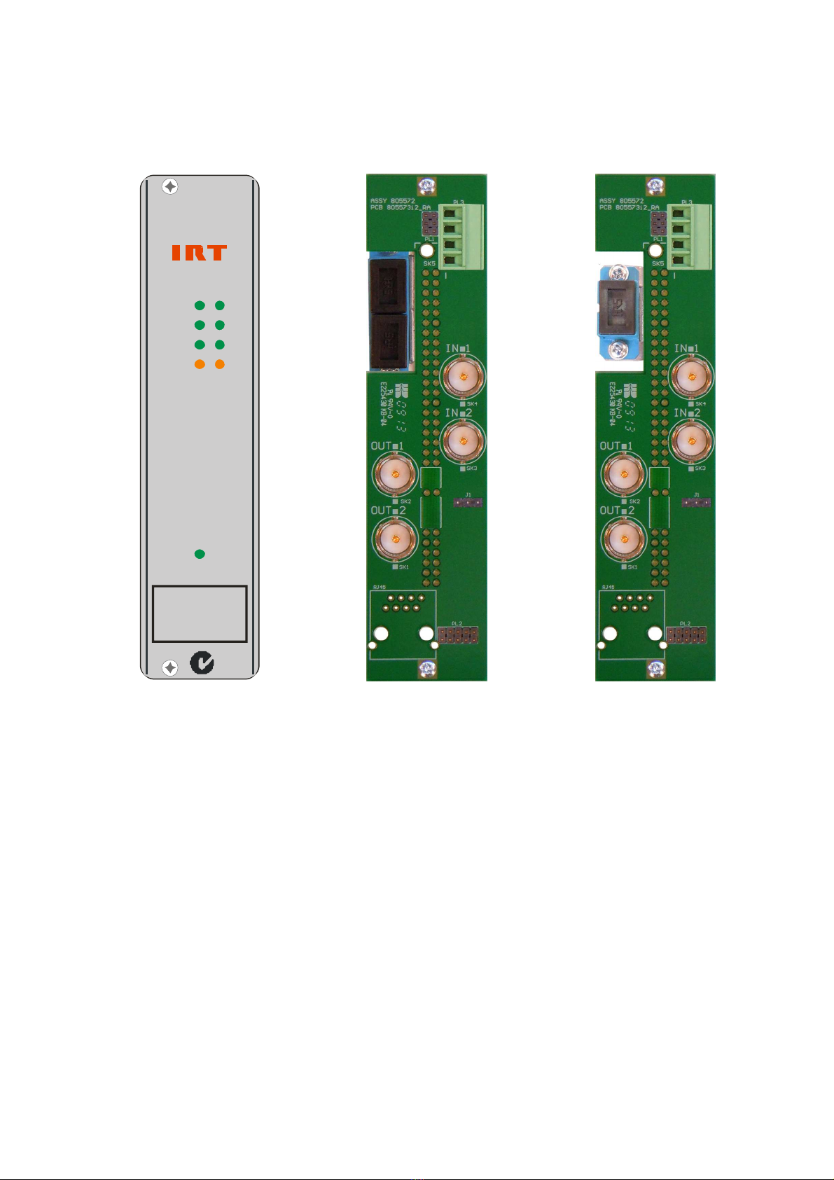
Optical connector 2 x C/PC (standard) on rear – direct connection to main card, 1 Tx and 1 Rx; or
1 x C/PC (standard) with WDM option fitted.
Power Requirements:
oltage 28 Vac CT (14-0-14) or ±16 Vdc.
Power consumption < 5.0 VA.
Other:
Temperature range 0 - 50° C ambient.
Mechanical For mounting in IRT 19" rack chassis with input, output and power connections on the
rear panel.
Finish Front panel Grey, black lettering & red IRT logo.
Rear assembly Detachable silk-screened PCB with direct mount connectors to Eurocard and external
signals.
Dimensions 6 HP x 3 U x 220 mm IRT Eurocard.
Optional accessories On-board 1310/1550nm WDM
6
combiner.
WDM order codes DTR-4630/1310/WDM & DTR-4630/1550/WDM.
NOTE: 4 Typical values based using DFB laser. Optical attenuator supplied for when optical
path loss is less than 3dB for PIN detector and 9dB for APD detector.
5 With WDM option fitted for combined use on a single fibre, optical path loss is
reduced by approximately 2dB.
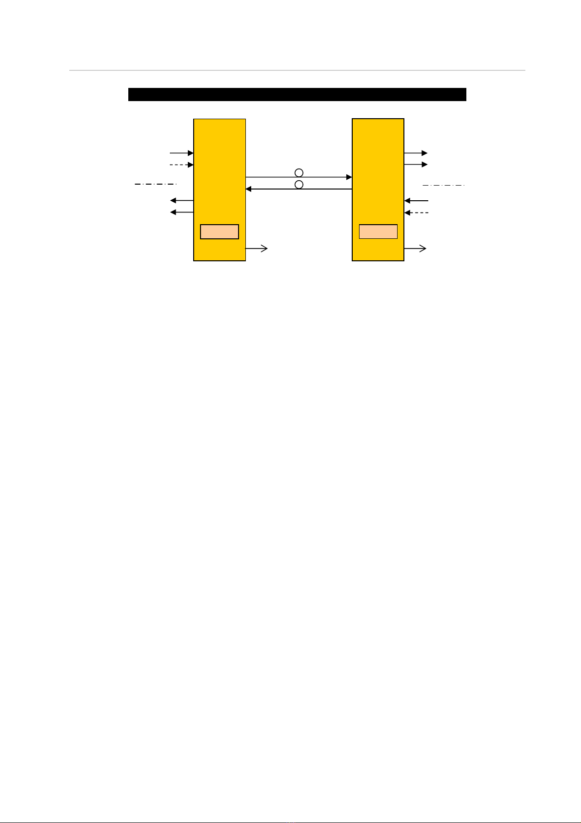
6 With WDM module fitted, when operating as a pair, one DTR-4630 must be fitted
with a 1310nm laser and the other a 1550nm laser.
Due to our policy of continuing development, these specifications are subject to change without notice.

DTR-4630
I.R.
T.
Communications
Pty
L
t
d
|
www
.i
rtcommunication
s.
c
o
m
Page 7 of 17
Revision 02
CONFIGURATION
User DIP switch and link settings:
DIP Switch
Tx Input Rate SW1-1 SW1-2
3G/HD/ D (Auto detect) OFF OFF
D only ON OFF
HD and D only OFF ON
Bypass Reclocker ON ON
DIP Switch
Rx Output Rate SW1-3 SW1-4
3G/HD/ D (Auto detect) OFF OFF
D only ON OFF
HD and D only OFF ON
Bypass Reclocker ON ON
SW1-5 OFF Enable Laser - laser is always enabled: ‘keep link alive’ signal when no input signal is
present.
ON Auto Laser – laser is enabled only when an input signal is present.
SW1-6 OFF Enable automatic input changeover on loss of primary input (IN 1) to Tx.
(IN 1 takes priority over IN 2).
ON Disable automatic input changeover.
SW1-7 OFF DIP switch control.
ON NMP control.
SW1-8 OFF Enable major and minor NMP alarms to the frame Agent (CDM card)
7
.
ON Disable major and minor NMP alarms to the frame Agent (CDM card)
7
.
LK1 OUT OUT 1 acts as the Rx output (both OUT 1 and OUT 2 are Rx outputs).
IN OUT 1 acts as the Tx monitor port (only OUT 2 is the Rx output).
NOTE: 7
When using TRAP via NMP, depending on how system is set up, in order to avoid double
reporting of alarms via the DTR-4630 card and the CDM card ( NMP Agent) of the frame,
major and minor NMP alarms that are reported to the CDM card of the frame can be
disabled.
1
2
3
4
5
6
7
8
ON
DIP
SW1

DTR-4630
I.R.
T.
Communications
Pty
L
t
d
|
www
.i
rtcommunication
s.
c
o
m
Page 8 of 17
Revision 02
INSTALLATION
Pre-installation:
Handling:
This equipment may contain or be connected to static sensitive devices and proper static free handling precautions
should be observed.
Where individual circuit cards are stored, they should be placed in antistatic bags. Proper antistatic procedures
should be followed when inserting or removing cards from these bags.
Power:
AC mains supply: Ensure that operating voltage of unit and local supply voltage match and that correct rating
fuse is installed for local supply.
DC supply: Ensure that the correct polarity is observed and that DC supply voltage is maintained within
the operating range specified.
Earthing:
The earth path is dependent on the type of frame selected. In every case particular care should be taken to ensure
that the frame is connected to earth for safety reasons. ee frame manual for details.
Signal earth: For safety reasons a connection is made between signal earth and chassis earth.
No attempt should be made to break this connection.
Installation in frame or chassis:
ee details in separate manual for selected frame type.
Signal Connections:
The default setting of the DTR-4630 is to automatically operate at either 2.97 Gb/s 3G-SDI, 1.485 Gb/s HD-SDI or
270 Mb/s SD-SDI / ASI signals and do not require any adjustment prior to use, with the exception of link and DIP
switch options described in the Configuration section of this manual that also allow D only, HD/ D only or
reclocker bypass modes of operation.
The transmitter and receiver sections of the DTR-4630 act independently from each other in that the signal rates
are both independently set.
The serial digital signal connections are made to the BNC connectors on the rear panel. IN 1 is the primary input to
the transmitter section of the DTR-4630. With DIP switch W1-6 OFF, IN 2 becomes the secondary input and will
switch in automatically on loss of a valid input to IN1. Upon restoration of a valid signal to the IN 1 port, the optical
transmitter automatically restores back to the signal on the IN 1 port. With W1-6 ON, automatic changeover is
disabled and IN 2 is ignored.
With link LK 1 IN, the OUT 1 BNC connector acts as a monitor port for the transmitter section. It will monitor either
the IN 1 or IN 2 input depending on which input is actually feeding the optical transmitter.
With link LK 1 OUT, the OUT 1 BNC connector acts as one of the optical receiver section outputs. OUT 2 is always
an output of the optical receiver section, regardless of link or DIP switch settings.

DTR-4630
I.R.
T.
Communications
Pty
L
t
d
|
www
.i
rtcommunication
s.
c
o
m
Page 9 of 17
Revision 02
Optical Connections:
Optical connections are made to the panel adapter mounted on a bracket at the rear of the module. Care must be
taken to provide a clean surface on the optical connectors and in inserting the plug on the external fibre to prevent
damage to the alignment ferrule of the panel adapter. Type of fibre used must be single mode type.
The standard configuration for the DTR-4630 has separate optical connectors for the transmitter and receiver
sections. The transmitter optical output connector is the upper half of the optical connector, whilst the receiver
optical input connector is the lower half.
If the DTR-4630 is fitted with the optional 1300/1550nm wave division multiplexer (WDM), only one common
optical connector is provided with both transmit and receive functions occurring on a single fibre. When operating
the DTR-4630 as a pair with the WDM option fitted, one unit must be fitted with a 1310nm (or 1260-1360nm)
optical transceiver and the other with a 1550nm (or 1520-1600nm) optical transceiver.
Note that for path lengths ≤ 9 dB for APD detectors, or ≤ 3 dB for PIN detectors, an optical attenuator must be
used to avoid over driving the receiver part of the transceiver. For the standard DTR-4630 with no WDM option
fitted, an external optical attenuator is supplied as standard with the unit. For DTR-4630’s fitted with a WDM
device, only the 1550nm version comes equipped with an external optical attenuator as it shares the same fibre
together with the 1310nm version.
Alarm Connections:
The external alarm contact connections are made to the 4 pin phoenix style connector at the bottom of the rear
assembly. On an alarm condition relay contacts go open circuit, that is switch open with respect to ground.
The connections being:
The alarms reported are designated as either Major or Minor and relate to either the transmitter or receiver
sections.
A Major alarm is designated as either a laser fail alarm for the transmitter section; or an optical input to the
receiver section is missing, or the optical signal level is absent.
A Minor alarm is designated as either one or both signal inputs are missing or invalid for the transmitter section; or
the optical input level to the receiver is low, or the receiver outputs are muted implying that the electrical signal is
missing or invalid.
Note that when operating the DTR-4630 as either a transmitter or receiver only, Major and Minor alarms may be
reported due to the nature of electrical or optical inputs not being used. It is not possible to disable the other non
used function alarm conditions.
1 GND.
2 GND.
3 Major Alarm.
4 Minor Alarm.

DTR-4630
I.R.
T.
Communications
Pty
L
t
d
|
www
.i
rtcommunication
s.
c
o
m
Page 10 of 17
Revision 02
Front & rear panel connector diagrams
:
N140
CAUTION
Direct
connections
to module
DC
D T R - 4 6 30
OPTICAL
3G
HD
SD
RxTx
eparate
Tx & Rx Fibres
( tandard)
Tx
Rx
Tx Mon.
or Rx O/P
(link select)
Rx O/P
ingle Fibre
WDM version
(option)
Tx Mon.
or Rx O/P
(link select)
Rx O/P
Tx/Rx

DTR-4630
I.R.
T.
Communications
Pty
L
t
d
|
www
.i
rtcommunication
s.
c
o
m
Page 11 of 17
Revision 02
OPERATION
The DTR-4630 is primarily designed for use as an optical transmitter and receiver unit built into the one card, though it
can be operated independently as an optical transmitter or optical receiver only device. The DTR-4630 is fully operable
with previous IRT single channel 3G, HD or D fibre links.
eparate optical transmit and optical receive fibre connectors are provided on the rear of the card with the upper
connector being the optical transmitter output and the lower connector being the optical receiver input.
Optionally a 1300/1550nm wave division multiplexer (WDM) can be fitted to the DTR-4630 to allow simultaneous
transmit and receive functions on the one fibre. Only one optical connector is supplied when fitted with the WDM
option. When fitted with the WDM option, due to the 1300/1550nm split of the WDM device, and being used as a
pair, one DTR-4630 must be fitted with a 1310nm (or 1260-1360nm) transceiver and the other with a 1550nm (or
1520-1600nm) transceiver.
The default setting of the DTR-4630 is automatically set to operate at either 2.97 Gb/s 3G-SDI, 1.485 Gb/s HD-SDI or
270 Mb/s SD-SDI (or ASI) and does not require any adjustments prior to use. However, either DIP switch or NMP
settings allow the unit to be set for D only, D/HD only or reclocker bypass modes.
A 2.97 Gb/s 3G- DI signal, 1.485 Gb/s HD- DI signal or a 270 Mb/s type of signal, such as A I or DI, is connected to
a 75 Ω BNC connector (IN 1) on the rear assembly of the DTR-4630 fibre optic transceiver. Front panel LEDs
indicates the presence and data rate of a valid input signal.
A second input (IN 2) can be automatically switched to the optical output (if enabled) on loss of a valid input signal
to IN 1. On resumption of a valid signal to IN 1 the transmitter section automatically switches back to the IN 1
input.
If the laser is set for permanent operation, on loss of an input signal, a 54MHz oscillator is switched into the optical
output so that the optical receiver still recognizes the optical link as being valid. This 54MHz signal does not affect
the signal reclocking detect circuitry of the receiver section, which is used in signal presence/alarm indication on
detection or absence of a valid 3G, HD or D signal.
ingle mode optical cable is directly connected to the module at the rear of the unit. Likewise the fibre connection
at the far end of the fibre optic cable is directly connected to the rear of the receiver.
The system will operate with an optical path loss from 9dB to a maximum of 27dB (for 3G- DI signals. Typically
>30dB for HD/ D- DI signals) when fitted with an APD detector, and from 3dB to a maximum of 18dB when fitted
with a PIN detector. An orange LED ‘Optical’ indicator on the front panel, and a relay alarm accessible by the rear
assembly, indicates when the optical path loss is approaching, or has exceeded, the maximum allowed. For path
lengths <9dB optical loss when using an APD detector, or <3dB optical loss when using a PIN detector, an optical
attenuator is required. The length of fibre that this corresponds to depends on the fibre loss characteristics at the
relevant wavelength of the laser module chosen. For example, if the fibre loss characteristic of the chosen fibre is
0.2dB per kilometre at 1550 nm, say, then the maximum distance that can be run is 135 km (27dB/0.2dBkm),
although connector losses, such as through patch lead connectors etc., should also be taken into consideration
when calculating maximum distances. Actual attenuation versus wavelength characteristics depends upon optic
fibre manufacturer’s own specifications. Also a few dB headroom is recommended to allow for the effects of laser
aging over time.
The output of the DTR-4630 receiver section is the same signal that was originally inputted to the opposite
DTR-4630 transmitter section. Front panel green LEDs indicate the presence of a valid locked 3G- DI, HD- DI, or an
D- DI type of output signal.
Through the use of NMP (see separate section of manual) it is possible to remotely monitor and control various
functions not available via the local DIP switch control. uch as, for example, it is possible to disable the channel on
either or both the transmitter (Tx) and receiver (Rx) sections locking out an end user’s functionality should this be
desired. When a channel (Tx or Rx) has been disabled, should an electrical signal be present, the corresponding
data rate LED will flash - not to be confused with situation as described in Front Panel LED Indicators section below.

DTR-4630
I.R.
T.
Communications
Pty
L
t
d
|
www
.i
rtcommunication
s.
c
o
m
Page 12 of 17
Revision 02
Front Panel LED Indicators:
If the Tx or Rx input signal rate does not match the set rate, or the secondary input rate is
not the same as the primary input rate, even though its rate is compatible with the set rate,
the corresponding LED will flash.
In this example the transmitter section has been set for either HD/ D only or 3G/HD/ D
operation. The primary input (IN 1) is being fed with an HD source. The secondary input
(IN 2), even though its rate is within the Tx set rate, will flash as its rate is different to the
primary input’s rate. On loss of primary input the secondary will still take control and stop
flashing as its rate is still within the set Tx rate.
If both primary and secondary inputs were HD- DI and 3G- DI signals, for example, and the Tx data rate was set for
D only operation, then both the HD and 3G LEDs will alternatively flash.
Laser failure on the Tx side is indicated by an orange illuminated OPTICAL Tx LED. In the above example there is no
laser failure as indicated by the non-illuminated OPTICAL Tx LED.
Optical Low, or optical input failure, on the Rx side is indicated by an orange illuminated OPTICAL Rx LED. In the
above example the OPTICAL Rx LED is illuminated, but so is the HD Rx signal LED. This indicates that an HD signal is
being received even though the OPTICAL alarm LED is illuminated, thus the OPTICAL alarm LED is likely to be
indicating that the optical signal level is low, or approaching the minimum signal strength allowed before signal
failure takes place, whence the receiver output will be muted. Note however that it is still possible for the optical
signal strength to be low and still allow an errorred data signal to be received before signal muting takes place. This
is because the optical alarm threshold is set for the 3G rate, which has a lower optical path loss than the HD and D
rates. If operating at signal paths close to the recommended maximum specified threshold, signal analysis should
be performed to check the accuracy of the link if the OPTICAL Rx LED is illuminated.
SD only, HD/SD only modes:
Note that it is possible to set the unit to operate as an D rate only or HD/ D rate only mode by use of the DIP
switch configuration controls. However in situations where it is desired that the end user does not have control
over the intended setup, it is possible to set the unit to the desired rate via NMP control and to lock it to NMP
only control so that the end user cannot override the setup parameters by use of the DIP switches. This is intended
for situations where a link has been leased to a customer who is only paying for a certain data rate path such as D
only or HD/ D only as opposed to the full 3G rate.
950 1240 1380
800 1000 1200 1400 1600
Wavelength (nm)
10
1
0.1
Attenuation (dB/km)
IR absorption
Rayleigh scattering
1/λ
4
Figure 1: Attenuation versus wavelength.
Attenuation in the fibre is due to Absorption and cattering.
Tx
Rx
SD
HD
3G
OPTICAL

DTR-4630
I.R.
T.
Communications
Pty
L
t
d
|
www
.i
rtcommunication
s.
c
o
m
Page 13 of 17
Revision 02
SNMP
What Is It?
NMP stands for imple Network Management Protocol. It is an application layer protocol for managing IP
(Internet Protocol) based systems. NMP enables system administrators to manage system performance, and to
find and solve system problems. NMP runs over UDP (User Datagram Protocol), which in turn runs over IP.
Three types of NMP exist: NMP version 1 ( NMPv1), NMP version 2 ( NMPv2) and NMP version 3 ( NMPv3). It
is not the intention here to discuss the differences between various versions, only to bring attention to the fact
that I.R.T. Communications modules, fitted with NMP capability, use NMPv1.
An NMP managed network consists of three key components: Network Management ystems (NMS), agents, and
managed devices.
An NMS is the console through which the network administrator performs network management functions, such
as monitoring status (e.g. alarm states) and remote controlling, of a set of managed devices. One or more NMS’s
must exist on any managed network. Generally the NMS is a computer running third party NMP control software.
There are a number of third party NMP software applications currently available on the market.
An NMS polls, or communicates with, an agent. An agent is a network management software module that resides
in a managed device. An agent has local knowledge of management information and translates that information
into a form compatible with NMP. The agent, therefore, acts as an interface between the NMS and the managed
devices. The NMS sends a request message, and control commands for the managed devices, to the agent, which
in turn sends a response message, containing information about the managed devices, back to the NMS.
A managed device contains an NMP agent and resides on a managed network. Managed devices collect and store
management information and make this information available to NMS’s using NMP.
Managed device agent variables are organised in a tree structure known as a Management Information Base
(MIB). Within the MIB are parameters pertaining to the managed device. An Object Identifier (OID) number within
the MIB defines the managed device type. This is a unique number specific to the model of managed device. Other
information relating to the device is also stored, information such as alarm states, controllable settings, etc. The
MIB tree is organised in such a way that there will be no two MIB files with conflicting placements.
Normally an NMS polls an agent for information relating to the MIB in a managed device to be sent back to the
NMS. When certain conditions are met within the MIB, such as major alarm conditions, for example, the agent
automatically sends what is known as a trap to the NMS without any prompting from the NMS. This allows
automatic notification of a predetermined event.
SNMP Block Diagram
NM
NM
IP
Network
NMP Agent
NMP Agent
Protocol Engine MIB
NMP Agent
NMP Agent
Protocol Engine MIB
NMP Agent
NMP Agent
Protocol Engine MIB

DTR-4630
I.R.
T.
Communications
Pty
L
t
d
|
www
.i
rtcommunication
s.
c
o
m
Page 14 of 17
Revision 02
SNMP with IRT Products:
I.R.T. Communications currently employs NMPv1 with its NMP capable frames. The frame acts as an agent when
fitted with a CDM-xxxx module. This module has its own designated slot next to the power supply so as to not
affect the number of modules that the frame will take. Communication between the NMS, the frame and its
loaded modules are via this CDM-xxxx module. Note that the NMS software is third party and not supplied by I.R.T.
Communications.
Ethernet connection for NMP operation is via an RJ45 connector on the rear of the frame, below the mains inlet.
Ethernet rate runs at either 10 baseT or 100 baseT.
Frame parameters, such as Name, Address and Location, are set via an R 232 interface, a D9 connector on the rear
of the frame below the mains inlet. A software terminal emulator, such as Tera Term or HyperTerminal, is used for
setting and reading the parameters of the frame.
IRT modules that are NMP compatible may need an optional plug-in NMP module with a program relevant to the
module that it is plugged into. Depending on the module, besides the module identification, parameters such as
alarm states, inputs and controls etc. are communicated to the CDM-xxxx agent via a data bus on the rear of the
frame. Thus the CDM-xxxx collects information on what is loaded within the frame, what positions they occupy,
and their current status for communication to the NMS when the NMS sends a request for information.
In the event of a major alarm from any of the NMP compatible modules, or power supplies, a trap is automatically
sent by the CDM-xxxx agent to the NMS without any prompting by the NMS. This alerts the operator to any fault
conditions that may exist that need immediate attention.
FRU-4000
FRAME
110/240 V 50/60 Hz
0.7 A (max.)
FUSES
110/120 Vac
1A S.B.
220/240 Vac
500 mA S.B.
AS3260 approval no.: CS6346N
Ass. no.: 804692
+
-
48Vdc
Alarm
R 232
Ethernet
IRT SNMP Connections
IRT modules fitted
with SMU-4000
PSU’s
CDM
-
xxxx
IRT SNMP Frame
IRT SNMP Frame
IRT modules fitted
with SMU-4000
PSU’s
CDM
-
xxxx
Ethernet Cable
Ethernet Cable
Ethernet Cable
NMS
IRT SNMP Setup
IP
Network

DTR-4630
I.R.
T.
Communications
Pty
L
t
d
|
www
.i
rtcommunication
s.
c
o
m
Page 15 of 17
Revision 02
DTR-4630 SNMP Functions:
When installed in an IRT frame fitted with NMP capability, the DTR-4630 can be interrogated by an NMP Network
Management ystem (NM ). The DTR-4630 belongs to a series of fibre products that share a common framework and
object identifier number (OID), when doing an NMP ‘walk’ via the NM the reported identifier in the slot position list
is reported as being irtDxx463x where the ‘x’ signifies a wildcard character, in this case a ‘T’, ‘R’ and ‘0’ as in the
DTR-4630 product number. The specific product type and details are revealed when expanding this identifier.
The following NMP functions are capable of being monitored by an NM , for NMP control DIP switch W1-7
must be set to ON:
sysDescr
- A description of the unit:
Optical Transceiver
sysObjectID
- irtDTR4630
sysUpTime
- A indication of how long the unit has been running since its last power on or reset in
Days, Hours, Minutes and econds.
sysName
- A 16 character writable system name. Default set name:
DTR-4630
irt463xType
- An indication of the device type:
dtr4630 Transceiver
alarms
- An indication of the alarm type:
(1) noAlarm: No alarms present.
(2) urgent-1: Optical laser of Tx is faulty.
(3) urgent-2: Optical input of Rx is absent.
(4) urgent-1-2: Both urgent alarm conditions are present.
(5) urgent1-nonUrg2: Both urgent-1 and nonUrgent-2 alarm conditions are present.
(6) urgent2-nonUrg1: Both urgent-2 and nonUrgent-1 alarm conditions are present.
(7) nonUrgent-1: Optical Tx output is muted or idling (keep alive signal) indicating
that signal input is missing or invalid.
(8) nonUrgent-2: Optical Rx input is low, or cable output is muted indicating that
signal is either absent or invalid.
(9) nonUrgent-1-2: Both nonUrgent-1 and nonUrgent-2 alarm conditions are present.
ctrlMode
- The current configuration setting’s source as determined by DIP switch W1-7 position:
(1) pcb witches: Configuration set locally via on-board DIP switches ( W1-7 = OFF).
(2) remote NMP: Configuration set remotely via NMP ( W1-7 = ON).
(3) lockToRemote NMP: Lock module to NMP control – overrides W1-7 position.
Note that W1-7 must be initially ON to be able to set to Lock to NMP mode.
To release send either a (1) or (2).
autoChangeOver
- Enable or Disable Automatic Changeover to switch Tx optical output from primary (In 1)
to secondary (IN 2) input on loss of valid primary input (if secondary input is both
present and valid):
(1) disabled: Automatic Changeover mode disabled.
(2) enabled: Automatic Changeover mode enabled.
(3) na: Not applicable. etting this parameter has the same effect as disabled.
channelInfoTable
- Information and control of the transceiver in table form.
channelInfoEntry
- Information and control of the separate transmitter and receiver sections.
channelDesignator
- An indication of the channel designator:
(3) ch-Tx: Primary signal input (IN 1) and Optical Transmitter settings column designator.
(4) ch-Rx: Optical Receiver settings column designator.
(6) ch-Tx2: econdary signal input (IN 2) information column designator.
inputStatus
- An indication of the signal rate present:
(1) unknownPresent: ignal rate is not one of the 3G/HD/ D- DI/A I rates.
(2) sdi D-A I-Present: ignal is either an D- DI or A I signal, or at 270 Mb/s rate.
(3) sdiHD-Present: ignal is either an HD- DI signal, or at 1.485 Gb/s rate.
(4) sdi3G-Present: ignal is either an 3G- DI signal, or at 2.97 Gb/s rate.
(5) notPresent: No signal is present.

DTR-4630
I.R.
T.
Communications
Pty
L
t
d
|
www
.i
rtcommunication
s.
c
o
m
Page 16 of 17
Revision 02
dataRateSet
- Control of the signal data rate setting:
(1) sdi3G-HD- D-A I: Reclocker set to 3G- DI, HD- DI or D- DI/A I rates.
(2) sdiHD- D-A I-only: Reclocker set to HD- DI (1.485 Gb/s) and D- DI/A I
(270 Mb/s) rates only.
(3) sdi D-A I-only: Reclocker set to D- DI/A I (270 Mb/s) rate only.
(4) bypassed: Reclocker bypassed to allow other signal rates through.
(5) na: Not Applicable. If selected defaults to 3G/HD/ D- DI/A I rate setting.
channelEnable
- An indication of how and whether the channel is enabled:
(1) notEnabled: Disable of the electrical signal on either the Tx or Rx.
(2) enabledActive: Electrical signal is both Enabled and Active. For Tx, relates to IN 1.
(3) enabledMuted: Electrical signal is Enabled, but the output is Muted when no
signal is present.
(4) enabledChangedOver: Relates to Tx only. Reported if autoChangeOver is enabled
and signal on IN 1 is missing with a valid signal on IN 2 indicating that IN 2 is
being transmitted.
(5) na: Not Applicable.
channelAlias
- A 16 character maximum Alias (name) for the signal can be read and set.
blankLine
- A line spacing within the table to make reading the table easier.
channelKeepAlive
- Relates to Tx only. A substitution of a 54 MHz signal in place of no input signal to keep
the optical link active at the receiver end:
(1) on: Keep Alive signal active.
(2) off: Keep Alive signal not active.
(3) na: Not Applicable.
chanPresTrapEnable
- Enable or Disable Traps
8
to be sent when the electrical signal condition changes:
(1) notEnabled: No Traps sent on change of electrical signal presence.
(2) enabled: Traps automatically sent on change of electrical signal presence.
(3) na: Not Applicable.
opticalStatus
- An indication of how the FP optical component is functioning:
(1) opticalGood: Tx laser is present; Rx optical input level is good.
(2) opticalLow: Rx optical input level is approaching or has exceeded its limit.
Electrical signal presence at receiver also reported (may or may not contain
signal errors).
(3) opticalFail: Tx laser has failed or is not present; Rx optical input level is
approaching or has exceeded its limit. No electrical signal present or signal is not
at one of the settable 3G/HD/ D- DI rates.
(4) na: Not Applicable.
waveLength
- An indication Tx laser wavelength. Not applicable to Rx section.
detectorType
- An indication Rx detector type – APD or PIN. Not applicable to Tx section.
opticalTrapEnable
- Enable or Disable Traps
9
to be sent when the optical signal condition changes:
(1) notEnabled: No Traps sent on change of optical signal presence.
(2) enabled: Traps automatically sent on change of optical signal presence.
(3) na: Not Applicable.
fpga ersion
- An indication of the firmware version of the microcontroller in the format ‘x.y’, where
x is the major revision number and y the minor.
reset
- Unit reset control:
(1) normal: when queried reset control returns a ‘normal’ state.
(2) reset: system reset causes ‘sysUpTime’ counter to reset.
NOTE: 8
TRAP names - irt4630DTRChan1Trap (Input tatus(1)) relates to Tx IN 1 input;
irt4630DTRChan2Trap (Input tatus(2)) relates to Rx output; and
irt4630DTRChan3Trap (Input tatus(3)) relates to Tx IN 2 input.
9
TRAP names - irt4630DTROptiCh1Trap (opti tatus(1)) relates to Tx optical output; and
irt4630DTROptiCh2Trap (opti tatus(2)) relates to Rx optical input.

DTR-4630
I.R.
T.
Communications
Pty
L
t
d
|
www
.i
rtcommunication
s.
c
o
m
Page 17 of 17
Revision 02
MAINTENANCE & STORAGE
Maintenance:
No regular maintenance is required.
Care however should be taken to ensure that all connectors are kept clean and free from contamination of any
kind. This is especially important in fibre optic equipment where cleanliness of optical connections is critical to
performance.
Storage:
If the equipment is not to be used for an extended period, it is recommended the whole unit be placed in a sealed
plastic bag to prevent dust contamination. In areas of high humidity a suitably sized bag of silica gel should be
included to deter corrosion.
Where individual circuit cards are stored, they should be placed in antistatic bags. Proper antistatic procedures
should be followed when inserting or removing cards from these bags.
WARRANTY & SER ICE
Equipment is covered by a limited warranty period of three years from date of first delivery unless contrary
conditions apply under a particular contract of supply. For situations when “No Fault Found” for repairs, a
minimum charge of 1 hour’s labour, at IRT’s current labour charge rate, will apply, whether the equipment is
within the warranty period or not.
Equipment warranty is limited to faults attributable to defects in original design or manufacture. Warranty on
components shall be extended by IRT only to the extent obtainable from the component supplier.
Equipment return:
Before arranging service, ensure that the fault is in the unit to be serviced and not in associated equipment. If
possible, confirm this by substitution.
Before returning equipment contact should be made with IRT or your local agent to determine whether the
equipment can be serviced in the field or should be returned for repair.
The equipment should be properly packed for return observing antistatic procedures.
The following information should accompany the unit to be returned:
1. A fault report should be included indicating the nature of the fault
2. The operating conditions under which the fault initially occurred.
3. Any additional information, which may be of assistance in fault location and remedy.
4. A contact name and telephone and fax numbers.
5. Details of payment method for items not covered by warranty.
6. Full return address.
7. For situations when “No Fault Found” for repairs, a minimum charge of 1 hour’s labour will apply,
whether the equipment is within the warranty period or not. Contact IRT for current hourly rate.
Please note that all freight charges are the responsibility of the customer.
The equipment should be returned to the agent who originally supplied the equipment or, where this is not
possible, to IRT directly. Details of IRT’s direct address can be found at I.R.T. Communications’ website.
Web address: www.irtcommunications.com
Email: [email protected]
Table of contents
Other IRT Transceiver manuals
Popular Transceiver manuals by other brands

American Communication Systems
American Communication Systems VX-510 operating manual

Sporty's
Sporty's SP-400 operating manual

Midland
Midland G10 Instruction guide

Hilberling
Hilberling PT-8000A operating manual

MGL Avionics
MGL Avionics V6 User & installation manual

Standard Horizon
Standard Horizon Hx750s owner's manual