Page 1FT-991
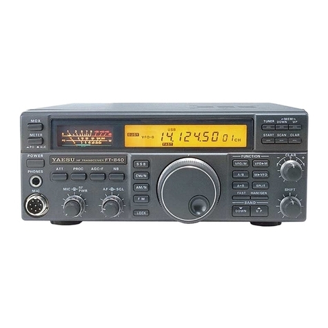
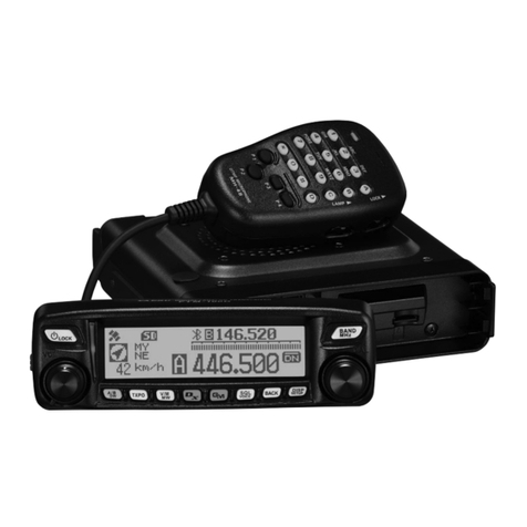
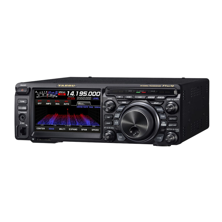
The is equipped with a 3.5 inch full-color TFT
display. Functions, including the receiving band, the noise
and signal interference reduction tools are graphically
displayed. Even while performing rigorous operations,
during DX pditions or contests, the operator may instantly
grasp the status of each function.
This transceiver C4FM mode provides good error cor-
rection performance, and supports the V/D mode (voice/
data simultaneous transmission mode)which makes the
transceiver suitable for mobile communication, and the
Voice FR mode (voice full rate mode)which allows the
transceiver to transmit high quality digital audio. The AMS
function recognizes the contacting stations transmission
method and automatically switches the transceiver to the
same C4FM digital or analog (FM)communications mode
as the received signal.
The two-digit DG-ID numbers (00 to 99) can be set
separately for Transmit and Receive. By setting both
transmit and receive to “00”, communication with all
the other stations in the digital C4FM mode is possible,
regardless of their DG-ID number setting. Matching the
transmit DG-ID number to the uplink DG-ID number set
in the DR-2X System Fusion II digital repeater, will permit
access to the digital repeater DR-2X used by the club.
Every C4FM digital transmit communication contains
the individual ID information (Radio ID) of each
transceiver. The DP-ID function uses this individual ID
information. When the DP-IDs of the transceiver are
registered with each other, they can communicate even
if the DG-ID numbers are dierent. By registering the
DP-ID of the transceiver to the DR-2X System Fusion II
digital repeater, the digital repeater may be controlled by
remote operation.
The transceiver automatically checks the channel fre-
quency for registered member stations that are within com-
municating range. The distance and direction information
of the call sign members of the group may be shown on
the TFT display.
This transceiver is equipped with two types of roong l-
ters for 3 kHz and 15 kHz bandwidths. These narrow band
lters are especially useful on a very crowded band during
contests, because they can dramatically attenuate powerful
out-of-band signals in the rst IF stage and reduce their
impact in the second stage to further optimizing the excel-
lent dynamic range and IP3 characteristics for processing
signals ranging from faint to powerful.
Congure the front end RF circuitry for the precise gain and
performance to suit the conditions of each HF band.Select
the IPO (Intercept Point Optimization)feature to optimize
the proximal multi-signal and mutual modulation character-
istics in order to minimize the eects of powerful broadcast
stations, especially in the low-band so that even the faintest
signals can be received. When higher gain is advantageous,
select the single low noise RF amplier AMP1. In the high
bands, adding AMP2 provides maximum useful gain.
The 30.225 MHz standard oscillator provides exceptional
frequency stability. It is temperature compensated and boasts
an enhanced ±0.5 ppm stability from −10°C to +50°C.
The SHIFT feature, can eliminate interference in one side
of the passband. The WIDTH feature allows the bandwidth
to be narrowed by rotating the WIDTH knob. The moment
weak signals disappear due to interfering signals (includ-
ing pile-ups), you can eliminate the interfering signals and
extract only the desired signal, thanks to the unique DSP
sharp ltering characteristic.
Rather than using the DSP extremely sharp attenuation
characteristics, the CONTOUR circuit provides gentle
shaping of the DSP passband lter and can thus attenuate
or peak bandwidth components in segments. The interfer-
ing signal can be naturally shaped without having part of
the signal suddenly interrupted. The contour function is
very eective in making the desired signal rise out of the
interference.
