Yaesu FT-817ND User manual

HF/VHF/UHF
ALL MODE TRANSCEIVER
FT-817
ND
OPERATING MANUAL
VERTEX STANDARD CO., LTD.
4-8-8 Nakameguro, Meguro-Ku, Tokyo 153-8644, Japan
VERTEX STANDARD
US Headquarters
10900 Walker Street, Cypress, CA 90630, U.S.A.
YAESU UK LTD.
Unit 12, Sun Valley Business Park, Winnall Close
Winchester, Hampshire, SO23 0LB, U.K.
VERTEX STANDARD HK LTD.
Unit 1306-1308, 13F., Millennium City 2, 378 Kwun Tong Road,
Kwun Tong, Kowloon, Hong Kong
VERTEX STANDARD (AUSTRALIA)PTY., LTD.
Tally Ho Business Park, 10 Wesley Court, East Burwood, VIC, 3151

Introduction .................................................... 1
Specifications .................................................. 2
Accessories & Options .................................... 4
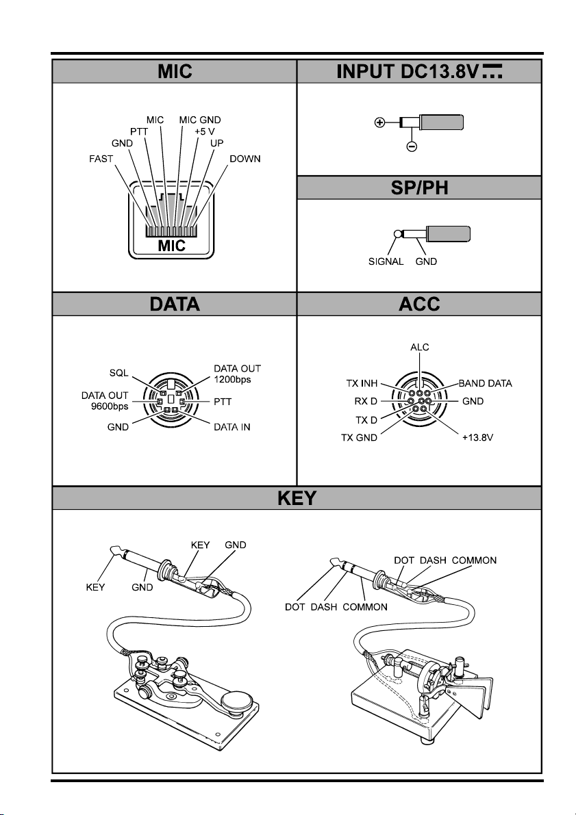
Plug Pinout ...................................................... 5
Installation ...................................................... 6
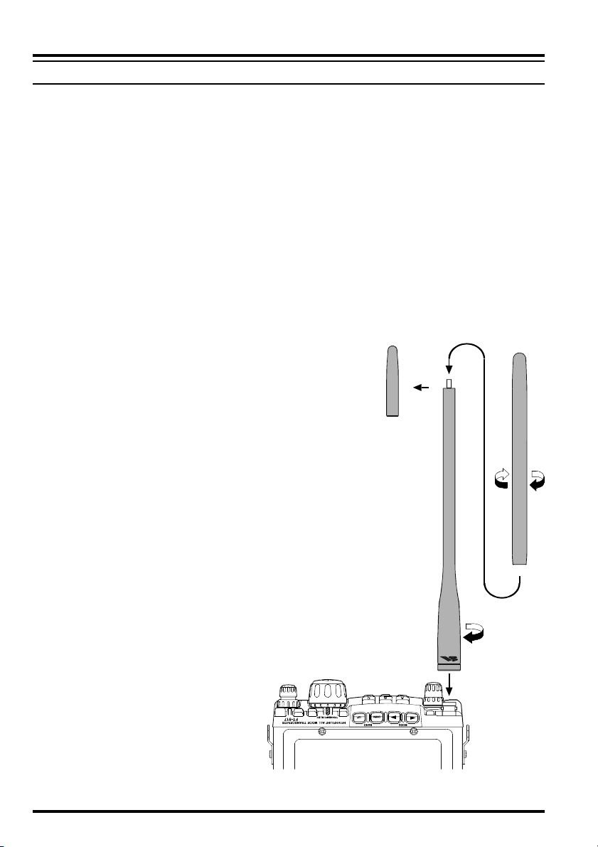
Connecting the Supplied YHA-63 Antenna ......... 6
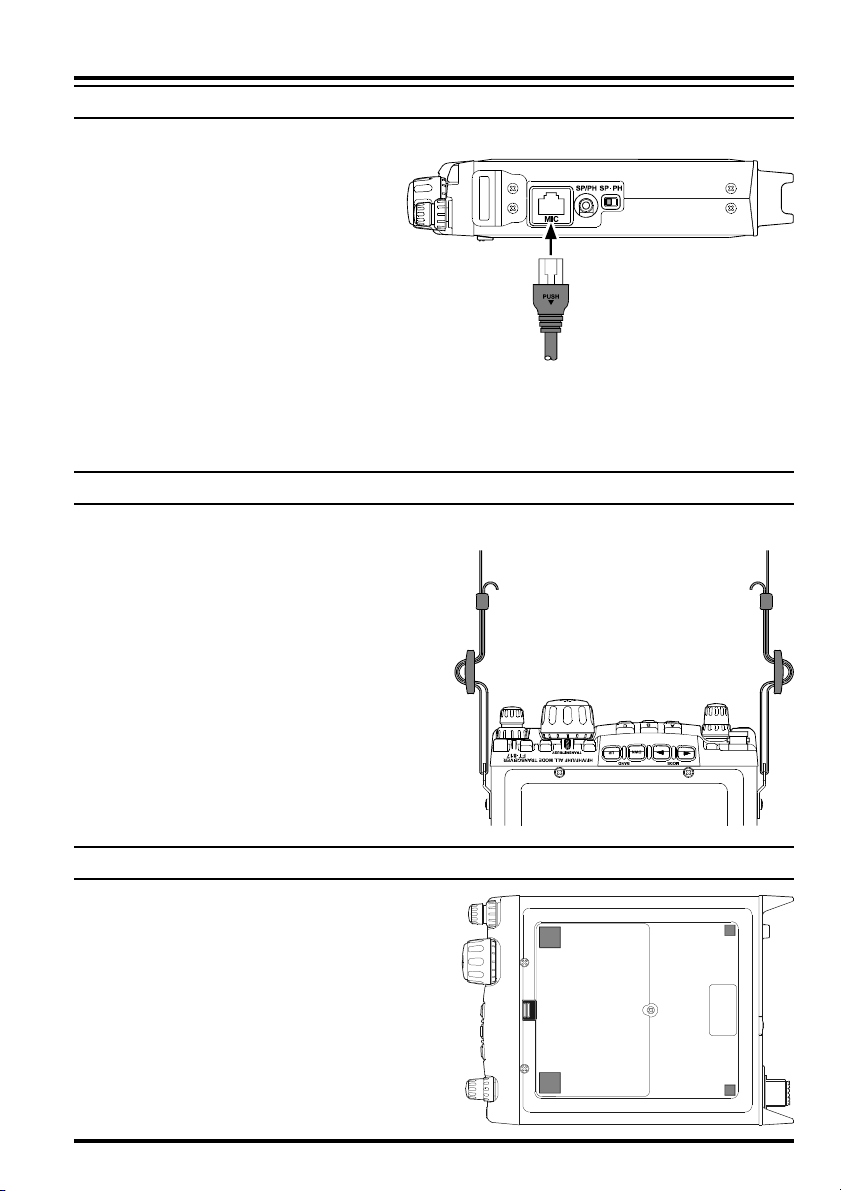
Connecting the Microphone ................................. 7
Shoulder Strap Installation ................................... 7
Rubber Foot Installation ....................................... 7
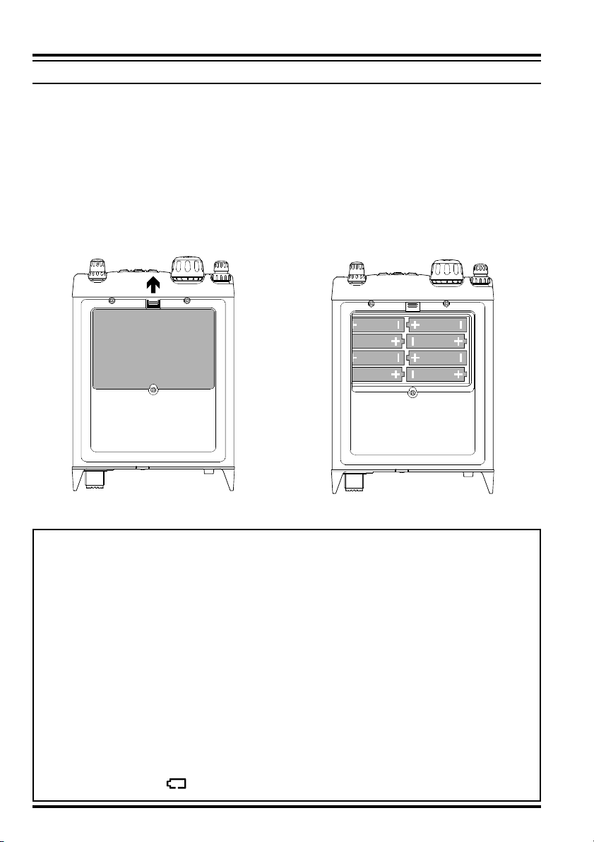
Alkaline Battery Installation and Use ................... 8
External Power Connections ................................ 9
FNB-85 Ni-Cd Battery Pack Installation and Use
... 10
Front Panel Control & Switches ................. 12
Side Panel Switch & Connectors ................. 16
Rear Panel Connectors ................................. 17
Operation ...................................................... 18
Turning the Transceiver On and Off ................... 18
Supply Voltage Display ...................................... 18
Operating Band Selection ................................... 19
Mode Selection ................................................... 19
Adjusting the Audio Volume Level .................... 19
Menu Quick Start ................................................ 20
Adjusting the RF Gain and Squelch ................... 20
Setting the Operating Frequency ........................ 21
Stacked VFO System .......................................... 21
Operation on 5 MHz Band
(U.S. Version Only) ............................................ 22
Receiver Accessories ..................................... 23
Clarifier (Receiver incremental Tuning) ............. 23
IF SHIFT ............................................................. 24
AGC (Automatic Gain Control) ......................... 25
Noise Blanker ..................................................... 25
IPO (Intercept Point Optimization) .................... 25
ATT (Front End Attenuator) ............................... 26
AM/FM DIAL .................................................... 26
Automatic Power-Off Feature ............................ 27
Transmitter Operation ................................. 28
SSB Transmission ............................................... 28
Basic Setup/Operation ................................... 28
Adjusting the transmitter Power Output ... 28
VOX Operation .............................................. 29
CW Transmission ............................................... 30
Operation using Straight Key/
External Keying Device ................................. 30
Operation using
the Built-in Electronic Keyer ......................... 32
FM Transmission ................................................ 33
Basic Setup/Operation ................................... 33
Repeater Operation ........................................ 33
Tone Search Scanning ............................... 35
DCS Operation ............................................... 36
DCS Search Scanning ............................... 36
ARTS
TM
(Auto Range Transpond System)
Operation ....................................................... 37
CW Identifier Setup ....................................... 37
Digital Mode Operation (SSB-Based AFSK) ..... 38
RTTY (Radio TeleType) Operation ................ 38
PSK31 Operation ........................................... 39
“USER” Defined Digital Modes .................... 40
Packet (1200/9600 bps FM) Operation .............. 41
AM Transmission ............................................... 42
Split Frequency Operation .................................. 42
Time-Out Timer .................................................. 43
WeatherFax Monitoring ...................................... 43
Memory Operation ....................................... 44
QMB Channel ..................................................... 44
Memory Operation on
“Regular” Memory Channels ............................. 45
Normal Memory Storage .............................. 45
Split-Frequency Memory Storage .................. 45
Memory Channel Recall ................................ 46
Masking Memory ........................................... 47
Memory Operation on
“HOME” Channel Memories ............................. 48
Labeling Memories ............................................. 49
Spectrum Scope Monitor Operation ........... 50
Smart SearchTM Operation .......................... 51
Scanning Operation ...................................... 52
Scanning Operation ............................................ 52
Scan Skip Programming (
Memory Mode Only
) ..... 52
Scan-Resume Choices ............................... 52
Programmable Memory Scan (PMS) Operation .. 54
Dual Watch Operation ................................. 56
Operation on Alaska Emergency Frequency:
5167.5 kHz (U.S. Version Only)
......................... 57
Menu Operation ........................................... 58
Clonning ........................................................ 69
CAT System Programming ........................ 70
Installation of Optional Accessories ............ 74
Option Filters
YF-122S/YF-122C/YF-122CN
..... 74
High-Stability Reference Oscillator TCXO-9 .... 75
Power-on Microprocessor Reset Procedure
....... 76
Appendix ....................................................... 77
Setup of Memories for Low Earth Orbit (LEO)
FM Satellite Operation ....................................... 77
BAND DATA Format ......................................... 80
Contents

1FT-817ND Operating Manual
The FT-817ND is a compact, innovative multiband, multimode portable transceiver for the
amateur radio MF/HF/VHF/UHF bands. Providing coverage of the 160-10 meter bands
(include the 60 m band: USA version) plus the 6 m, 2 m, and 70 cm bands, the FT-817ND
includes operation on the SSB, CW, AM, FM, and Digital modes, yielding the most com-
prehensive performance package available for portable operation.
Designed for use either from an external DC power source or internal batteries, the FT-
817ND provides five watts of power output from a 13.8-Volt external power supply. When
using the FNB-85 Ni-MH Battery Pack or 8 “AA” Alkaline Cells (not supplied), the FT-
817ND automatically switches to 2.5 Watts of output power. Via the Menu system, “High”
power may be selected during battery operation, providing as much as 5 Watts of output,
depending on the operating frequency.
The multi-function Liquid-Crystal Display includes Blue, Amber, and Violet backlighting,
which may be disabled for battery conservation. The display includes bar-graph indication
of power output, ALC voltage, SWR, and modulation level. Also include are a number of
operating status icons, as well as the function displays for the three operating function keys
(, , and ).
Among the advanced features of the FT-817ND are many incorporated only in large base-
station transceivers. These include Dual VFOs; Split-Frequency operation; IF Shift; Clari-
fier (“R.I.T.”); IF Noise Blanker; AGC Fast/Slow/Auto/Off selection; RF Gain and Squelch
control; IPO (Intercept Point Optimization) and a receiver front-end Attenuator; AM Air-
craft reception; AM and FM Broadcast reception; VOX; Built-in Electronic Keyer; Adjust-
able CW Pitch; Automatic FM Repeater Shift (ARS); Built-in CTCSS Encoder/Decoders;
ARTS™ (Auto-Range Transponder System); Smart Search™ Automatic Memory Loading
System; Spectrum Scope; 200 Memories plus Home Channels and Band-limiting Memo-
ries; Alpha-Numeric Labeling of Memories; Automatic Power-Off (APO) and Time-Out
Timer (TOT) functions; Computer Interface capability; and Cloning capability.
We urge you to read this manual in its entirety, so as to gain a full understanding of the
amazing capability of the exciting FT-817ND Portable Transceiver.
INTRODUCTION

2 FT-817ND Operating Manual
GENERAL
Frequency Range: Receive: 100 kHz-30 MHz
50 MHz-54 MHz
76 MHz-154 MHz
420 MHz-470 MHz
Transmit: 160-6 Meters (USA: includes 60 meters)
2 Meters
70 Centimeters (Amateur bands only)
5.1675 MHz Alaska Emergency Frequency (USA only)
Emission Modes: A1A (CW), A3E (AM), J3E (LSB/USB), F3E (FM),
F1D (9600 bps packet), F2D (1200 bps packet)
Synthesizer Steps (Min.): 10 Hz (CW/SSB), 100 Hz (AM/FM)
Antenna Impedance: 50 Ohms, Unbalanced (Front: Type BNC, Rear: Type M)
Operating Temp. Range: –10 °C to +60 °C (+14 °F to +140 °F)
Frequency Stability: ±4 ppm from 1 min. to 60 min after power on.
@25 °C: 1 ppm/hour
±0.5 ppm/1 hour @25 °C, after warmup (with optional TCXO-9)
Supply Voltage: Normal: 13.8 VDC ± 15 %, Negative Ground
Operating: 8.0-16.0 V, Negative Ground
FBA-28 (w/8 “AA” Alkaline Cells): 12.0 V
FNB-85 (Ni-MH Battery Pack): 9.6 V
Current Consumption: Squelched: 250 mA (Approx.)
Receive: 450 mA
Transmit: 2.2 A (HF/145 MHz), 2.5 A (430 MHz)
Case Size (W x H x D): 135 x 38 x 165 mm (5.31” x 1.5” x 6.50”)
Weight (Approx.): 1.17 kg (2.58 lb) w/Alkaline battery, antenna, w/o Microphone
TRANSMITTER
RF Power Output: 5 W (SSB/CW/FM), 1.5 W (AM Carrier) @13.8 V
Modulation Types: SSB: Balanced Modulator
AM: Early Stage (Low Level)
FM: Variable Reactance
FM Maximum Deviation: ±5 kHz (FM-N: ±2.5 kHz)
Spurious Radiation: –50 dB (1.8-29.7 MHz)
–60 dB (50/144/430 MHz)
Carrier Suppression: >40 dB
Opp. Sideband Supp.: >50 dB
SSB Frequency Response: 400 Hz-2600 Hz (–6 dB)
Microphone Impedance: 200-10k Ohms (Nominal: 600 Ohms)
SPECIFICATIONS

3FT-817ND Operating Manual
RECEIVER
Circuit Type: Double-Conversion Superheterodyne
Intermediate Frequencies:1st: 68.33 MHz (SSB/CW/AM/FM); 10.7 MHz (WFM)
2nd: 455 kHz
Sensitivity:SSB/CW AM FM
100 kHz-500 kHz – – –
500 kHz-1.8 MHz – 32 µV –
1.8 MHz-28 MHz 0.25 µV 2 µV –
28 MHz-30 MHz 0.25 µV 2 µV 0.5 µV
50 MHz-54 MHz 0.2 µV 2 µV 0.32 µV
144/430 MHz 0.125 µV – 0.2 µV
(IPO, ATT off, SSB/CW/AM = 10 dB S/N, FM = 12 dB SINAD)
Squelch Sensitivity: SSB/CW/AM FM
1.8 MHz-28 MHz 2.5 µV –
28 MHz-30 MHz 2.5 µV 0.32 µV
50 MHz-54 MHz 1 µV 0.2 µV
144/430 MHz 0.5 µV 0.16 µV
(IPO, ATT off)
Image Rejection: HF/50 MHz: 70 dB
144/430 MHz: 60 dB
IF Rejection: 60 dB
Selectivity (–6/–60 dB): SSB/CW: 2.2 kHz/4.5 kHz
AM: 6 kHz/20 kHz
FM: 15 kHz/30 kHz
FM-N: 9 kHz/25 kHz
SSB (optional YF-122S installed): 2.3 kHz/4.7 kHz (–66 dB)
CW (optional YF-122C installed): 500 Hz/2.0 kHz
CW (optional YF-122CN installed): 300 Hz/1.0 kHz
AF Output: 1.0 W (8 Ohms, 10% THD or less)
AF Output Impedance: 4-16 Ohms
Specifications are subject to change without notice, and are guaranteed within amateur
bands only.
Frequency ranges vary according to transceiver version; check with your dealer.
SPECIFICATIONS

4 FT-817ND Operating Manual
SUPPLIED ACCESSORIES
MH-31A8J Hand Microphone
FNB-85 Ni-MH Battery Pack (9.6 V, 1400 mAh)
NC-72B/C/Uor PA-48C/UBattery Charger
FBA-28 Battery Case
(holds 8 “AA” size Alkaline cells [not supplied])
YHA-63 Whip Antenna for (50/144/430 MHz)
E-DC-6 DC Cable
Shoulder Strap
Ferrite Core
Rubber Foot
Available Options
FNB-85 Ni-MH Battery Pack (9.6 V, 1400 mAh)
FNB-72 Ni-Cd Battery Pack (9.6 V, 1000 mAh)
NC-72B/C/Uor PA-48C/UBattery Charger
YF-122S Collins SSB Filter (2.3 kHz/4.7 kHz: –6 dB/–66 dB)
YF-122C Collins CW Filter (500 Hz/2 kHz: –6 dB/–60 dB)
YF-122CN Collins CW Filter (300 Hz/1 kHz: –6 dB/–60 dB)
TCXO-9 TCXO Unit (±0.5 ppm)
MH-36E8J DTMF Microphone
CT-62 CAT Interface Cable
CT-39A Packet Cable
:“B” suffix is for use with 120 VAC, “C” suffix is for use with 230-240 VAC, and “U”
suffix is for use with 230 VAC.
ACCESSORIES & OPTIONS

5FT-817ND Operating Manual
PLUG PINOUT

6 FT-817ND Operating Manual
CONNECTING THE SUPPLIED YHA-63 ANTENNA
Your FT-817ND is supplied with a three-section antenna, model YHA-63 which is designed
for optimum performance on the 50 MHz, 144 MHz, and 430 MHz. It also works well on
the FM broadcast and other VHF bands. This antenna is intended for connection to the front
panel’s BNC-type antenna connector.
For HF and/or 50 MHz operation, most hikers carry their own dipole or collapsible vertical
antenna, fed by a small-diameter coaxial cable terminated in a type “M” (PL-259) plug, and
these kinds of antennas may be connected to the rear panel’s antenna connector.
The YHA-63 should be connected to the top panel’s “BNC” connector, using the following
guidelines:
For 144/430 MHz operation (only), connect the shorter cap section to the screw post on
the top of the main antenna shaft, then screw the assembled YHA-63 onto the BNC
connector, twisting it 1/4 turn clockwise to secure the antenna.
For 50 MHz operation, unscrew the
short cap section, and replace it with
the long cap section. The long cap
section will provide good results on
144/430 MHz, as well, but those
owners not using 50 MHz may pre-
fer the shorter total length of the
YHA-63 when using the short cap
on 144/430 MHz.
For shortwave listening using a ran-
dom-length wire antenna for recep-
tion only, you may wish to consider
connection of the wire between the
main YHA-63 shaft and the cap,
using a “spade lug” or similar lug
on the end of the wire to provide a
secure connection between the cap
and the rest of the antenna.
Menu #07 (“ANTENNA”) allows
you to define which connector
(“Front” or “Rear”) is used on a
particular band. See page 60 for de-
tails.
INSTALLATION

7FT-817ND Operating Manual
INSTALLATION
CONNECTING THE MICROPHONE
To connect the microphone, plug its connector (latch side UP) into the MIC jack on the
right side of the transceiver. Press it
gently inward until you hear the
“click” of the latch.
To disconnect the microphone, press
gently on the “PUSH ” label on
top of the microphone connector’s rubber boot.
While pressing on this spot, gently pull the con-
nector outward from the body of the transceiver.
Note: During “Digital” or “Packet” operation, it is not necessary to disconnect the micro-
phone, as activation of the PTT line from the DATA connector automatically cuts off the
audio input from the MIC jack.
SHOULDER STRAP INSTALLATION
The convenient Shoulder Strap is designed for maximum comfort and security for your FT-
817ND transceiver.
Refer to the illustration, and connect the
shoulder strap to the attachment tabs just
behind the front panel of the FT-817ND.
Be sure to have the shoulder strap aligned
correctly, without twists in the straps.
A convenient microphone hanger is lo-
cated on one end of the padded top sec-
tion of the Shoulder Strap. When not in
use, the microphone may be affixed here,
freeing both of your hands for other tasks.
RUBBER FOOT INSTALLATION
Four Rubber Feet are provided with your FT-
817ND, for ease of use when operating from a
base station or camp table.
Refer to the illustration, and affix the Rubber
Feet in the appropriate locations.

8 FT-817ND Operating Manual
ALKALINE BATTERY INSTALLATION AND USE
The FT-817ND is supplied with the FBA-28 holder for Alkaline “AA” cells. A fresh set of
Alkaline cells should provide approximately 5.5 hours of reception under typical conditions.
1. To install or replace the AA cells, first remove the battery cover from the bottom side of
the transceiver. Slide the battery cover latch forward, as shown in the illustration, then
fold the battery cover upward and set it aside temporarily.
2. Install the Alkaline AA cells as shown in the illustration, paying particular attention to
the correct polarity of the batteries.
3. When all batteries have been successfully installed, replace the battery cover.
INSTALLATION
Important Notes
When the transceiver is to be stored for a long period of time without use (longer
than ten days), remove the batteries from the FBA-28 holder, to avoid the possi-
bility of battery leaking causing damage to the transceiver. Inspect the FBA-28
battery holder occasionally for signs of corrosion or battery leakage, and remove
the batteries immediately if any such damage is observed.
The FBA-28 battery holder is designed for use solely with Alkaline type “AA”
cells. Do not attempt to use Ni-Cd or other rechargeable cells in the FBA-28,
because it does not contain the protection circuitry required when using recharge-
able cells.
When replacing batteries, replace all eight AA cells simultaneously with fresh
batteries.
When the battery voltage is approaching the value which indicates depletion is
near, the small “ ” will blink, indicating it is time to replace the batteries.

9FT-817ND Operating Manual
INSTALLATION
EXTERNAL POWER CONNECTIONS
The FT-817ND may be connected to an external 13.8 Volt DC power source providing at
least 3 Amps of continuous-duty current.. The supplied E-DC-6 DC cable may be used for
DC connections.
While connected to an external DC source, if you have installed the supplied FNB-85 Ni-
MH Battery Pack, the E-DC-6 connection to the external DC power source will allow
operation of the FT-817ND while charging of the FNB-85 is in progress.
When making DC power connections, be absolutely certain to follow the markings on the
E-DC-6 so as to ensure proper polarity of the connection to the power supply. Connect the
RED AND BLACK wire to the Positive (+) power supply terminal, and connect the SOLID BLACK
wire to the Negative (-) power supply terminal.
Notice
Be extremely careful when making power supply connections. Use only a 13.8 Volt
DC Supply, and carefully observe the proper electrical polarity. Serious damage
may result if these precautions are not observed.
The Limited Warranty on this product does not cover damage caused by improper
power supply connections, or improper power supply voltage.
FT-817ND

10 FT-817ND Operating Manual
FNB-85 NI-MH BATTERY PACK INSTALLATION AND USE
The supplied FNB-85 Ni-MH Battery Pack provides 9.6 Volts of DC power for your FT-
817ND, with a maximum capacity of 1400 mAh.
Installation
1. To install the FNB-85 Ni-MH Battery Pack, first remove the battery compartment cover,
as described previously.
2. Lift out the FBA-28 battery holder, and disconnect the short cable connected to the
FBA-28, as shown in the illustration.
3. Connect the short cable to the mating connector on the FNB-85, and install the FNB-
85 in the battery compartment.
4. Replace the battery compartment cover.
INSTALLATION
FNB-85
FBA-28

11FT-817ND Operating Manual
FNB-85 NI-MH BATTERY PACK INSTALLATION AND USE
INSTALLATION
Charging
Charging of the FNB-85 requires the use of either the supplied battery charger (NC-72B/
Cor PA-48C/U), or an external 13.8 Volt (±15%) DC source. If the battery charger is used,
the FT-817ND must be turned off during charging; if an external 13.8 Volt DC source is
used (connected via the supplied E-DC-6 cable), then you may operate the FT-817ND while
charging is in progress.
1. Turn the FT-817ND off (see page 18), then connect the supplied battery charger DC
connector to the INPUT: 13.8V jack on the rear panel of the FT-817ND.
2. Plug the battery charger into the nearest AC wall outlet.
3. Press the FT-817ND’s switch for one second to turn the transceiver on.
4. Press the key momentarily.
5. Rotate the knob so that the function row containing “[CHG, VLT, DSP]” appears
on the display.
6. Press the key to select the [CHG]option (the display will immediately revert to the
regular frequency display).
7. Turn the FT-817ND off. You will now observe that the LED just
above the main tuning dial is glowing Orange, and the display
will indicate “CHG TIME RMN” and remaining time to indicate
the time remaining before a full charge is achieved on the FNB-
85.
Important Note
ÌThe NC-72/PA-48 are not designed to power the transceiver for operation (reception
or transmission).
ÌPlease be advised that the NC-72/PA-48 may contribute noise to TV and radio recep-
tion in the immediate vicinity, so we do not recommend its use adjacent to such devices.
Important Notice
For Charging the optional FNB-72 Ni-Cd Battery Pack
If you wish to charge the optional FNB-72 Ni-Cd Battery Pack using the supplied
NC-72B/C or PA-48C/U Battery Charger, you must set the Battery Charging Time
to “6 Hours” (use for NC-72B/C) or “8 Hours” (use for PA-48C/U) via Menu #11,
to prevent over charging the battery. See page 61 for detail.

12 FT-817ND Operating Manual
PWR Switch
Press and hold in the switch for one second to turn to the transceiver on or off.
AF Knob
The (inner) knob adjusts the receiver audio volume level presented to the inter-
nal or external speaker. Clockwise rotation increases the volume level.
SQL/RF Knob
In the USA version, this (outer) knob adjusts the gain of the receiver’s RF
and IF stages. Using Menu Selection 45, this control may be changed to function as a
Squelch control, which may be used to silence background noise when no signal is
present. In the other versions, its default setting is set to “Squelch.”
LOCK Key
Pressing this key locks the front panel keys so as to prevent accidental frequency change.
V/M Key
Pressing this key switches frequency control between the VFO and Memory Systems.
TRANSMIT/BUSY Indicator
This LED glows green when the squelch opens, and turns red during transmit. It also
glows orange during charging of the FNB-85 (Ni-MH) / FNB-72 (Ni-Cd) battery pack.
MAIN Dial
This is the main tuning dial for the transceiver. It is used both for frequency tuning as
well as “Menu” setting in the transceiver.
FKey
Pressing this key momentarily changes the display to show the operating functions
available via the , , keys.
Press and hold this key for one second to activate the “Menu” mode.
FRONT PANEL CONTROL & SWITCHES

13FT-817ND Operating Manual
FRONT PANEL CONTROL & SWITCHES
FUNC Keys
These three keys select many of the most important operating features of the trans-
ceiver. When pressing the key, the current function of that key appears above each
of the , , keys (along the bottom of the LCD); rotating the knob
scrolls the display through eleven rows of functions available for use via the ,
, keys.
The available features are shown in chart on the next page.
BAND(DWN)/BAND(UP)Key
Pressing either of these keys momentarily will cause the frequency to be moved up or
down by one frequency band. The selections available are:
Recalling the 5 MHz band (U.S. model) requires different procedure. See page 22 for
details.
MODE()/MODE()Key
Pressing either of these keys momentarily will change the operating mode. The selec-
tions available are:
HOME Key
Pressing this key momentarily recalls a favorite “HOME” frequency memory.
SEL Knob
This detented rotary switch is used for tuning, memory selection, and function selec-
tion for the , , keys of the transceiver.
CLAR Key
Press this key momentarily to activate the Receiver Clarifier feature. When this feature
is activated, the knob may be used to set a tuning offset of up to ±9.99 kHz. The
transmitter’s frequency is not affected by the setting of the Clarifier.
Press and hold this key for 1/2 second to activate the IF Shift feature, which allows you
to use the knob to adjust the center frequency of the IF filter’s passband re-
sponse.
ANT Jack
Connect the supplied 50/144/430 MHz rubber flex antenna (or another antenna pre-
senting a 50Ωimpedance) to this BNC connector.
In its default setting, this jack does not function on the HF bands. If you want to enable
this jack on the HF bands, recall and change the setting of Menu #07.

14 FT-817ND Operating Manual
SPL
Press the key to activate
Split frequency operation be-
tween VFO-A and VFO-B.
TAG
Press the key to select
the display type (Frequency or
Alpha-numeric Tag) during
Memory operation.
PMS
Press the key to activate
the Programmable Memory
Scan feature.
TON
Press the key to activate
CTCSS or DCS operation.
Press and hold in the key
for 1/2 second to recall Menu
#48 (for selecting the CTCSS
tone frequency).
DW
Press the key to activate
the Dual Watch system.
ART
Press the key to initiate
the Auto-Range Transponder
mode.
Press and hold in the key
for 1/2 second to recall Menu
#09 (for selecting the ARTS
“Beep” option).
NAR
Press the key to activate
the “Narrow” filter mode in the
CW (optional YF-122C or YF-
122CN required) mode. On
the FM mode, it also selects
the low-deviation mode re-
quired for HF FM operation on
29 MHz.
Press and hold in the key
for 1/2 second to recall Menu
#38 (to Enable/Disable the
optional filter during installa-
tion).
A/B
Press the key to switch
between VFO-A and VFO-B
on the display.
MW
Press and hold in the key
for 1/2 second to transfer the
contents of the VFO into a
Memory register.
STO
Press the key to store the
contents of the VFO into the
QMB (Quick Memory Bank)
register.
RPT
Press the key to select
the direction of the uplink fre-
quency shift (“–,” “+,” or Sim-
plex) during FM repeater op-
eration.
Press and hold in the key
for 1/2 second to recall Menu
#42 (for setting the shift fre-
quency offset).
SCN
Press the key to initiate
scanning (in the direction of
higher frequencies).
SSM
Press the key to activate
the Spectrum Scope Monitor
feature.
Press and hold in the key
for 1/2 second to recall Menu
#43 (for selecting the SSM
sweep mode).
IPO
Press the key to bypass
the receiver preamplifier,
thereby activating Intercept
Point Optimization for im-
proved overload characteris-
tics.
The IPO feature does not
function on 144/430 MHz.
A=B
Press and hold in the key
for ½ second to copy the con-
tents of VFO-A into the VFO-
B register, so that the two
VFOs’ contents will be identi-
cal.
MC
Press the key to desig-
nate the current Memory
channel to be “skipped” dur-
ing scanning.
RCL
Press the key to recall
the QMB Memory.
REV
Press the key to reverse
the transmit and receive fre-
quencies while working
through a repeater.
PRI
Press the key to activate
the Priority Scan feature.
SCH
Press the key to activate
Smart SearchTM operation.
ATT
Press the key to engage
the receiver front-end attenu-
ator, which will reduce all sig-
nals and noise by approxi-
mately 10 dB.
The ATT feature does not
function on 144/430 MHz.
Key Key
1
2
3
4
5
6
7
FRONT PANEL CONTROL & SWITCHES

15FT-817ND Operating Manual
NB
Press the key to activate
the receiver’s IF Noise
Blanker.
PWR
Press the key to select
the transmitter power output
level (LOW 1, LOW 2, LOW 3, or
HIGH).
VOX
Press the key to enable
the VOX (voice-operated
transmitter switching system)
in the SSB, AM, and FM
modes.
Press and hold in the key
for 1/2 second to recall Menu
#51 (for setting the VOX Gain
level).
CHG
Press the key to initiate
Battery Charging.
Press and hold in the key
for 1/2 second to recall Menu
#11 (for selecting the Charg-
ing period).
TCH
Press the key to initiate
Tone Search.
AGC
Press the key to select
the recovery time (FAST, SLOW,
AUTO, or OFF) for the receiver’s
AGC system.
MTR
Press the key to select
the display function of the
meter in the transmit mode
(Power, ALC, SWR, or MOD
indication).
BK
Press the key to activate
CW “Semi” Break-in opera-
tion.
Press and hold in the key
for 1/2 second to recall Menu
#17 (for setting the CW Delay
time). At a setting of 10 ms,
operation emulates full QSK
performance.
VLT
Press the key to display
the current battery voltage.
DCH
Press the key to initiate
DCS Search.
–
No function
–
No function
KYR
Press the key to activate
the built-in Electronic Keyer.
Press and hold in the key
for 1/2 second to recall Menu
#21 (for setting the Keyer
speed).
DSP
Press the key to switch
the display between the Large
Character and Small Charac-
ter modes.
–
No function
Key Key Key
8
9
10
11
12
*The Operating Function number in this column does not appear on the LCD.
FRONT PANEL CONTROL & SWITCHES
Display Icons

16 FT-817ND Operating Manual
MIC Jack
Connect the supplied MH-31A8J Hand Microphone to this jack.
SP/PH Jack
This 3.5-mm, 2-pin jack provides variable audio output for an external speaker (4 Ω~
16 Ωimpedance) or earphones. The audio level varies according to the setting of the
front panel’s knob.
When you insert an earphone plug into this jack, the SP-PH slide switch (lo-
cated to the right side of this jack) MUST BE set to the “PH” position, to pre-
vent the possibility of injury to your ears.
SP-PH Switch
If you use earphones with this transceiver, move this switch to the “PH” position be-
fore inserting the earphone plug into the SP/PH Jack, to prevent injury your ears.
SIDE PANEL SWITCH & CONNECTORS

17FT-817ND Operating Manual
REAR PANEL CONNECTORS
INPUT:13.8V Jack ( )
This is the DC power supply connection for the transceiver, used when operating the
transceiver with an external power supply. Use the supplied DC cable to connect this
jack to the car battery or base station DC power supply, which must be capable of
supplying at least 3A @ 8 ~ 16 VDC. This jack is also used for battery charging (when
using the supplied FNB-85 battery pack).
GND Terminal
For best performance and safety, this Ground lug may be connected to a good earth
ground using a short, heavy, braided cable.
KEY Jack
This 3.5-mm, 3-pin jack is used for connection to a CW keyer paddle or a straight key.
DATA Jack
This 6-pin, mini-DIN jack accepts AFSK input from a Terminal Node Controller (TNC);
it also provides fixed-level Receiver Audio Output, Push-To-Talk (PTT), Squelch Sta-
tus, and ground lines.
ACC Jack
This 8-pin, mini-DIN jack provides a closure to ground during transmission, ALC, a
transmitter-inhibit pin, and “band data” for connection to an external amplifier. It is
also used for Transceiver-to Transceiver Cloning and for control of this transceiver
using a personal computer.
ANT Jack
Connect your HF and/or 50 MHz antenna’s 50 Ωcoaxial cable to this M-type (“SO-
239”) connector.
In its default setting, this jack does not function on 50/144/430 MHz bands. If you want to
enable this jack on 50/144/430 MHz bands, recall and change the settings of Menu #07.

18 FT-817ND Operating Manual
Hi! I’m R.F. Radio, and I’m here to guide you through the fine points of the setup
and use of your new FT-817ND. I know your anxious to get on the air, but I
encourage you to read the “Operation” section of this manual as thoroughly as possible,
so you’ll get the most out of this fantastic new rig. Now. . .let’s get operating!
TURNING THE TRANSCEIVER ONAND OFF
1. To turn the transceiver on, press and hold in
the switch for one second.
2. To turn the transceiver off, again press and
hold in the switch for one second.
The one-second delay helps you avoid ac-
cidental switching on (or off) of DC power.
SUPPLY VOLTAGE DISPLAY
When you turn on the transceiver, the DC supply voltage is indi-
cated in the upper right corner of the LCD for two seconds. After
this interval, the display will resume its normal indication of the
operating mode (VFOa, VFOb, or Memory Channel Number).
To view the supply voltage at any time during operation:
1. Press the key momentarily, then rotate the knob to select Operating Function
Row 11* [CHG, VLT, DSP]on the display.
2. Press the (VLT)key momentarily to display the supply voltage in the upper right
corner of the LCD.
3. To cancel the supply voltage display, again press the (VLT)key.
Remember, the Operating Row Number does not appear on the display.
OPERATION
If you have not operated your FT-817ND within the past week, we recommend that you
plug in the Battery Charger, and perform an 8 hour (use for NC-72B/C) or 10 hour (use
for PA-48C/U) charge cycle, to ensure that the FNB-85 is ready for operation when
you are.
Other manuals for FT-817ND
3
Table of contents
Other Yaesu Transceiver manuals

Yaesu
Yaesu VX-120 Series User manual

Yaesu
Yaesu FT-1907R User manual

Yaesu
Yaesu FTM-200DR User manual

Yaesu
Yaesu FT-990 User manual

Yaesu
Yaesu WIRES-X TM-400XDE User manual

Yaesu
Yaesu FT-2400H User manual

Yaesu
Yaesu FT-891 Product guide

Yaesu
Yaesu FT-857 series User manual

Yaesu
Yaesu FT2DR User manual

Yaesu
Yaesu FT-817 - Manual
Popular Transceiver manuals by other brands

Leviton
Leviton ModHopper Installation and operation manual

DTC
DTC SOL8SDR-C quick start guide

Vertex Standard
Vertex Standard VXA-710 SPIRIT Service manual

Alinco
Alinco DJ-596T MK II instruction manual

Linx Technologies
Linx Technologies HumPRC Series Data guide

Kenwood
Kenwood SKY COMMAND SYSTEM II quick start guide