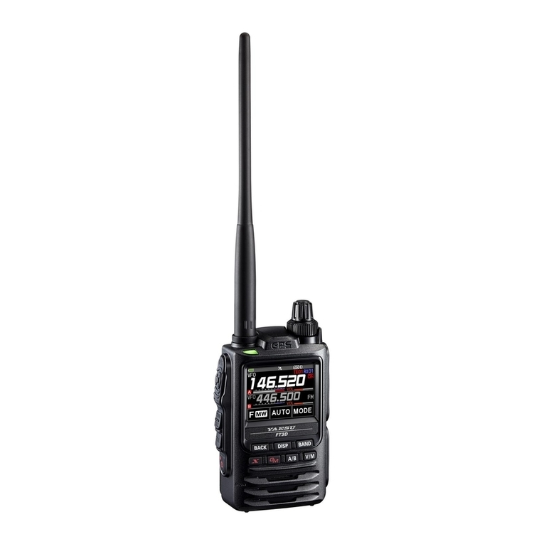
Yaesu FT3DR User manual

C4FM/FM 144/430MHz
DIGITAL/ANALOG TRANSCEIVER
FT3DR
Operating Manual

Quick Guide ....................................................3
Controls & Connections ................................4
Transceiver.......................................................................4
Touch Screen Display .....................................................6
Supplied Accessories and Options ..............9
Supplied Accessories......................................................9
Available Options.............................................................9
Preparation....................................................10
Installing the Antenna....................................................10
Attaching the Belt Clip...................................................10
Installing the Battery Pack ............................................10
Charging the Battery Pack...........................11
Charging the Battery Pack using the
Battery Charger (SAD-25B)..........................................11
Charging the Battery Pack using the
Rapid Charger (CD-41) .................................................11
External Power Supply.................................12
Connecting an External Power Supply for Use in
Vehicle............................................................................12
Connecting to an External Power Supply Using a
Power Cable...................................................................12
Using a microSD Memory Card...................12
Usable microSD Memory Cards ..................................12
Formatting a microSD Memory Card...........................12
Operation.......................................................13
Turning the Transceiver ON..........................................13
Adjusting the Volume Level...........................................13
Adjusting the squelch setting........................................13
Toggling the Operating Band........................................14
Selecting a Frequency Band.........................................14
Tuning to a Frequency...................................................14
Changing the Frequency Step.................................15
Selecting the Communication Mode............................16
Fixing the Communication Mode.............................17
Transmission..................................................................17
Changing the Transmission Power Level ....................18
Locking Keys and DIAL knob........................................18
Using the convenient Digital C4FM feature
..19
About the Digital Group ID (DG-ID) feature.................19
Communicating with the DG-ID feature.......................19
Repeater Operation......................................23
Communicating Via the Repeater................................23
Using the Memory ........................................24
Registering to Memory Channels.................................24
Recalling a Memory Channel.......................................24
Clearing Memories........................................................25
Restored erased memory.............................................25
Recalling the Home Channels......................................25
Changing the Home Channel Frequency....................25
Split Memory..................................................................26
Using Memory Tag ........................................................26
Using Memory Bank......................................................26
Scanning Function.......................................27
VFO Scan.......................................................................27
Memory Channel Scanning..........................................27
Programmable Memory scan (PMS)...........................28
Dual Receive (DW) feature...........................................28
Convenient Functions..................................29
Bluetooth®Operation.....................................................29
When connecting to a Bluetooth Headset for the
first time -Pairing-......................................................29
Hands-free operation with a Bluetooth headset
(VOX function)...........................................................30
Send by pressing the button on the Bluetooth
headset (when the VOX function is off)...................30
VOX Operation...............................................................31
Setting VOX function.................................................31
Set the VOX (automatic voice transmission)
delay time...................................................................31
Band Scope....................................................................32
GPS Function.................................................................33
Tone squelch feature.....................................................33
Digital Code squelch (DCS) feature.............................33
Digital Personal ID (DP-ID) feature..............................33
Using Set Mode.............................................34
Set Mode Operation......................................................34
Tables of Set Mode Operations...................35
Restoring to Defaults (Reset)......................41
All Reset .........................................................................41
Set Mode Reset.............................................................41
Specifications...............................................42
Contents

3
①Turning the Power ON
Install the charged battery pack and then
press and hold the switch.
②Inputting the Call sign
When turning the power ON for the first
time after purchasing, input the call sign of
your own station.
1. When turning the power ON for the first
time after purchasing, the call sign input
screen will be displayed.
2. Press the [DISP] key.
3. Input the call sign.
Rotate the DIAL knob to select each
character.
Touch to move the cursor to the
right.
4. Repeat step 3 to input the remaining
call sign characters.
Touch to move the cursor to the left.
5. Press the switch to conclude input-
ting.
Normal operation (VFO Mode) screen
will be displayed.
③Selecting the Operating Band
Press the [BAND] key.
④Tuning the frequency
Rotate the DIAL knob.
⑤Adjusting the volume
Rotate the VOL knob to adjust the volume
to a comfortable level.
⑥Adjusting the squelch setting
The squelch level may be adjusted to
mute the background noise when no sig-
nal is received.
1. Press the SQL switch.
2. Rotate the VOL knob to adjust the
squelch to a level at which the back-
ground noise is muted.
* When the squelch level is increased,
the noise is more likely to be si-
lenced, but it may become more diffi-
cult to receive weak signals.
3. Press the SQL switch to save the set-
ting.
⑦Selecting the
Communication Mode
The communication mode is automatically
selected to correspond to the signal being
received.
Touch [MODE] to manually select the com-
munication mode.
⑧
Transmitting/Receiving Signals
Transmitting
While pressing and holding the PTT ( )
switch, speak into the microphone.
Receiving
Release the to return to receive mode.
Quick Guide

4
Controls & Connections
Transceiver
①
②
③
④
⑤
⑥
⑦
⑧
⑨
⑩
⑪
⑫⑯
⑬
⑭
⑮
⑧
⑰
①GPS Antenna
②Antenna Jack (SMA)*
③TX/BUSY LED
Lights green (A-band) or blue (B-band)
during receive and lights red during trans-
mit.
④PTT Switch
Press and hold the PTT switch to transmit,
and release it to receive.
⑤MONI/T-CALL Switch
Press the MONI/T-CALL switch to open
the squelch.
⑥SQL Switch
Press the SQL switch, then rotate the VOL
knob to adjust the squelch level.
⑦Power (Lock) Switch
When the power is OFF, press and hold
this switch to turn the Power ON.
When the power is ON, press and hold
the switch again to turn the Power OFF.
When the power is ON, press this button
briefly to engage, or release the key lock.
⑧Battery Pack*
⑨Microphone
⑩DIAL knob
Rotate the DIAL Knob to change the fre-
quency or select a memory channel.
VOL knob
Rotate the VOL Knob to to adjust the audio
volume level.
⑪Full Color Touch screen display
Touch to set the frequency and various
other settings.
⑫Keypad
[BACK]
key
Press to return to the previous screen.
[DISP]
key
Pressing each time switches between the
frequency display and the backtrack dis-
play.
Press and hold for over one second to
enter Set mode.
[BAND]
key
Pressing each time increases the fre-
quency band.
[Ȥ]
key
In normal mode, press to start WIRES-X.
When WIRES-X is activated, press and
hold for over one second to return to the
normal mode.
[GM]
key
Press to turn the GM function on/off.
Press and hold for over one second to
enter DG-ID number setting screen.
[A/B]
key
Pressing each time switches between
A-band and B-band.
Press and hold for over one second to
switch between the Dual Band Receive
mode and the Mono Band Receive mode.
[V/M] key
Pressing each time switches between
VFO mode and memory mode.

5
⑬Speaker
⑭microSD memory card slot*
⑮DATA Terminal*
When updating the firmware, connect to a PC
using a USB cable.
⑯MIC/SP jack*
Connect the optional speaker microphone
or earpiece microphone to this jack.
When an external microphone or cable is
connected, the dust and splash protection
does not function.
Do not connect any microphone which
is not specified by Yaesu.
⑰EXT DC IN jack*
When charging the battery pack, connect
the battery charger (SAD-25B) to this
jack.
Connect an external power supply adapt-
er with a cigarette lighter plug (SDD-13)
or an external power cable (E-DC-6) to
this jack.
* When the included antenna and battery pack
are installed and the MIC/SP jack, DATA ter-
minal, micro SD card slot and EXT DC IN jack
are securely covered with rubber caps, the
FT3DR meets the waterproofing performance
conforming to IPX5.

6
Touch Screen Display
Battery condition
Displays mode
Squelch/Volume Bar Graph (B-band)
Displays operation mode
Squelch/Volume Bar Graph (B-band)
Display of settings such as DG-ID/TONE
Communication Mode
A-band display area
B-band display area
A-band icon
LOCK
Lights when the mute unction is active
Lights when Auto Power Off is active Lights when GPS is acquired
Lights when GPS Log Function is enabled
Lights when a microSD memory card is inserted
Lights when Bluetooth function is active
Lights when DTMF function is enabled
Communication mode selection (AMS/DN/VW)
Communication mode selection at AMS (AMS/DN/VW)
Press: Function menu screen
Press and hold: Memory write
B-band icon
Lights when AF DUAL Function is enabled
StatusBar
The battery condition is displayed in 8 steps.
: Full battery power
: Battery is depleted. Charge battery.
:
(When blinking) Charge battery immediately.
Appears when the lock function is enabled.
Appears when the Mute function is enabled.
Appears when the AF DUAL function is enabled.
Appears when the APO (Automatic Power-Off) function is enabled.
Appears when the DTMF Autodialer function is activated.
Appears when the Built-in GPS function is activated.
Appears when the Voice memory function is enabled.
Appears when the GPS Log function is enabled.
Appears when a microSD card is inserted.
Appears when the Bluetooth function is activated.

7
●Dual Band Screen
A-band and B-band are displayed in a top-down fashion.
●Function Menu Screen
Touching
[F MW]
displays the function menu screen.
Function Menu Screen 1 Function Menu Screen 2
●GPS Screen
The GPS satellite statuses are shown
with number.
●Band Scope Screen
The screen appears as shown, when the
band scope is turned on.
●SETUP MENU Screen
Set Mode allows selecting various functions from the list and setting each function ac-
cording individual preferences.

8
About Waterproofing Feature Conforming to IPX5
When the included antenna and battery pack are installed and the MIC/SP jack, EXT
DC IN jack, DATA terminal, and micro SD slot are securely covered with rubber caps,
this product is moisture and splash resistant. To ensure continued waterproofing pro-
tection, be sure to check the following points before use.
PCheck for damages, deterioration, and dirt.
Antenna rubber, key switch rubber, MIC/SP jack, EXT DC IN jack, DATA terminal, micro SD
slot rubber cap, and battery pack joint.
PCleaning
When this product is contaminated with seawater, sand, or dirt, rinse with fresh water, and
then wipe with a dry cloth immediately.
PRecommended maintenance interval
To insure continued water resistance and optimal performance, it is recommended that main-
tenance be performed annually, or when any damage or deterioration is found. Note that the
maintenance service is subject to fees.
PDo not immerse this product in the following liquids:
Sea, pool, hot spring, water containing soap, detergent, or bath additive, alcohol, or chemi-
cals.
PDo not leave this product for an extended time in the following places:
Bathroom, kitchen, or humid place
POther precautions
Since this product is not totally waterproof, it cannot be immersed in water.

9
Supplied Accessories and Options
Supplied Accessories
Rechargeable Li-Ion Battery Pack (7.2 V, 2,200 mAh) SBR-14LI
Battery Charger SAD-25B
Antenna
Belt Clip
USB Cable
Operating Manual (This Manual)
SBR-14LI Manual
Battery Pack protective cap
If any item is missing, contact the dealer from which you purchased the transceiver.
Available Options
Speaker / Microphone MH-34B4B
Earpiece Microphone SSM-57A
VOX Headset SSM-63A
Bluetooth®Headset SSM-BT10
Microphone Adapter CT-44
DC Cable with and Cigarette-Lighter Plug SDD-13
DC Cable E-DC-6
Soft Case SHC-34
3x “AA” Cell Battery Case FBA-39
Li-Ion Battery Packs (7.2 V, 2,200 mAh) SBR-24LI
Li-Ion Battery Packs (7.4 V, 1,100 mAh) FNB-101LI
Battery Charger SAD-25B
Rapid Charger CD-41
Speaker Microphone with Snapshot camera MH-85A11U
Cloning Cable CT-168
Data Cable CT-170
PC connection cable SCU-39
PC connection cable CT-169
Data cable (2.5) CT-176
Belt Clip SHB-13
BNC-to-SMAAdapter (BNCJ-SMAP) CN-3

10
Preparation
Installing the Antenna
1. Turn the antenna clockwise until it is secured.
Do not hold or twist the upper part of the antenna
when installing or removing it. To do so may break the
conductors inside the antenna.
Do not key the transmit without installing the antenna.
The transmitter components may be damaged.
Hold the thick base
of the antenna
Attaching the Belt Clip
1. Attach the belt clip on the back of transceiver using the
supplied screws (two).
Be sure to use the supplied screws when attaching the belt
clip. If any other screws are used, the belt clip cannot be
secured firmly to the battery pack and the transceiver may
drop off together with the battery pack; the transceiver and
battery pack may fall off, causing injury, breakage and other
damage.
Installing the Battery Pack
1. Insert the bottom tabs of the battery pack in the slots on
the back side lower part of the transceiver.
2. Push the battery in until the battery latches click
securely.
Charge the battery pack before using the transceiver for the
first time after purchase, or when it has not been used for a
long period time.
●Removing the Battery Pack
1. While pressing down the latches, remove the battery
pack.
Press the latches down in the direction of the arrows as
shown in the illustration.
Battery Latches

11
Charging the Battery Pack
Charging the Battery Pack using the Battery Charger (SAD-25B)
Using the supplied battery charger (SAD-25B), it takes about 9 hours* to charge the
SBR-14LI battery pack fully.
*Depending on the battery status, the charging time might be increased
1. Turn the transceiver OFF to install the battery pack.
2. Referring to the figure at the right, connect the
battery charger plugs.
When the battery is being charged, the TX/BUSY
Indicator lights red, and “CHGING” is dislapyed.
3. When charging is completed, the display will
change to indicate “CHGFUL” and the TX/BUSY
Indicator will light green.
EXT DC IN
jack
Battery charger
SAD-25B
(supplied)
When charging is completed, the charging is automatically ended.
If “CHGERR” appears on the LCD during the charging and the battery pack is not
charged after a lapse of 10 or more hours, stop charging the battery pack immediately.
The battery pack is presumed to be at the end of its service life, or defective. In this case,
replace the battery pack with a new one.
Charge the battery pack within the temperature range from +41°F to +95°F (+5°C to
+35°C).
Charging the Battery Pack using the Rapid Charger (CD-41)
For details on the Rapid Charger (CD-41), see Optional CD-41 manual
●Approximate Operating Time and Remaining Charge Level Indication
Approximate operating time for the transceiver with the fully charged battery pack or
new AA alkaline batteries is as follows:
Band in Use
Digital: OFF Battery pack
SBR-14LI Battery pack
FNB-101LI Battery
FBA-39
Amateur Band
144 MHz
Band Approx. 10 hours Approx. 5 hours Approx. 12 hours
430 MHz
Band Approx. 8.3 hours Approx. 4.1 hours Approx. 11 hours
AM Broadcast Band Approx. 20 hours Approx. 10 hours Approx. 14 hours
FM Broadcast Band Approx. 20 hours Approx. 10 hours Approx. 14 hours
Band in Use
Digital: ON Battery pack
SBR-14LI Battery pack
FNB-101LI Battery
FBA-39
Amateur Band
144 MHz
Band Approx. 8.8 hours Approx. 4.4 hours Approx. 12 hours
430 MHz
Band Approx. 7.6 hours Approx. 3.8 hours Approx. 11 hours
The battery charge level calculations are based on an operating cycle of: Transmitting 6
seconds (5 W): Receiving 6 seconds (VOL Level 16): Stand By 48 seconds (RX SAVE
1:5)
The actual times the transceiver will operate as indicated in the above table, varies de-
pending on use, conditions, ambient temperature, etc.

12
External Power Supply
Connecting an External Power Supply for Use in Vehicle
The optional DC Cable with Cigarette-Lighter plug (SDD-13) allows power to be supplied
from a motor vehicle type cigarette lighter socket.
Connecting to an External Power Supply Using a Power Cable
The optional DC cable (E-DC-6) allows the transceiver to be connected to an external
DC power supply.
Using a microSD Memory Card
Using a microSD memory card with the transceiver allows the following functions.
Backing up the transceiver data and information
Saving memory information
Saving GPS log data
Saving image data captured with the optional camera-equipped microphone (MH-
85A11U)
Saving messages downloaded with the GM function or WIRES-X function
Usable microSD Memory Cards
This transceiver only supports the following capacity of microSD and microSDHD mem-
ory cards.
・
2GB ・
4GB ・
8GB ・
16GB ・
32GB
microSD memory cards formatted on other devices may not properly save information
when used with this transceiver. Format microSD memory cards again with this transceiver
when using memory cards formatted with another device.
Do not remove the microSD memory card or turn the transceiver off, while saving data to
a microSD memory card is in progress.
Formatting a microSD Memory Card
Format a new microSD memory card following the steps below before use.
Formatting a microSD memory card erases all data saved on it. If you are going to format
the microSD memory card you are using, be sure to check the data saved on it before
formatting.
1. Press and hold the [DISP] key.
The “SETUP MENU” screen appears.
2. Touch [SD CARD].
3. Touch [4 FORMAT].
“FORMAT?” appears on the LCD.
4. Touch [OK].
Initialization starts and “Waiting” appears.
•To cancel formatting, select [CANCEL].
5. When formatting is completed, a beep sounds and “COMPLETED” appears on the
LCD.

13
Operation
Turning the Transceiver ON
1. Press and hold the Power (Lock) switch to turn the
transceiver ON.
●Inputting the call sign
The first time the transceiver is turned ON after it is
purchased; input your own call sign.
1. Press the [DISP] key to proceed to the call sign input
screen.
•When the transceiver is turned on the second time,
and subsequently, the opening screen appears fol-
lowed by the frequency screen.
2. Input the call sign (toggle the alphabet input screen,
and the number input screen when necessary).
3. Saving the inputted call sign:
4. Press the [PTT] switch or press and hold the [DISP]
key.
Up to 10 characters (letters, numbers, and symbols)
can be entered.
Characters that may be inputted for the call sign are
the numbers 0-9, letters ”A – Z” in upper case, the
hyphen and the slash.
Adjusting the Volume Level
1. Rotate the DIAL knob to adjust the volume to a com-
fortable level.
•The transceiver volume levels for the A-band and
B-band are adjusted separately.
Adjusting the squelch setting
The squelch level may be adjusted to mute the background noise when no signal is present.
1. Press the SQL switch and then rotate the VOL knob to adjust to a level at which the
background noise is muted.
appear on the display.
•The transceiver squelch levels for the A-band and B-band are adjusted separately.
The default setting is “1”.
When the squelch level is increased, the noise is more likely to be silenced, but it may
become more difficult to receive weak signals.
2. Press the SQL switch to save the setting.

14
Toggling the Operating Band
Normally, both operating bands are displayed on the top
half and bottom half of the transceiver touch screen. This
is Dual band.
With one of the bands selected, change the frequency and
radio operating mode.
•The selected band (displayed in white letters) is called
Operating band.
•The other band (displayed in gray letters) is called Sub-
band.
•Each time pressing the [A/B] key toggles the operating
band.
•The desired operating band may also be selected by
touching the frequency display.
Pressing and hold the [A/B] key displays only the operating
band, this is Mono-band.
Selecting a Frequency Band
1. Press the [BAND] key to select the desired fre-
quency band.
•Press the [F MW] key, then press the [BAND] key
to switch the frequency bands in reverse order.
Tuning to a Frequency
●DIAL knob
By pressing the
[F MW]
key and then rotating the
DIAL knob, the frequency will change in 1 MHz steps.

15
●The numeric keys
1. Touch the frequency displayed on the LCD.
The numeric keypad appears.
2. Enter the frequency using the numeric keys.
Example: To input 145.520 MHz
[1]
ĺ
[4]
ĺ
[5]
ĺ
[5]
ĺ
[2]
Example: To input 430.000 MHz
[4]
ĺ
[3]
ĺ
[ENT]
When entering a frequency using the numeric keys,
it may be canceled by pressing the PTT switch or the
[BACK] key.
Changing the Frequency Step
The DIAL knob rotation frequency step may be changed. Normally, the factory default
setting will provide a good frequency step.
1. Press and hold the [DISP] key, then touch [CONFIG].
2. Touch [18 STEP] then rotate the DIAL knob to change the frequency step.
3. Press the PTT switch to save the setting and return to normal operation.
In the default setting, of the frequency step is set to “AUTO”, which automatically provides
a suitable frequency step according to the frequency band.

16
Selecting the Communication Mode
●Using AMS
The FT3DR transceiver is equipped with the AMS (Auto-
matic Mode Select) function which automatically selects
the communication mode corresponding to the received
signal.
To utilize the AMS function, touch [MODE] to display
“”* on the display. After receiving the signal, “FM” of
“” will be changed according to the received signal.
*The display differs depending on the received signal.
●Setting the transmission mode when using the
AMS function
The AMS function will automatically set the receiver to
the mode of the received signal, but the transmission
mode may be fixed regardless of the received mode.
1. Touch [AUTO]* to tune to the desired transmission
mode as follows.
*The display differs depending on the transmission
mode.
Transmit Mode Receive and Transmit
AUTO
(default)
5HFHLYHʟAutomatically selects the communication mode of transmission according
to the signal being received.
Transmit:Transmits automatically in the communication mode selected by theAMS
function.
TX FM 5HFHLYHʟAutomatically selects the communication mode of transmission according
to the signal being received.
Transmit:Always transmits in the analog FM mode.
TX DN
(TX DIGITAL)
5HFHLYHʟAutomatically selects the communication mode of transmission according
to the signal being received.
7UDQVPLWʟAlways transmits in the DN mode.

17
Fixing the Communication Mode
1. To fix the transmission mode for operation, touch
[MODE] to switch the communication mode.
Communication Mode Icon Description of Modes
V/D Mode
(Voice/Data simultaneous trans-
mission mode)
This is the standard digital mode.
Calls are less prone to interruptions caused by detec-
tion and correction of the received digital voice signal.
Voice FR Mode*1
(Voice Full Rate Mode)
*1High speed data communication using entire 12.5 kHz
band.
Enables high-quality voice communication.
FM Mode Analog communication using FM mode.
AM Mode (receive only)*2The AM mode for receive only.
*1 When the Set Mode [TX/RX] £[2 DIGITAL] £[4 DIGITAL VW] is set to “ON” (factory
default is “OFF”), the Voice FR mode (VW) may be selected.
*2 When the Set Mode [TX/RX] £[1 MODE] £[3 RX MODE] is set to “AUTO” (factory
default setting), AM mode is automatically selected within the AIR band (108 -
136.995 MHz).
Transmission
1. While pressing and holding the PTT switch, speak
into the microphone.
The TX/BUSY indicator will glow red during transmis-
sion.
If the PTT switch is pressed when a frequency other
than the amateur ham radio band is selected, an alarm
tone (beep) will be emitted and “ERROR” appears on
the LCD, disabling transmission.
2. Release the PTT switch to return to receive mode.
When receiving a signal, the TX/BUSY Indicator
lights according to the receive mode.
Receive Band
TX/BUSY LED
A-band receiving Green
B-band receiving Blue
Receiving A and B
simultaneously Light Blue
MIC
TX/BUSY LED
If transmission is continued for a long period, the transceiver overheats and the high
temperature protection function is activated. As a result, the transmitting power level is
automatically set to Low Power. If transmission continues while the high temperature
protection function is active, the transceiver will be forcibly returned to the receive mode.

18
Changing the Transmission Power Level
1. Touch [F MW], then touch [TX PWR].
2. Rotate the DIAL knob to select one of the following
transmission power levels.
TX PO Level PO Meter
HIGH (5 W)*
LOW3 (2.5 W)
LOW2 (1 W)
LOW1 (0.1 W)
*The default setting.
3. Press the PTT switch to save the setting and return to the normal operation.
The transmission power level may be set separately for each frequency band.
Locking Keys and DIAL knob
1. Press the Power (Lock) switch, “LOCK” is displayed
on the display for one second, the “ ” icon appears
on the LCD, and then the keys and DIAL knob are
locked.
The keys, the DIAL knob, and the PTT switch may be selected to be locked using Set
Mode [CONFIG] £[9 LOCK]. The default setting is the “KEY&DIAL” (the keys and the
DIAL knob are locked).
The MONI/T-CALL switch, SQL switch and the VOL knob cannot be locked.
2. Press the POWER (Lock) switch again, “UNLOCK” will be displayed on the Display
and keys and the DIAL knob are unlocked.

19
Using the convenient Digital C4FM feature
About the Digital Group ID (DG-ID) feature
1. Digital Group ID (DG-ID) function allows communications with only the specific group
members using the two-digit ID numbers. The desired DG-ID number from 00 to 99
is set in advance by all the group members. This ID number may be set separately
for transmit and receive, when the same ID number is set for both transmit and re-
ceive, only group members with the same ID number will be heard. This feature may
be used to communicate only with group members that have the same DG-ID num-
ber. The GM function may also be utilized to automatically monitor whether or not
group member stations with the same DG-ID number are operating within communi-
cation range.
The DG-ID number 00 detects signals with all ID numbers. Normally setting the ID
number to “00” for both transmit and receive will permit reception of the signals from
all other stations using the digital C4FM mode, regardless of the transmit DG-ID
number settings of the other stations.
Also note that when the receive DG-ID number of your transceiver is set to a DG-ID
number other than “00”, received signals that do not have the same DG-ID number
may not be heard.
2. When accessing the C4FM digital repeater controlled by the DG-ID number, set the
transmit DG-ID number of the FT3DR to that of the repeater input. Even in that case,
if the receive DG-ID number of the FT3DR is set to “00”, all the downlink signals from
the repeater may be received.
Communicating with the DG-ID feature
Digital C4FM mode transceivers compatible with the DG-ID function are required in order
to utilize this function.
If the firmware is not compatible with the DG-ID function, update the latest firmware to use
the DG-ID function. The latest firmware is available on the YAESU website.
Setting the transmit and receive DG-ID number to “00” for communicating
with all other stations using C4FM digital mode
1. Press and hold the [GM] key.
The DG-ID number setting screen will be displayed.
If the transmit DG-ID (DG-ID TX) number is not set to
“00”, press the [GM] key then rotate the DIAL knob to
set “00”.
'*,'7;
'*,'5;

20
2. Press the [GM] key again to select the receive DG-ID
(DG-ID RX).
If the receive DG-ID number is not set “00”, press the
[GM] key then rotate the DIAL knob to set “00”.
'*,'7;
'*,'5;
3. Press and hold the [GM] key, or press the PTT switch to save the setting and return
to the normal operation.
The setting is complete.
4. To check whether or not other stations are operating within communications range,
press the [GM] key to turn the GM (Group Monitor) function ON.
•The other stations also need to turn the GM (Group Monitor) function ON.
5. Press the [GM] key to turn the GM (Group Monitor) function OFF and return to the
normal operation.
While setting the DG-ID number, pressing and holding the [DISP] key will set the transmit
and the receive DG-ID numbers to “00”.
If the receive DG-ID is set to a number other than “00”, only signals with that DG-ID will
be received. Normally, set the receive DG-ID number to “00” except when communication
is desired only with group members.
The transmit and receive DG-ID default number is set to “00”.
Communicating only with the specific members by setting the DG-ID number
except for “00”
Example: Set the DG-ID number of to “50”
1. Press and hold the [GM] key.
The DG-ID number setting screen will be displayed. '*,'7;
'*,'5;
2. Press the [GM] key, then rotate the DIAL knob to set
the transmit DG-ID (DG-ID TX) to “50”. '*,'7;
'*,'5;
Other manuals for FT3DR
6
Table of contents
Other Yaesu Transceiver manuals

Yaesu
Yaesu FTDX1200 Series Owner's manual

Yaesu
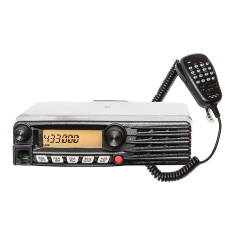
Yaesu FTM-400DR Use and care manual

Yaesu
Yaesu FT-8800R User manual

Yaesu
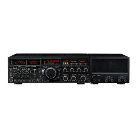
Yaesu FTDX-9000D General instructions

Yaesu
Yaesu VX-3R Manual

Yaesu
Yaesu FT-107M User manual

Yaesu
Yaesu FT-1500M User manual

Yaesu
Yaesu FTM-350 - APRS User manual

Yaesu
Yaesu FT-857D User manual

Yaesu
Yaesu FTM-10R Manual

Yaesu
Yaesu VX-8DR User manual

Yaesu
Yaesu FT-847 User manual

Yaesu
Yaesu FT-817 - User manual

Yaesu
Yaesu FTM-350R - SOFTWARE UPDATE PROCEDURE 7110 User manual

Yaesu
Yaesu 600 User manual

Yaesu
Yaesu FT-2000 - MENU MODE LIST User manual

Yaesu
Yaesu FT-107M Manual

Yaesu
Yaesu FT-50R Manual

Yaesu
Yaesu FT-5100 Manual

Yaesu
Yaesu FT-80C - SERVICE User manual