Revision 1.00 beta –April 2019
5
4 common lines
Polarizer type –transflective
USB UART interface
FTDI chipset. Speed 9600 - 56300bps
Receiver
Sensitivity (MDS) -135dBm (preamplifier On; VBF filter 2)
- -129dBm (preamplifier Off; VBF filter 2)
Selectivity Crystal 8 pole 2.7kHz first roofing filter at 9MHz
0.2-2.7kHz second variable filter Johnson type 9MHz
Crystal 2-pole IF noise filter 9MHz
Dynamic range Two tones close spaced (2kHz):
96db (Preamplifier On; VBF filter 2)
99db (Preamplifier Off;VBF filter 2)
Audio 2W at 8 ohms internal speaker
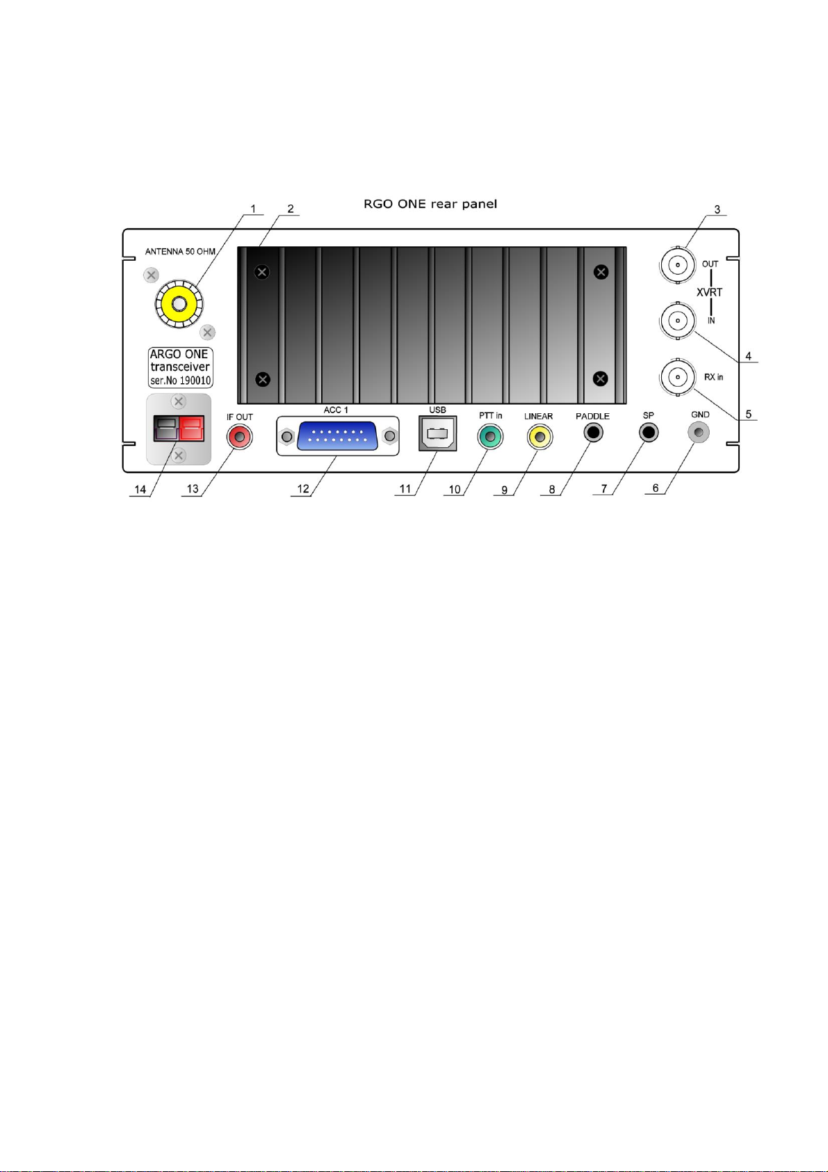
Rear panel 3.5mm (1/8”) jack for external speaker
Front panel jack 3.5mm (1/8”) for headphones 8 – 32 ohms
IF frequency 9MHz (Other frequencies can be used. Firmware calculate
LO&BFO frequencies)
Crystal filters Three type of filters are used –First roofing filter –8 pole 9MHz;
second (optional) 4 pole variable bandwith filter Johnson type
9MHz; third 2 pole noise filter 9MHz
Noise Blanker NB is optional plug-in accessory. IF type. 50db blanking range
Audio Filter AF is optional plug-in accessory. Follows selected bandwith
Transmitter
Power output 50W on CW; 40W PEP on SSB.
Adjustable output 5 –50W by steps of 1W
T/R switching Clickless quiet diode switching. PTT/VOX on SSB
QSK/Delay (10ms –1.2s) on CW
CW sidetone Internally generated –Pure sinusoidal signal formed same
manner as the CW signal. Adjustable frequency (400-800Hz) and
volume independent from AF volume
SSB method Balanced modulator with suppressed carrier, 2.7kHz ladder type
8 pole crystal filter (Same filter used on RX). Tracking ALC
scheme holds the PEP power in assigned limits
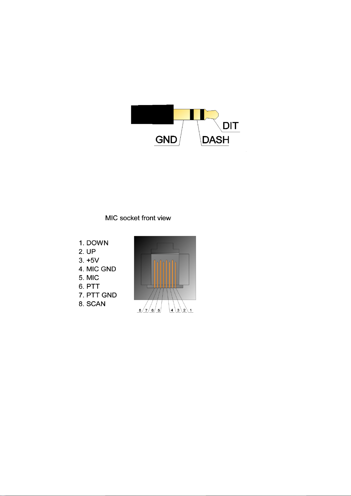
Microphone Standard electret microphone with bias
Carrier suppression
45dB minimum
Sideband suppression
50db minimum
Spurious products
less than -47dBc
Harmonic content
less than -45dBc
Intermodulation distortion IMD3 products on SSB @ 40W
-29dBc on 28MHz
-31dBc on 14MHz
Duty cycle 50W - 50%; 20W –100% (with optional fan cradle)