Yaesu VXA-200 User manual

Operating Manual

CONTENTS
Important Notice! .............................................. 1
Introduction....................................................... 2
Controls & Connectors ..................................... 3
Top Panel ....................................................................3
LCD Display...............................................................4
Front Panel ..................................................................5
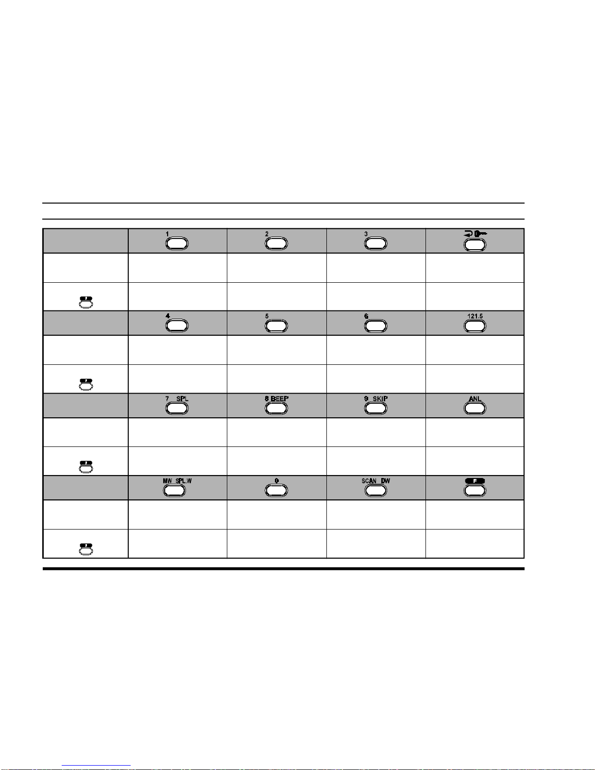
Keypad ........................................................................6
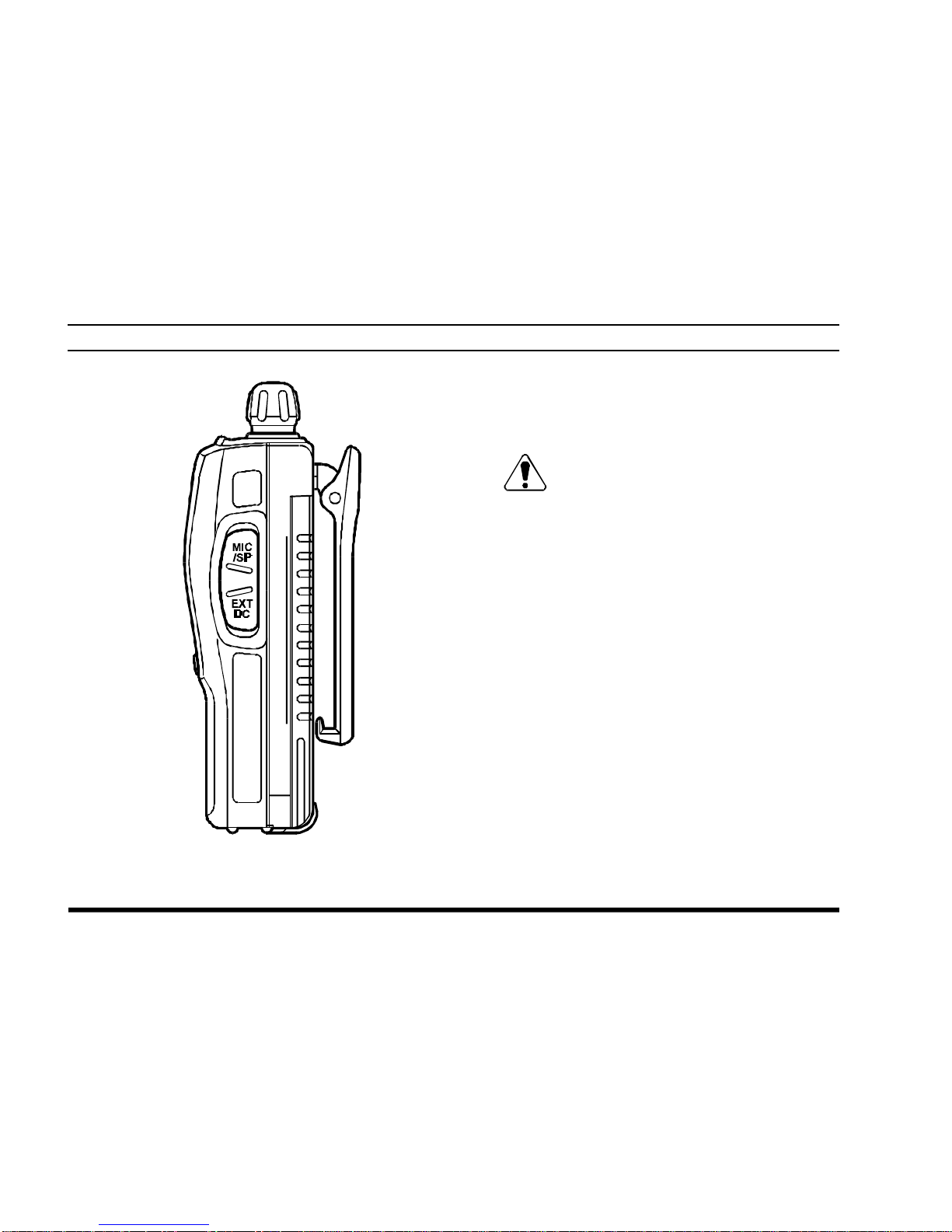
Left Side ......................................................................7
Right Side ...................................................................8
Before You Begin .............................................. 9
Precaution ...................................................................9
Battery Installation and Removal ..............................9
Battery Charging.......................................................10
Low Battery Indication ............................................11
Installing the FBA-25 (option)
Alkaline Battery Case.........................................11
Operation......................................................... 12
Preliminary Steps......................................................12
Operation Quick Start ..............................................12
Accessing the 121.5 MHz
Emergency Frequency..............................................14
Tuning Methods........................................................15
Transmission ............................................................ 16
Reception of Weather Channel Broadcasts ............ 16
Monitor Key............................................................. 18
ANL (Automatic Noise Limiter) Feature ............... 18
LOCK Function ....................................................... 19
Beep On/Off............................................................. 19
Receive Battery Saver Setup................................... 20
Memory Operation........................................... 21
Memory Storage ...................................................... 21
Recalling the Memories .......................................... 22
ScanningOperation ........................................ 23
Channel-Skip Scanning ........................................... 24
Dual Watch Operation ..................................... 25
Priority Dual Watch Operation ........................ 26
Split Operation ................................................ 27
Programming a Transmit Frequency ...................... 27
Operating in the Split Mode.................................... 27
Field Programming Mode................................ 28
Memory Storage into the Book Memory ............... 28
Menu (“Set”) Mode.......................................... 29
Menu Listing ............................................................ 30
Specifications.................................................. 33
Accessories & Options ................................... 34
NOTICE
There are no user-serviceable points inside this transceiver.
All service jobs must be referred to your Authorized Service Center.

VXA-200 AVIATOR PILOT II OPERATING MANUAL 1
IMPORTANT NOTICE!
FCC RF Exposure Compliance Requirements for Occupational Use Only:
This Radio has been tested and complies with the Federal Communications Commission (FCC) RF exposure
limits for Occupational Use/Controlled exposure environment. In addition, it complies with the following Stan-
dards and Guidelines:
rFCC 96-326, Guidelines for Evaluating the Environmental Effects of Radio-Frequency Radiation.
rFCC OET Bulletin 65 Edition 97-01 (1997) Supplement C, Evaluating Compliance with FCC Guidelines
for Human Exposure to Radio Frequency Electromagnetic Fields.
rANSI/IEEE C95.1-1992, IEEE Standard for Safety Levels with Respect to Human Exposure to Radio
Frequency Electromagnetic Fields, 3 kHz to 300 GHz.
rANSI/IEEE C95.3-1992, IEEE Recommended Practice for the Measurement of Potentially Hazardous Elec-
tromagnetic Fields - RF and Microwave.
¦This radio is NOT approved for use by the general population in an uncontrolled environment. This
radio is restricted to occupational use, work related operations only where the radio operator must
have the knowledge to control its RF exposure conditions.
¦When transmitting, hold the radio in a vertical position with its microphone 1 to 2 inches (2.5 to 5 cm)
away from your mouth and keep the antenna at least 1 inch (2.5 cm) away from your head and body.
¦The radio must be used with a maximum operating duty cycle not exceeding 50%, in typical Push-to-
Talk configurations.
DO NOT transmit for more than 50% of total radio use time (50% duty cycle). Transmitting more
than 50% of the time can cause FCC RF exposure compliance requirements to be exceeded.
The radio is transmitting when the red LED on the top of the radio is illuminated. You can cause the
radio to transmit by pressing the P-T-T button.
¦Always use Vertex Standard authorized accessories.

VXA-200 AVIATOR PILOT II OPERATING MANUAL
2
INTRODUCTION
The Yaesu VXA-200 Aviator Pilot II is a compact, stylish, solid hand-held transceiver providing communica-
tion (transmit and receive) capability on the International Aircraft Communication Band (“
COM
” band: 118 ~
136.975 MHz), and it additionally provides VOR and CDI navigation features on the “
NAV
” band (108 ~
117.975 MHz).
The VXA-200 includes Temperature display with our exclusive Omni-GlowTM display back-light for minimal
degradation of your night vision, NOAA weather band monitoring, 8-character Alpha/Numeric Display, 50
Memory Channels, and 100 “Book Memory” Channels. And the optional Barometric Pressure Unit (SU-1)
provides readout of barometric pressure, altitude, and density altitude.
We recommend that you read this manual in its entirety, so as to understand the many features of the VXA-200
completely. Keep this manual handy, so you may use it for reference.
NOTE: The VXA-200’s VOR and CDI Navigation features are supplemental aids to navigation only, and are
not intended to be a substitute for accurate (primary) VOR/CDI or landing service equipment. And also, the
Barometric/Altitude features of the optional SU-1 are designed to be a substitute for accurate, calibrated Ba-
rometer or Altimeter devices used for navigation critical to personal safety.
Congratulations!
You now have at your fingertips a valuable communications tool-a YAESU two-way radio! Rugged,
reliable and easy to use, your YAESU radio will keep you in constant touch with your colleagues for
years to come, with negligible maintenance down-time.
Please take a few minutes to read this manual carefully. The information presented here will allow you to
derive maximum performance from your radio, in case questions arise later on.
We're glad you joined the YAESU team. Call on us anytime, because communications is our business.
Let us help you get your message across.

VXA-200 AVIATOR PILOT II OPERATING MANUAL 3
CONTROLS & CONNECTORS (TOP PANEL)
①Antenna Jack
This SMA jack accepts the supplied flexible an-
tenna, or another antenna designed to provide 50
Ωimpedance on the Aircraft Communication
Band.
②POWER/VOLUME Knob
Turn this control clockwise to turn the radio on
and to increase the volume. Counterclockwise ro-
tation into the click-stop will turn the radio off.
③CHANNEL Selector Knob
This 20-position detended rotary switch tunes the
operating frequency or selects the memory chan-
nels.
Pressing this knob momentarily selects the tun-
ing methods among the VFO (Variable Fre-
quency Oscillator), MR (Memory Recall),
BOOK (Pre-Programmed Memories), and WX
(Weather Channel Memories) mode.
Note: The WX mode is activating the USA ver-
siononly.
④BUSY/TXIndicator Lamp
This lamp glows green when a signal is being
received and red when transmitting.

VXA-200 AVIATOR PILOT II OPERATING MANUAL
4
CONTROLS & CONNECTORS (FRONT PANEL)
⑤LCD (Liquid Crystal Display)
The display shows the selected operating condi-
tions as indicated on the next page.
⑥Loudspeaker
The internal speaker is located in this position.
⑦Microphone
Speak across this opening in a normal voice level
while pressing the PTT switch.
⑧Keypad
Several keys have dual functions.
The primary functions are labeled on the key top
(activated by simply pressing the key momen-
tarily), while the secondary functions are labeled
to along with the top edge of the key (activated
by pressing the [F]key first, then the indicated
key).
These functions are described in detail on page 5.
⑨Battery Pack Latch
Open this latch for battery removal.

VXA-200 AVIATOR PILOT II OPERATING MANUAL 5
CONTROLS & CONNECTORS (LCD DISPLAY)
This field displays the course
headingindegrees.See page25. This is the Course Deviation Indicator, used
during VOR Navigation. See page 24.
This icon indicates that
the “Book” Memory Bank
is in use. See page 12.
This icon is the “Low Bat-
tery” indicator, which
blinks when the battery
voltage becomes too low
for proper operation. Thesedigitsprovidefrequencyoralphanumeric
information about the channel you are using.
This indicator confirms
thatSecondary KeyFunc-
tion is active. See page 4.
This icon is used
during VOR naviga-
tion, to indicate that
the displayed infor-
mation is based on
a course from the
VOR station. See
page25.
This icon is used
during VOR naviga-
tion, to indicate that
the displayed infor-
mation is based on
a courseto theVOR
station. See page
25.
This indicator con-
firms that the AUTO-
MATIC NOISE LIMITER is
activated.Seepage
15.
This indicator con-
firms that the “Split”
(Duplex) mode is
activated during
VORoperation.See
page30.
This indicator con-
firms that DUAL
WATCH isactive.See
page22.
This indicator confirms
that this channel will be
skipped during scan. See
page21.

VXA-200 AVIATOR PILOT II OPERATING MANUAL
6
CONTROLS & CONNECTORS (KEYPAD)
Primary Function
(PressKey)
Secondary Function
(Press +)
Primary Function
(Press Key)
Primary Function
(Press Key)
Primary Function
(Press Key)
Frequency Entry
Digit 1 Frequency Entry
Digit 2 Frequency Entry
Digit 3
Frequency Entry
Digit 4 Frequency Entry
Digit 5 Frequency Entry
Digit 6
Frequency Entry
Digit 7 Frequency Entry
Digit 8 Frequency Entry
Digit 9
Frequency Entry
Digit 0
Selects Memory Display
Type (page 19)
LockstheKeypad
SelectsEmergency
Channel (121.5 MHz)
Display the Density
Altitude (requires SU-1)Display the current
Temperature None
None
NoneNone
Activates Automatic
NoiseLimiter
Activates Split (Duplex)
mode On/OffSwitch
forKeypadBeeper AllowsSkippingof
Channel during Scan
Activates Scanning Activates“Secondary”
Keymode
Activates Dual Watch
Memory“Write”
Command
Split-Memory“Write”
Command
Secondary Function
(Press +)
Secondary Function
(Press +)
Secondary Function
(Press +)
Selects
“FROM”VORmode
Selects
“TO”VORmode
ActivatesDVORmode
Activates Course
Direction Indicator mode

VXA-200 AVIATOR PILOT II OPERATING MANUAL 7
⑩PTT (PUSH TOTALK)Switch
Press this button to transmit when you are oper-
ating in the “
COM
” band. Release this button to
return to the “RECEIVE” mode. See page 15.
⑪MONITOR Switch
This button may be pressed to “open” the squelch
manually, allowing you to listen for very weak
signals. Press and hold this button for 2 seconds
to “open” the squelch continuously. Press this
button again to resume normal (quiet) monitor-
ing. See page 12.
⑫LAMP Switch
Press this switch momentarily to activate the
back-lightinglampforthedisplay.Pressandhold
this switch for 2 seconds to activate the back-
lighting lamp continuously. To turn the lamp off,
press this switch again. The LAMP switch may
be configured in several ways via the Menu; see
page 28 for details.
CONTROLS & CONNECTORS (LEFT SIDE)

VXA-200 AVIATOR PILOT II OPERATING MANUAL
8
CONTROLS & CONNECTORS (RIGHT SIDE)
⑬MIC/EAR Jack
You may connect the supplied CT-60 Headset
Cable or the (optional) MH-44A4B Speaker/Mi-
crophone to this jack.
Never connect any Speaker/Microphone
that is not recommended by the manufac-
turer. Because these jack connections are unique,
using a Speaker/Microphone that is not specified
by Yaesu may damage the VXA-200.
⑭EXT DC Jack
When an external 12-Volt DC power source is
available, you may connect the (optional)E-DC-
5B External DC Cable here. Do not connect any
wire to this jack if that wire is connected di-
rectly to a 28-Volt DC source. Connecting the
VXA-200 directly to a source which exceeds 15.0
Volts DC will result in damage to the unit.

VXA-200 AVIATOR PILOT II OPERATING MANUAL 9
BEFORE YOU BEGIN
Precautions
rThis apparatus is capable of two-way communi-
cation on channels used for critical aviation safety
communications. Therefore, it is important that
this radio be kept away from children or other
unauthorized users at all times.
rWhen making DC connections via the (optional)
E-DC-5B DC cable, be absolutely certain to
observe the proper voltage level and polarity
guidelines. Do not connect this radio directly to
any 24 ~ 28 Volt DC source, nor to AC power of
any kind. Connecting the VXA-200 directly to a
source which exceeds 15.0 Volts DC will result
in damage to the unit.
rDo not dispose of the Ni-Cd Battery Pack in a
fire. Do not carry a Ni-Cd Battery Pack in your
pocket, where keys or coins could short the ter-
minals. This could create a serious fire/burn dan-
ger, and possibly cause damage to the Ni-Cd
pack.
rAlthough the VXA-200 is designed to be water
resistant, the enclosure is not “waterproof.” Do
not allow the radio to become submersed in wa-
ter, and do not expose it and/or its Ni-Cd Battery
Pack to water spray under pressure.
Battery Installation and Removal
¦To install the battery, hold the transceiver with
your left hand, so your palm is over the speaker
and your thumb is on the top of the Belt Clip.
Insert the battery pack into the battery compart-
ment on the back of the radio while tilting the
Belt Clip outward, then close the Battery Pack
Latch until it locks in place with a “Click.”
¦To remove the battery, turn the radio off and re-
move any protective cases. Open the Battery Pack
Latch on the bottom of the radio, then slide the
battery downward and out from the radio while
unfolding the Belt Clip.
Do not attempt to open any of the recharge-
able Ni-Cd packs, as personal injury or dam-
age to the Ni-Cd pack could occur if a cell or cells
become accidentally short-circuited.

VXA-200 AVIATOR PILOT II OPERATING MANUAL
10
the charger/battery. Contact your Dealer if you
have any doubts about the appropriateness of the
particular charger or battery pack you intend to
use.
BEFORE YOU BEGIN
Battery Charging
It is necessary to fully charge the Ni-Cd battery be-
fore its first use. Follow these procedures:
¦Install the supplied FNB-64 Ni-Cd battery pack
onto the transceiver. Ensure that the transceiver
is switched off.
¦Plug the NC-77 into the AC line outlet.
¦Insert the battery pack into the NC-77; the an-
tenna jack should be at the left side when view-
ing the charger from the front.
¦If the battery pack is inserted correctly, the RED
indicator will glow. A fully-discharged pack will
be charged completely in 15 hours.
Important Notes:
rThe NC-77 is not designed to power the trans-
ceiver for operation (reception or transmission).
rDo not leave the charger connected to the trans-
ceiver for continuous periods in excess of 24
hours. Long term overcharging can degrade the
Ni-Cd battery pack and significantly shorten its
useful life.
rIf using a charger other than the NC-77, or if
using a battery pack other than the FNB-64, fol-
low the appropriate instructions provided with VXA-200/NC-77

VXA-200 AVIATOR PILOT II OPERATING MANUAL 11
Low Battery Indication
¦As your battery discharges during use, the volt-
age will gradually become lower. When the bat-
tery voltage reaches 6.0 Volts, the “x” icon
will blink on the LCD display, indicating that
the battery pack must be recharged before fur-
ther use.
¦Avoid recharging Ni-Cd batteries before the
“Low Battery” indicator is observed, as this can
degrade the charge capacity of your Ni-Cd bat-
tery pack. Yaesu recommends that you carry an
extra, fully-charged pack with you so you will
not lose communications capability due to a de-
pleted Ni-Cd battery.
This “deep cycling” practice will help to main-
tainlonger overall battery lifeaftermanyrecharg-
ing cycles.
BEFORE YOU BEGIN
Installing the FBA-25 (option) Alkaline
Battery Case
The optional FBA-25 Battery Case allows opera-
tion of the VXA-200 using six “AA” size Alkaline
batteries.
When installing batteries, insert the (–) end first, then
press in the (+) end so the battery snaps into place.
Always replace all six batteries at the same time, pay-
ing attention to the polarity indicated inside the case.
The FBA-25 must not be used with re-
chargeable cells. The FBA-25 does not con-
tain the thermal and over-current protection cir-
cuits (provided in the “FNB” series of Ni-Cd Bat-
tery Packs) required when utilizing Ni-Cd cells.

VXA-200 AVIATOR PILOT II OPERATING MANUAL
12
OPERATION
PreliminarySteps
¦Installa charged battery packontothetransceiver,
as described previously.
¦Screw the supplied antenna onto the Antenna
jack. Never operate this transceiver without an
antenna connected.
¦If you have an optional Speaker/Microphone or
headset, we recommend that it not be connected
until you are familiar with the basic operation of
the VXA-200.
Operation Quick Start
rTo turn the radio on,
rotate the VOLUME
knob out of the click-
stop.
rAfter three “initial-
ization” beeps are
heard, a channel fre-
quency should ap-
pearonthedisplay.If
not, press downward
(momentarily)onthe
CHANNEL selector knob (repeatedly, if neces-
sary) so that “"VFO "” appears on the display,
followed by a channel frequency.
rDirectly entering frequencies from the Keypad
is the easiest method if you know the frequency
on which you wish to operate. Just enter the five
digits of the frequency to move to that frequency.
For example, to set 134.35 MHz,
press [1]à[3]à[4]à[3]à[5].

VXA-200 AVIATOR PILOT II OPERATING MANUAL 13
To set 118.275 MHz, you do not need to press
the final “5” in the frequency:
[1]à[1]à[8]à[2]à[7].
rYou may also turn
the top panel’s
CHANNEL selector
knob to choose the
desiredoperatingfre-
quency. The channel
frequency will ap-
pear on the LCD.
rTo change frequency
in 1 MHz steps, press
the [F]key momen-
tarily, then rotate the
CHANNEL selector
knob to select the
MHz digit desired.
Press [F]once more to resume normal channel
selection in 25-kHz steps.
OPERATION
rRotate the VOL-
UME knob to set the
volume level. If no
signal is present,
press and hold the
MONITOR button
for 2 seconds; back-
ground noise will
now be heard, and
you may use this
noise to set the VOL-
UME knob for the
desired audio level.
Press theMONITOR
button momentarily to silence the noise and re-
sume normal (quiet) monitoring.
rPress and hold the
LAMP button for 2
seconds, to illumi-
nate the display con-
tinuously. To disable
the illumination,
press the LAMPbut-
ton momentarily.

VXA-200 AVIATOR PILOT II OPERATING MANUAL
14
rTo turn the radio off,
turn the VOLUME
knob fully counter-
clockwise into the
click stop position.
OPERATION
Accessing the 121.5 MHz Emergency Frequency
The VXA-200 can quickly access the 121.500 MHz
Emergency Frequency. This function can be activated
even when the keypad lock function is in use.
rTo access the Emer-
gency Frequency,
press the [121.5]key
momentarily.
rTo exit the Emer-
gency Frequency,
press the CHAN-
NEL selector knob.

VXA-200 AVIATOR PILOT II OPERATING MANUAL 15
Tuning Methods
Throughout this manual, you will see references to
several different frequency setting methods. Each will
be particularly useful in a particular operating situa-
tion, and they are described below:
¦VFO (Variable Frequency Oscillator)
The VFO is a “tuning
dial” system which al-
lows you to tune through
the
NAV
or
COM
bands
in 25-kHz steps using the CHANNEL selector,
the Keypad, or the scanner.
¦MR (Memory Recall)
The MR (Memory Re-
call) mode of the VXA-
200 provides the user
with the ability to store
and recall as many as 50 channels in the radio’s
main memory bank. These memory channels may
also be labeled by you with an alpha/numeric
name of up to 8 characters in length, to aid in
quick identification of the channel. See page 20
for details on creating alpha/numeric labels.
¦BOOK (Pre-Programmed) Memories
The Book memories are
pre-programmed,eitherat
the factory or by your
Dealer (depending on
your country’s requirements), typically including
the major
COM
and
NAV
band station frequen-
cies used in your area. The Book memories can
be changed by the user. See page 27 for details.
¦WX (Weather Channel) Memories
(USA version only)
Ten Weather Channels
are pre-programmed at
the factory as appropriate
for your country, and the VXA-200 will auto-
matically scan this special bank when it is se-
lected by the user.
OPERATION

VXA-200 AVIATOR PILOT II OPERATING MANUAL
16
Transmission
To transmit, press and
hold the PTT switch.
Speak into the micro-
phone area of the front
panel grille in a normal
voice level.
To return to the receive
mode, release the PTT switch.
Reception of Weather Channel Broadcasts
(USA version only)
The VXA-200 can receive VHF Weather Channel
broadcasts, which may assist your flight planning.
The VXA-200 includes a ten-channel auto-search
feature, which simplifies access to Weather Chan-
nels when you are in an unfamiliar location.
rTo receive Weather
Channels, press the
CHANNEL selector
knob (repeatedly, if
necessary)toselectthe
Weather Channel
mode. In the Weather
Channel mode, “"WX"
”willappearonthedisplay.
rThe VXA-200 will now scan quickly through the
ten standard Weather Channels, and will stop on
the first active station found.
rIf there are two or
more weather chan-
nels audible in your
area, you may select
the alternate chan-
nel(s) by pressing the
PTT switch.Pressing
OPERATION

VXA-200 AVIATOR PILOT II OPERATING MANUAL 17
OPERATION
the PTT switch re-initiates the scanning process.
rIf there are no
Weather Channels in
your area, the scan-
ner will not stop.
Press theMONITOR
button to stop the
scanner.
rYou can also select
Weather Channels
manually by rotating
the CHANNEL se-
lector knob.
rTo confirm the cur-
rent Weather Chan-
nel frequency, press
the [()] key
momentarily. The
display changes to
frequencyindication.
Press the [( )] key again to return to nor-
mal display.
rTo exit the Weather
Channel mode, press
the CHANNEL se-
lector knob momen-
tarily to return to the
VFOmode.
Note: The Weather Channel mode memorizes the last
Weather Channel you have used, and will retain this
information until the radio is turned off.

VXA-200 AVIATOR PILOT II OPERATING MANUAL
18
Monitor Key
When listening to a very weak signal from an air-
craft or ground station, you may observe the signal
disappearing periodically as the incoming signal
strength becomes too weak to override the squelch
threshold setting.
To disable the squelch
temporarily, press and
hold theMONITOR key
for 2 seconds on the left
side of the radio, just be-
low the PTT button. The
squelch will remain open
and you should have a better chance of hearing weak
signals.
To return to normal operation, press the MONITOR
key momentarily.
OPERATION
ANL (Automatic Noise Limiter) Feature
For reduction of impulse noise, such as that produced
by an engine’s ignition system, the ANL feature may
provehelpful.
rTo activate the ANL
feature, press the
[ANL] key momen-
tarily. The “ANL”
icon will appear on
the display, and you
should observe a re-
duction in the ignition noise.
rTo turn the ANL feature off, repeat the above
step; the “ANL” icon will disappear from the dis-
play.
Table of contents
Other Yaesu Transceiver manuals

Yaesu
Yaesu FT-250R User manual

Yaesu
Yaesu FT-980 User manual

Yaesu
Yaesu VXA-120 User manual

Yaesu
Yaesu FTDX5000D HF - PRODUCT REVIEW 12-2010 User manual

Yaesu
Yaesu FT-80C - SERVICE User manual

Yaesu
Yaesu FT-991A Manual

Yaesu
Yaesu FTM-10R Manual

Yaesu
Yaesu FT-625RD User manual

Yaesu
Yaesu FT-1900E User manual

Yaesu
Yaesu FT-817ND User manual

Yaesu
Yaesu FT-212RH User manual

Yaesu
Yaesu FT-747GX User manual

Yaesu
Yaesu VX-120 Series User manual

Yaesu
Yaesu FTDX-9000MP User manual

Yaesu
Yaesu FTM-100DR User manual

Yaesu
Yaesu FT-600 User manual

Yaesu
Yaesu FT-2400H User manual

Yaesu
Yaesu FTDX5000 CAT BOOK User manual

Yaesu
Yaesu FTDX101MP Manual

Yaesu
Yaesu FT3DR User manual