Yaesu FTDX-9000MP User manual

FT
DX
9000MP
Operation Manual


Page 1FT DX 9000MP OPERATION MANUAL
GENERAL DESCRIPTION
We wish to take this opportunity to thank you for your purchase of the FT DX 9000MP Transceiver!
The FT DX 9000MP is the culmination of a four-year design project. But it also is the product of our company’s fifty years
of engineering, design, and manufacturing know how. As pioneers in the development of SSB, we have led the technologi-
cal advances in Amateur Radio communications over the last half century. And now, with the introduction of the FT DX
9000MP, we again lead the way with a no-compromise 21st-century design that will make your operating dreams come
true. More importantly, it is a radio that will let your skills and experience find expression, as you harness the excitement of
HF operating like you’ve never done before!
ABOUT THIS MANUAL . . .
The FT DX 9000MP is a leading-edge transceiver with a number of new and exciting features, some of which may be
unfamiliar to you. In order to gain the most enjoyment and operating efficiency from your FT DX 9000MP, we recommend
that you read this manual in its entirety, and keep it handy for reference as you explore the many capabilities of your new
transceiver.
Before using your FT DX 9000MP, be sure to read and follow the instructions in the “Before You Begin” section of this
manual.
CONVENTIONS USED IN THIS MANUAL
Please note the conventions, described below, for operational commands and texts included in this manual.
(# )..... This refers to a switch or knob used for controlling a particular function. The name or number inside the
brackets designate the name of the switch/knob, or its reference number within this manual
.............. This is the name of a switch or knob.
XX ........... In the texts, you may be advised to press a button momentarily, or press and hold it in for a time interval (such
as two seconds). Please be sure to observe the proper procedure when pressing a button.
OO ........... This indicates the pressing of a button when a “momentary” press is the only selection available.
Note .............................................. This is used for a note as to a particular point of interest.
Advice .......................................... This is used to amplify or expand on instructions, so as to recommend a way to gain
maximum benefit from a feature or function.
Example ....................................... This is used to demonstrate an example of how a feature or function should work or
be programmed.
Quick Note /Quick Point ..... This is used for a brief explanation of a particular aspect of operation.
Terminology ................................ An explanation of a term or expression used in this manual.
This device is designed for Amateur Radio operation only. Operation on the Amateur Radio bands requires a license, in
accordance with the telecommunications statutes in your country. The discussions in this manual presume that you possess
the fundamental knowledge consistent with your status as a licensed Amateur Radio operator.

Page 2 FT DX 9000MP OPERATION MANUAL
TABLE OF CONTENTS
General Description ............................................. 1
About This Manual. . . ............................................................. 1
Conventions Used in This Manual .......................................... 1
Before You Begin. . . ............................................ 4
1. Connecting AC Power ......................................................... 4
2. Configuring Your FT DX 9000 Using the Menu ................ 4
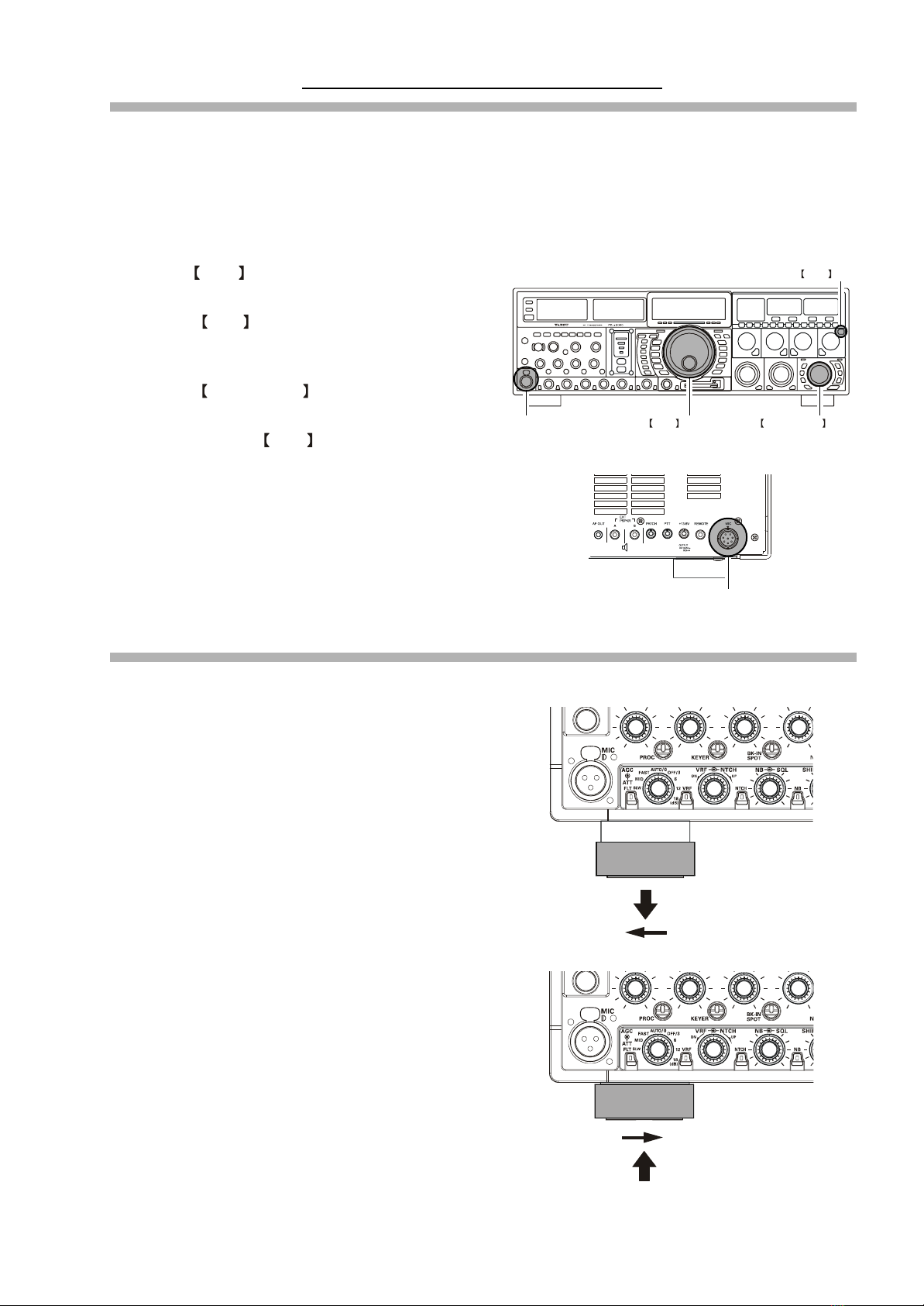
3. Connecting and Selecting the Microphone ......................... 5
4. Extending the Front Feet ..................................................... 5
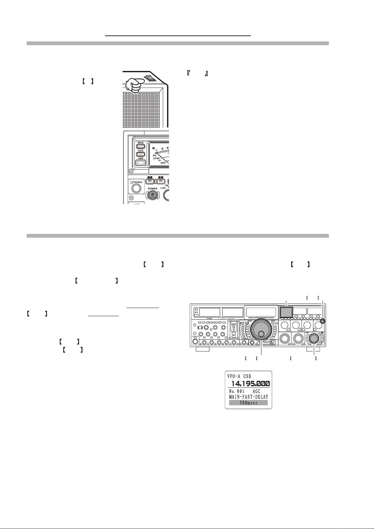
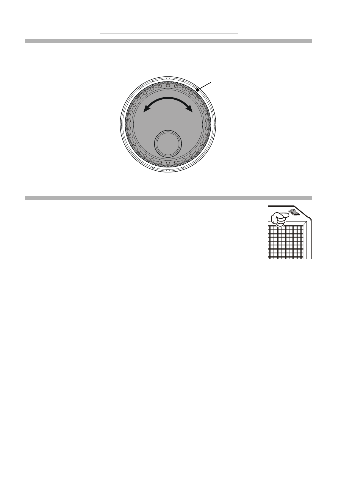
5. Adjusting the Main Dial Torque .......................................... 6
6. Restarting Power after a Voltage Fluctuation ...................... 6
7. Resetting the Microprocessor .............................................. 7
Resetting Memories (Only) ............................................... 7
Menu Resetting ................................................................. 7
Full Reset .......................................................................... 7
Features ................................................................ 8
Accessories ........................................................ 10
Options ............................................................... 11
Installation and Interconnections.....................12
Antenna Considerations ........................................................ 12
About Coaxial Cable ............................................................. 12
Grounding .............................................................................. 13
Antenna and FPS-9000H Power Supply Connections .......... 14
Connection of Microphone, Headphones,
and FH-2 Remote Control Keypad ........................................ 15
Key, Keyer, and Computer-Driven Keying Interconnections 16
Connecting a GPS Receiver .................................................. 16
VL-1000 Linear Amplifier Interconnections ......................... 17
Interfacing to Other Linear Amplifiers .................................. 18
Plug/Connector Pinout Diagrams .................... 19
Front Panel Controls ......................................... 20
Rear Panel .......................................................... 36
FPS-9000H Front Panel Controls ..................... 40
FPS-9000H Rear Panel ....................................... 41
Frequency Display ............................................. 39
FH-2 Operation ................................................... 42
Basic Operation:
Receiving on Amateur Bands ........................... 43
Operation ............................................................................... 43
Operation on 60-Meter (5 MHz) Band (U.S. version only) .. 46
CLAR (Clarifier) Operation on Main (VFO-A) .................... 47
LOCK .................................................................................... 48
DIM ....................................................................................... 48
B-DISP OFF .......................................................................... 49
Convenient Features ......................................... 50
Dual Receive ......................................................................... 50
Dual Receive: Full Duplex Operation ................................... 51
P.BACK (Audio Playback) from Main (VFO-A) Receiver ... 54
“My Bands” Operation .......................................................... 55
Band Stack Operation ............................................................ 56
C.S (Custom Switch) ............................................................. 56
Dial Swap Configuration (AF/RF GAIN controls) ............... 57
Data Management Feature ..................................................... 58
More Frequency Navigation Techniques ............................... 59
Antenna Selection .................................................................. 60
Changing the Speaker Output Configuration ........................ 61
Receiver Operation (Front End Block Diagram) ................... 62
IPO (Intercept Point Optimization) ....................................... 63
ATT ........................................................................................ 64
RF Gain (SSB/CW/AM Modes) ............................................ 65
Advanced Interference-
Suppression Features ....................................... 66
Using the VRF (Variable RF Front-end Filter) ..................... 66
Interference Rejection ....................................... 67
R.FLT (Roofing Filters) ......................................................... 67
CONT (Contour) Control Operation ..................................... 68
IF SHIFT Operation (
SSB/CW/RTTY/PKT/AM Modes
) ..................... 69
WIDTH (
IF DSP Bandwidth
) Tuning (
SSB/CW/RTTY/PKT Modes
) ......... 70
Using IF Shift and Width Together ................................. 71
IF Notch Filter Operation (
SSB/CW/RTTY/PKT/AM Modes
) ............. 72
Digital Noise Reduction (DNR) Operation ........................... 73
NARROW (NAR) One-Touch IF Filter Selection ................ 74
Digital Notch Filter (DNF) Operation ................................... 75
IF Noise Blanke (NB) Operation ........................................... 76
Tools for Comfortable and
Effective Reception .................... 77
AGC (Automatic Gain Control) ............................................ 77
SLOPED AGC Operation ............................................... 78
Mute Feature Main (VFO-A) Band ...................................... 79
Audio Limiter (AFL) Feature ................................................ 79
Adjacent Channel Monitor (ACM) (CW Mode Only) .......... 80
Audio Filter Operation .......................................................... 81

Page 3FT DX 9000MP OPERATION MANUAL
TABLE OF CONTENTS
SSB/AM Mode Transmission
(Let's Look at the Transmitter. . .)..................... 82
Phantom Voltage for Condenser Microphones ...................... 83
Using the Automatic Antenna Tuner ................ 84
ATU Operation ...................................................................... 84
About ATU Operation ............................................................ 85
Lithium Battery Replacement ................................................ 86
SSB/AM Mode Transmission ............................ 87
Using the Speech Processor (SSB, AM Mode) ..................... 87
Adjusting the SSB Transmitted Bandwidth ........................... 89
Signal Quality Enhancement Using the
Parametric Microphone Equalizer ......................................... 90
Low- Distortion CLASS-A Operation ................................... 92
Voice Memory ....................................................................... 94
Convenient Transmitter Accessories ............... 96
VOX: Automatic TX/RX Switching using Voice Control
(SSB/AM/FM Modes) ........................................................... 96
Using the MONITOR ............................................................ 96
Split Operation Using the TX Clarifier (
VFO-A Operation
) ......... 97
Clarifier Offset Bar Indicator .......................................... 97
Split-Frequency Operation .................................................... 98
Quick Split Operation ..................................................... 99
Full Duplex Operation ......................................................... 100
CW Mode Operation ........................................ 102
Setup for Straight Key (
and Straight Key emulation
) Operation ...... 101
Using the Built-in Electronic Keyer .................................... 103
Full Break-in (QSK) Operation ..................................... 103
Setting the Keyer Weight (Dot/Space:Dash ) Ratio ...... 104
Selecting the Keyer Operating Mode ............................ 104
CW Convenience Features ............................. 105
CW Spotting (Zero-Beating) ............................................... 105
Using CW Reverse .............................................................. 106
CW Delay Time Setting ....................................................... 107
CW Pitch Adjustment .......................................................... 107
Contest Memory Keyer ....................................................... 108
Message Memory .......................................................... 108
TEXT Memory .............................................................. 110
FM Mode Operation ......................................... 112
Operation ............................................................................. 112
Repeater Operation .............................................................. 113
Convenient Memory Functions ...................... 114
QMB (Quick Memory Bank) ............................ 115
QMB Channel Storage ........................................................ 115
QMB Channel Recall .......................................................... 115
Memory Groups ............................................... 116
Memory Group Assignment ................................................ 116
Choosing the Desired Memory Group ................................ 116
Memory Operation ........................................... 117
Memory Storage .................................................................. 117
Memory Channel Recall ...................................................... 117
Checking a Memory Channel’s Status .......................... 118
Erasing Memory Channel Data ........................................... 118
Moving Memory Data to the Main (VFO-A) Band ............ 119
Memory Tune Operation ............................................... 119
Operation on Alaska Emergency Frequency:
5167.5 kHz (U.S. Version Only) ....................... 120
Operation on the 60-Meter Band (
U.S. Version
) .. 121
VFO and Memory Scanning ............................122
VFO Scanning ..................................................................... 122
Memory Scan ....................................................................... 122
PMS ................................................................... 123
Packet Operation ............................................. 124
RTTY (Radio TeleType) Operation .................. 125
Miscellaneous AFSK-based Data Modes ....... 126
About the Transverter Output Terminal ......... 127
Menu Mode ....................................................... 128
Using the Menu ................................................................... 128
Menu Mode Reset ......................................................... 128
Menu Mode Setting Table ................................................... 129
Menu Mode Setting ............................................................. 133
Customized Option .......................................... 149
About Customization Options ............................................. 149
RF µ-Tuning Unit (
MTU-160, MTU-80/40, MTU-30/20
) .... 150
TFT Display Unit (
TFT-9000
) ................................ 152
Specifications ................................................... 156

Page 4 FT DX 9000MP OPERATION MANUAL
Before You Begin. . .
1. Connecting AC Power
There are two power switches on this transceiver, one each on the rear and front panels. If the rear panel’s Power switch is
not turned on, the front panel Power switch will not function.
ÌPush the Power switch on the
FPS-9000H to the I position
to apply power from the power
supply to the transceiver’s
OCXO (Reference Crystal Oven)
and to enable the front panel
power switch.
ÌPress and hold in the front panel
Power switch for two seconds to
turn the transceiver on.
Note
The self-check function of the CPU inside the radio will
begin.
If the optional RF µ-Tuning Unit is installed, the µ-Tun-
ing circuitry will receive the data from the CPU, and it
will perform its own self-check, and will preset itself to
the proper settings for the current operating frequency.
While the µ-Tuning circuitry is obtaining the data, the drive
mechanism will move from one end of its range to the
other end (fast), and this will cause a temporary “motor”
noise that can be heard; this, does not represent any trouble
or problem.
When the radio is turned on for the first time, it takes about
50 seconds (from turning the radio on to completing the
self-check) until the radio becomes ready to use; how-
ever, from the next time you turn it on, it will take around
10 seconds until the transceiver is ready for full opera-
tion.
2. Configuring Your FT DX 9000MP Using the Menu
The FT DX 9000MP is configured, at the factory, with its various functions set up in a manner typical for most operation. Via
the “Menu” system, you may change these settings to match the way you want your transceiver to operate.
Menu programming is enabled by pressing the MNU (Menu) key momentarily. You may then rotate the Main Tuning
Dial to display the desired Menu item, in the menu list, on the LCD display. Each of the settings can be changed or
customized via the CLAR/VFO-B knob, as you like, in this mode.
Once you have made a change to the configuration of a
Menu item or items, you must press and hold in the
MNU (Menu) key for two seconds to save the new set-
tings and exit to normal operation.
If you wish to cancel a change to a Menu item or items,
just press the MNU key momentarily. If you do not press
and hold in the MNU key in for two seconds, any changes
you have made will not be saved.
MNU Key
CLAR/VFO-B KnobMain Tuning Dial
Menu Item
Menu Setting
LCD Display

Page 5FT DX 9000MP OPERATION MANUAL
3. Connecting and Selecting the Microphone
The FT DX 9000MP comes equipped with two microphone connectors: the front panel includes a “Cannon” (XLR) three-
pin connector, while the rear panel provides an eight-pin (round) connector.
As shipped from the factory, the front panel XLR connector is engaged for operation, and the rear panel 8-pin microphone
jack is not connected. If you wish to enable the 8-pin connector instead of the XLR connector, use the Menu to accomplish
this. Note that you may leave microphones connected to both jacks, and may select the microphone you want for operation
on a particular operating mode (SSB, AM, FM, etc.), as well!
ÌPress the MNU (Menu) key momentarily to enter
the Menu Mode.
ÌRotate the Main Tuning Dial to select Menu Item
#069, located within the “MODE SSB” group: SSB
MIC SELECT.
ÌRotate the CLAR/VFO-B knob to change the set-
ting of Menu #069 from “FRONT” to “REAR.”
ÌPress and hold in the MNU (Menu) key for two sec-
onds to save the new setting and exit to normal opera-
tion.
ÌIn a similar manner, you may use Menu #040 (AM
MIC SEL) in the MODE-AM Menu Group to select
the microphone jack to be used during AM operation,
and Menu #059 (FM MIC SEL) in the MODE-FM
Menu Group to select the microphone to be used dur-
ing FM transmission.
4. Extending the Front Feet
In order to elevate the front panel for easy viewing, the front left and right feet of the bottom case may be extended.
ÌPull the front legs outward from the bottom panel.
ÌRotate the legs counter-clockwise to lock them in the
extended position. Be sure the legs have locked se-
curely in place, because the transceiver is quite heavy
and an unlocked leg could result in damage, should
the transceiver move suddenly.
Before You Begin. . .
“FRONT”
Cannon (XLR)
3-pin connector
“REAR”
8-pin microphone jack
Retracting the Front Feet
ÌRotate the legs clockwise, and push them inward while
rotating to the right.
ÌThe front feel should now be locked in the retracted
position.
EXTEND
RETRACT
MNU Key
CLAR/VFO-B KnobMain Tuning Dial

Page 6 FT DX 9000MP OPERATION MANUAL
5. Adjusting the Main Dial Torque
The torque (drag) of the Main Tuning Dial may be adjusted according to your preferences. Simply hold down the rear skirt
of the knob, and while holding it in place rotate the Main Dial itself to the right to reduce the drag, or to the left to increase
the drag.
Before You Begin. . .
6. Restarting Power after a Voltage Fluctuation
If your AC mains power should suffer a significant fluctuation or interruption, we recommend that
you go through a complete power-up cycle, in order to ensure that all circuits are properly initialized.
To do this, be sure the front panel Power switch is turned off, then set the FPS-9000H’s Power switch
to the “O” position. Now unplug the AC cable from the rear panel of the FPS-9000H, and wait ten
seconds. Plug the AC cable back in, set the FPS-9000H’s Power switch to “O,” and now press and
hold in the front-panel Power switch for two seconds to turn the transceiver on. After about 50 sec-
onds, all circuits wil be initialized, and normal operation may resume.
TIGHTEN TOOSEN
HOLD THE SKIRT

Page 7FT DX 9000MP OPERATION MANUAL
Before You Begin. . .
7. Resetting the Microprocessor
ËResetting Memories (Only)
Use this procedure to reset (clear out) the Memory channels previously stored, without affecting any configuration changes
you may have made to the Menu settings.
1. Press the front panel’s POWER switch to turn the
transceiver off.
2. Press and hold in the A M switch; while holding
it in, press and hold in the front panel’s POWER
switch to turn the transceiver on. Once the transceiver
comes on, you may release the A M switch.
ËMenu Resetting
Use this procedure to restore the Menu settings to their factory defaults, without affecting the memories you have pro-
grammed.
1. Press the front panel’s POWER switch to turn the
transceiver off.
2. Press and hold in the MNU (Menu) key; while hold-
ing it in, press and hold in the front panel’s POWER
switch to turn the transceiver on. Once the transceiver
comes on, you may release the MNU (Menu) key.
ËFull Reset
Use this procedure to restore all Menu and Memory settings to their original factory defaults. All Memories will be cleared
out by this procedure.
1. Press the front panel’s POWER switch to turn the
transceiver off.
2. Press and hold in the FAST and LOCK switches;
while holding them in, press and hold in the front
panel’s POWER switch to turn the transceiver on.
Once the transceiver comes on, you may release the
other two switches. FAST Switch
&
LOCK Switch
POWER Switch
A M SwitchPOWER Switch
MMU KeyPOWER Switch

Page 8 FT DX 9000MP OPERATION MANUAL
FEATURES
Superior Visibility and Logical, Fatigue-reducing Panel Layout
The front panel layout is logically crafted, with the large-aperture main frequency display squarely in the middle of the front panel; the
two large S-meters to the left providing instant recognition of signal strength.
Just as in an aircraft cockpit, the panel meters and the LCD display are canted slightly toward the center for maximum visibility.
Large, Multi-colored VFD Fluorescent Display
A proprietary, high-brightness VFD (fluorescent) display is incorporated in the FT DX 9000MP, providing outstanding visibility and easy
reading of the important frequency information, whether in dim or bright lighting environments.
Function-Indicating LEDs
The many function status indications on the front panel are clearly identified by the operator, thanks to the innovative multi-color LEDs
incorporated in design. A Red LED indicates that a function is engaged on the Main Band, while an Orange LED shows that the function
is engaged on the Sub Band.
Indirect Illumination
For ease of nighttime operation, the controls on the front panel are indirectly illuminated, thanks to carefully-positioned lamps in the
frame underneath the meters and the Band switch.
Aluminum-Die-Cast Oversized Main Tuning Dial
The Main Tuning Dial is a large-diameter (3.2”/81 mm) dial directly coupled to the magnetic rotary encoder which drives the HRDDS
via microprocessor control. Its heavy weight (7 oz./200 g) and quality mounting and construction provide a smooth “flywheel” effect
during operation, ideal for quick cruising up and down a band.
Oversized Knobs for Most Important Functions
The concentric AF/RF Gain, SHIFT/WIDTH, and CLAR/VFO-B knobs are conveniently located at the right-bottom side of the Front
Panel, for ease of access to these important controls.
World’s First 400 MHz HRDDS Local Oscillator
So as to optimize spurious-free dynamic range in a multi-signal environment, Yaesu’s engineers have introduced the world’s first
HRDDS (High Resolution Direct Digital Synthesizer) as the first local oscillator of the FT DX 9000MP. Dividing directly from this high
frequency, this local oscillator design ensures extraordinarily low noise, resulting in improved weak-signal reception even on a crowded
band during a weekend contest.
New-design Large-area OCXO Reference Oscillator
Serving as the master reference oscillator for the transceiver, the 10 MHz OCXO (Oven Controlled Crystal Oscillator) is a large-area (50
x 50 mm/2” x 2”) oven-stabilized oscillator operating at high temperature, for industry-leading frequency stability rated at 0.03 ppm
over the temperature range –10° to +60° C (–14° to +140° F).
Triple-conversion Design with Optimized Gain Distribution
Taking into account the most efficient transceiver design concept consistent with high performance we have adopted a triple-conversion
IF structure, utilizing a first IF at 40 MHz, a second IF at 455 kHz, and the third IF at 30 kHz (for FM, the 3rd IF is at 24 kHz). Gain
distribution through all stages is carefully optimized, for preservation of high system dynamic range.
Ultra-strong Receiver Front End
YAESU’s outstanding RF-stage filtering establishes a clean performance that allows the rest of the receiver to perform at a high level. By
reducing the ingress of energy from very strong sources like Shortwave Broadcast, local AM/FM/TV stations, and other signal sources,
the overall purity of the spectrum delivered to the RF Amplifier first mixer, and subsequent stages is maintained, and the system
Blocking Dynamic Range is also enhanced.
Compact Flash (CF) Card for Data Management
A Compact Flash card is supplied with every FT DX 9000MP, for preservation of transceiver configuration settings along with Log Book
archival data.
Professional-Grade Cannon (XLR) Microphone Connector
The FT DX 9000MP incorporates, for the first time ever in an Amateur Radio transceiver, a balanced-input “Cannon” (XLR) microphone
connector on the front panel, for use with studio-grade professional microphones. A round 8-pin microphone jack is also provided on the
rear panel.
Two High-precision Analog Meters (Page 27)
The FT DX 9000MP incorporates two large (3.4”/86 mm) high-precision analog meters, for the utmost accuracy in measuring transceiver
performance. Visibility is enhanced by the oversized meter scales, making the meters easy to read at all times.
Separated Clarifier Display (Pages 47, 97)
A clearly-separated display window within the main frequency display area contains receiver and/or transmitter frequency offset (“Clari-
fier”) data, for quick comprehension by the operator.
YAESU Custom-designed 32-Bit Floating Point IF DSP (Page 62)
The new IF DSP system, utilizing a TI TMS320C6711 device, is a high-speed 32-bit floating point circuit designed with a unique
objective: to do away with the “digital” sound of many DSP filtering systems, and emulate the “Analog Sound” so familiar and comfort-
able to HF DX and Contest operators. The result is a leading-edge receiver that has the “feel” of a traditional analog receiver, but with
the flexibility and superb filtering capability of a modern digital filtering system.

Page 9FT DX 9000MP OPERATION MANUAL
FEATURES
VRF (Variable RF Filter) Preselector Filter (Page 66)
Yaesu’s robust VRF (Variable RF Filter) preselector provides a relay-selected RF selectivity much tighter than that afforded by tradi-
tional bandpass filter networks. Sealed relays select heavy-duty inductors and capacitors, providing a tracking RF filter that protects the
RF amplifier and following stages from strong out-of-band energy.
First IF 3 kHz Roofing Filter (Page 24, 67)
In the 40 MHz 1st IF, three selectable roofing filters are provided, in bandwidths of 3 kHz, 6 kHz, and 15 kHz, to protect the following
stages from strong signals that could degrade dynamic range in the first IF amplifier and subsequent stages. The roofing filters are
automatically assigned according to the operating mode, but the operator may override the automatic selections on the fly.
CONTOUR Filter Enhances “Analog Feeling” of DSP Filters (Page 29, 68)
The DSP-based Contour system is a unique five-band filter that may be used to roll off or peak the IF response. It is chiefly useful for
modifying the response of the ultra-sharp DSP filters, allowing you to roll off (or emphasize) certain frequency components. Oftentimes,
the result is that a difficult-to-understand signal suddenly will pop out of the background noise as solid copy.
SLOPED AGC Circuitry (Page 78)
In traditional AGC systems, all signals rising above a certain RF level are then clamped together at the same audio output, so as to
prevent distortion throughout the IF and AF stages. In the FT DX 9000MP, however, you can engage the “Sloped” AGC capability to
provide an AGC response whereby ever-increasing signal strength results in a slightly-louder audio response, still without accompany-
ing distortion. This lets you use your brain to sort out weak signals from strong ones more effectively.
Receiver AF Limiter Circuit (Page 32, 79)
Occasionally a noise burst or a sudden transmission from a loud station may startle you if you have the AF Gain turned up, and may even
damage your hearing temporarily. The FT DX 9000MP provides an AF Limiter (AFL) circuit which, once engaged, clamps an upper limit
on the available audio output power, much like the AGC circuit does in the RF and IF stages.
“Adjacent Channel Encroachment” S-Meter Monitor (Page 33, 80)
When operating CW in a narrow bandwidth like 300 Hz, you may not be aware of the presense of strong stations that may be making it
difficult for others to hear you. In these situations, the “ACM” (Adjacent Channel Monitor) will take over the Sub Receiver, center it on
the Main Receiver frequency, and display ± 1.2 kHz of signal activity on the Sub Receiver’s S-meter (without feeding the interfering
audio through). This alerts you to the situation, and you can QSY or ask the other station to QSY.
Rugged, High-Output Final Amplifier Design (Page 93)
The final amplifier stage of the FT DX 9000MP utilizes parallel push-pull SD2931 MOS FET devices in a conservative, high-stability
design. The large-area die-cast aluminum heat sink is monitored thermostatically, and a quiet cooling fan will engage when the heat sink
temperature rises during long periods of high-power transmission.
Ultra-linear Class-A Operation Capability (Page 92)
The FT DX 9000MP’s Class-A capability provides ultra-linear amplifier operation at 100 Watts of power output. Typically, 3rd-order
IMD products are suppressed more than 50 dB, while 5th- and higher-order distortion products are at least 70 dB down during Class-A
operation.
Parametric Microphone Equalizer Circuit (Page 90)
For unmatched flexibility in tailoring your microphone’s audio to match your voice, Yaesu’s engineers have incorporated the industry’s
first Three-Band Parametric Microphone Equalizer, which allows you to enhance or suppress frequency components in three different
audio bands. Equalization may be applied independently to microphones attached to the front and rear panel microphone jacks.
Connecting Your After-market Computer Monitor for Multiple Function Displays
(Refer to the separate Data Management Unit Operating Manual)
Connection of your after-market computer monitor (not supplied) allows display of a number of important and useful operating status
and function displays. These include the Menu mode, World Clock, Spectrum Scope, Audio Scope and Oscilloscope, Logbook, Tem-
perature/SWR monitoring, Rotator Control, and Memory Channel listings.
Customization of Your FT DX 9000MP
A wide range of custom configuration options (other than a better location or taller tower!) are available for your FT DX 9000MP,
allowing you to build a Dream Station from the “MP” version foundation.
Because these options involve high-technology modules, please consult WDXC regarding factory installation of these items.
ÌRF µ-Tuning Units (MTU-160, MTU-80/40, MTU-30/20)
On the 14 MHz and lower bands, the µ-Tuning Units provide extraordinarily high Q; the resulting steep shape factor is a powerful
aid for reducing off-frequency interference. Separate modules are available for the 1.8 MHz, 3.5/7 MHz, and 10.1/14 MHz bands,
and they may be installed on the Main Receiver only (not in the Sub Receiver).
Thanks to the large (1.1”/28 mm) inductor through which a stack of ferrite cores is adjusted, the narrow RF bandwidth of the µ-
Tuning System provides unmatched protection for the receiver front end and following circuits.
ÌTFT Display Unit (TFT-9000)
The TFT-9000 TFT Display Unit allows to display the enable the “World Clock,” “Spectrum Scope,” “Audio Scope/Oscilloscope,”
“Logbook,” “Rotator Control,” and “Temperature/SWR Status Display” functions to the internal 6.5” TFT Display, which provides 800
x 480 dot screen high resolution and easy viewing.

Page 10 FT DX 9000MP OPERATION MANUAL
ACCESSORIES
SUPPLIED ACCESSORIES
Plug Details and Part Numbers
FH-2
Remote Control Keypad
CF Card
(64 MB: Q9000838)
AC Power Cord1
Microphone Extend Cable
(8 Pin
Modular)
2
Piugs
RCA Plug (P0091365)
6 pcs
Items are shown for illustrative purposes only, and may vary slightly in appearance.
1: AC Power Cord
USA: T9017882
Europe: T9013285
Australia: T9013283A
UK: T9013285
2: This microphone cable is for use with the optional
MD-200A8X, MD-100A8X, or MH-31B8 micro-
phones.
3.5 mm 2-contact Plug
(P0090034)
2 pcs
3.5 mm 3-contact Plug
(P0091046)
1 pc
1/4-inch 3-contact Plug
(P0090008)
2 pcs
4-pin DIN Plug (P0091004) 1 pc
5-pin DIN Plug (P0091006) 1 pc
7-pin DIN Plug (P0091419) 1 pc
8-pin DIN Plug (P0090651) 1 pc
HOperating Manual
HWarranty Card
FPS-9000H
External Power Supply
with Dual Speakers and
Audio Filters

Page 11FT DX 9000MP OPERATION MANUAL
OPTIONS
Lightweight Stereo Headhones
YH-77STA
Linear Amplifier / AC Power Supply
VL-1000 / VP-1000
Ultra-High-Fidelity Desk-Top Microphone
MD-200A8X
Desk-Top Microphone
MD-100A8X
AVAILABLE OPTIONS
MD-200A8X
Customization Options
RF µ-Tuning Unit A MTU-160 (160 m Band)
RF µ-Tuning Unit B MTU-80/40 (80/40 m Bands)
RF µ-Tuning Unit C MTU-30/20 (30/20 m Bands)
TFT Display Unit TFT-9000

Page 12 FT DX 9000MP OPERATION MANUAL
INSTALLATION AND INTERCONNECTIONS
ANTENNA CONSIDERATIONS
The FT DX 9000MP is designed for use with any antenna system providing a 50 Ohm resistive impedance at the desired
operating frequency. While minor excursions from the 50-Ohm specification are of no consequence, the transceiver’s
Automatic Antenna Tuner may not be able to reduce the impedance mismatch to an acceptable value if the Standing Wave
Ratio (SWR) present at the Antenna jack is greater than 3:1.
Every effort should, therefore, be made to ensure that the impedance of the antenna system utilized with the FT DX 9000MP
be as close as possible to the specified 50-Ohm value.
Any antenna to be used with the FT DX 9000MP must, ultimately, be fed with 50 Ohm coaxial cable. Therefore, when using
a “balanced” antenna such as a dipole, remember that a balun or other matching/balancing device must be used so as to
ensure proper antenna performance.
The same precautions apply to any additional (receive-only) antennas connected to the RX ANT jack; if your receive-only
antennas do not have an impedance near 50 Ohms at the operating frequency, you may need to install an external antenna
tuner to obtain optimum performance.
ABOUT COAXIAL CABLE
Use high-quality 50-Ohm coaxial cable for the lead-in to your FT DX 9000MP transceiver. All efforts at providing an
efficient antenna system will be wasted if poor quality, lossy coaxial cable is used. This transceiver utilizes standard “M”
(“PL-259”) type connectors, except for the “RX OUT” BNC connectors used for special filters, etc.
TYPICAL PL-259 INSTALLATION
1/16"
3/4"
1 1/ 8"
3/4''
1/8''
5/8''3/8''
Adapter

Page 13FT DX 9000MP OPERATION MANUAL
INSTALLATION AND INTERCONNECTIONS
GROUNDING
The FT DX 9000MP HF transceiver, like any other HF communications apparatus, requires an effective ground system for
maximum electrical safety and best communications effectiveness. A good ground system can contribute to station effi-
ciency in a number of ways:
ÌIt can minimize the possibility of electrical shock to the operator.
ÌIt can minimize RF currents flowing on the shield of the coaxial cable and the chassis of the transceiver; such currents
may lead to radiation which can cause interference to home entertainment devices or laboratory test equipment.
ÌIt can minimize the possibility of erratic transceiver/accessory operation caused by RF feedback and/or improper cur-
rent flow through logic devices.
An effective earth ground system make take several forms; for a more complete discussion, see an appropriate RF engineer-
ing text. The information below is intended only as a guideline.
Typically, the ground connection consists of one or more copper-clad steel rods, driven into the ground. If multiple ground
rods are used, they should be positioned in a “V” configuration, and bonded together at the apex of the “V” which is nearest
the station location. Use a heavy, braided cable (such as the discarded shield from type RG-213 coaxial cable) and strong
cable clamps to secure the braided cable(s) to the ground rods. Be sure to weatherproof the connections to ensure many
years of reliable service. Use the same type of heavy, braided cable for the connections to the station ground bus (described
below).
Inside the station, a common ground bus consisting of a copper pipe of at least 25 mm (1”) diameter should be used. An
alternative station ground bus may consist of a wide copper plate (single-sided circuit board material is ideal) secured to the
bottom of the operating desk. Grounding connections from individual devices such as transceivers, power supplies, and
data communications devices (TNCs, etc.) should be made directly to the ground bus using a heavy, braided cable.
Do not make ground connections from one electrical device to another, and thence to the ground bus. This so-called “Daisy-
Chain” grounding technique may nullify any attempt at effective radio frequency grounding. See the drawing below for
examples of proper grounding techniques.
Inspect the ground system - inside the station as well as outside - on a regular basis so as to ensure maximum performance
and safety.
Besides following the above guidelines carefully, note that household or industrial gas lines must never be used in an
attempt to establish an electrical ground. Cold water pipes may, in some instances, help in the grounding effort, but gas lines
represent a significant explosion hazard, and must never be used.

Page 14 FT DX 9000MP OPERATION MANUAL
ANTENNA AND FPS-9000H POWER SUPPLY CONNECTIONS
Please refer to the illustration for guidelines regarding connection of your antenna(s) and the FPS-9000H Power Supply.
Advice
GDo not position this apparatus in a location with direct
exposure to sunshine.
GDo not position this apparatus in a location exposed to
dust and/or high humidity.
GEnsure adequate ventilation around this apparatus, so
as to prevent heat build-up and possible reduction of
performance due to high heat.
GDo not install this apparatus in a mechanically-unstable
location, or where objects may fall onto this product
from above.
GTo minimize the possibility of interference to home
entertainment devices, take all precautionary steps in-
cluding separation of TV/FM antennas from Amateur
transmitting antennas to the greatest extent possible,
and keep transmitting coaxial cables separated from
cables connected to home entertainment devices.
INSTALLATION AND INTERCONNECTIONS
Use a short, thick, braided
cable to connect your sta-
tion equipment to the bur-
ied ground rod (or alterna-
tive earth ground system).
Ground Rod
ANTENNA "1"
ANTENNA "2"
ANTENNA "3"
ANTEN
N
A
"
4
"
E
X
T
B
A
I
N
P
U
T
スピーカーケーブル ( の
FPS-9000 )
付属品
B INPUT
EXT A
スピーカーケーブル ( の
-9000 )FPS
付属品
FT DX 9000MP FPS-9000H
Connect to the AC line outlet
AC 100 V - AC 240 V
Connect the OUTPUT Plug from
the FPS-9000H to the DC IN Jack
of the FT DX 9000MP
Speaker Cable (Supplied with the FPS-9000H)
GEnsure that the AC power cord is not subject to undue
stress or bending, which could damage the cable or
cause it to be accidentally unplugged from the rear panel
AC input jack.
GBe absolutely certain to install your transmitting
antenna(s) such that they cannot possibly come in con-
tact with TV/FM radio or other antennas, nor with out-
side power or telephone lines.
Note
Please be sure that both the transceiver’s front panel
POWER switch and the FPS-9000H’s main power
switch are both turned off any time you plug in or unplug
any power cable to/from the FPS-9000H. This will avoid
the possibility of potentially-damaging spikes and/or elec-
trical shock.

Page 15FT DX 9000MP OPERATION MANUAL
C
ONNECTION
OF
M
ICROPHONE
, H
EADPHONES
,
AND
FH-2 R
EMOTE
C
ONTROL
K
EYPAD
This transceiver was shipped from the factory in configuration for a microphone input via the Front Panel XLR
connector. To use the Rear Panel microphone with an 8-pin round connector, please change the microphone set up
via the Menu.
1. To do this, first press the MNU key.
2. The Menu list will appear on the LCD display screen.
3. Rotate the Main tuning dial (VFO-A) to select menu item [MODE-SSB 069 SSB MIC SELECT].
4. Now rotate the CLAR/VFO-B knob to change the setting to Rear.
The available selections are FRONT-REAR-DATA-PC.
5. To save the set-up, press and hold in the MNU key for 2 seconds.
If the MNU key is not held for 2 seconds, the set-up will not be saved.
Note : To use the AM or FM mode, please select Menu items 040 for AM and 059 for FM, and follow the same
procedure above.
INSTALLATION AND INTERCONNECTIONS
1/4-inch 3-contact jack
Stereo Headphones
XLR connector Type Microhone
LOCK
OFFON
MIC
⑧
①
UP
②
+5V
③
DOWN
④
FA ST
⑤
GND
⑥
PTT
⑦
MIC GND
①
MIC-GND
③
MIC-Cold
②
MIC-Hot
FH-2 Remote Control Keypad 8-pin Connector Type Microphone
External After-market Monitor
Note: If you plan to leave your trans-
ceiver and external monitor turned
on for repeated, extended lengths
of time, we recommend that you
consider the use of a TFT monitor,
which does not develop a “memory”
of a particular display.

Page 16 FT DX 9000MP OPERATION MANUAL
INSTALLATION AND INTERCONNECTIONS
COMMON
COMMON
DOT
DOT
DASH
DASH
KEY, KEYER, AND COMPUTER-DRIVEN KEYING INTERCONNECTIONS
The FT DX 9000MP includes a host of features for the CW operator, the functions of which will be detailed in the “Opera-
tion” section later. Besides the built-in Electronic Keyer, two key jacks are provided, one each on the front and rear panels,
for convenient connection to keying devices.
The Menu system allows you to configure the front ane rear panel KEY jacks according to the device you wish to connect.
For example, you may connect your keyer paddle to the front panel KEY jack, and use Menu #41 for paddle input, while
connecting the rear panel’s KEY jack to the keying line from your personal computer (which emulates a “straight key” for
connection purposes), and configure the rear panel jack using Menu #43.
Both KEY jacks on the FT DX 9000MP utilize “Positive” keying voltage. Key-up voltage is approximately +5V DC, and
key-down current is approximately 1 mA.
Advice
When connecting a key or other device to the KEY jacks, use only a 3-pin (“stereo”) 1/4” phone plug; a 2-pin plug will
place a short between the ring and (grounded) shaft of the plug, resulting in a constant “key-down” condition in some
circumstances.
Pin 2
GPS DATA IN
Pin 5
GND
CONNECTING AGPS RECEIVER
If you connect a properly-equipped after-market GPS re-
ceiver (not supplied) to the COM port on the back of the
transceiver, the “Rotator” page on the External display will
automatically include a Great Circle map centered on your
location.
Connect a GPS receiver capable of output of NMEA-0183
data to the COM port. The data line connects to Pin 2, and
the ground shield connects to Pin 5.
This transceiver can support the GGA, GLL, and RMC Data
Sentences from the GPS unit.

Page 17FT DX 9000MP OPERATION MANUAL
ANT 1
ANT 2
ANT 3
ANT 4
REMOTE
ON
OFF
BAND DATA 1
BAND DATA 2
GND
ALC 2
ALC 1
PTT 2
PTT 1
INPUT 1
INPUT 2
CONTROL
DC48V IN
A
N
T
1
A
N
T
1
H
F
V
e
r
t
i
c
a
l
A
n
t
e
n
n
a
H
F
D
i
p
o
l
e
A
n
t
e
n
n
a
H
F
B
e
a
m
A
n
t
e
n
n
a
5
0
M
H
z
A
n
t
e
n
n
a
A
N
T
2
A
N
T
3
A
N
T
2
I
N
P
U
T
1
E
X
T
A
L
C
B
A
N
D
D
A
T
A
1
B
A
N
D
D
A
T
A
2
B
A
N
D
-
D
A
T
A
1
B
A
N
D
-
D
A
T
A
2
G
N
D
G
N
D
D
C
4
8
V
I
N
C
O
N
T
R
O
L
A
L
C
1
ALC CABLE (Supplied w/VL-1000)
BAND DATA CABLE (Supplied w/VL-1000)
ANTENNA CABLE (Supplied w/VL-1000)
CONTROL CABLE (User constructed)
VP-1000
VP-1000
~
D
C
I
N
FPS-9000H
INSTALLATION AND INTERCONNECTIONS
VL-1000 LINEAR AMPLIFIER INTERCONNECTIONS
Be sure that both the FT DX 9000MP and VL-1000 are turned off, then follow the installation recommendations contained
in the illustration.
On the rear panel of the VL-1000, please set the “ATT” switch to the “ON” position, and set the maximum RF
output power level to “200 W” via menu item [TX GNRL 154 TX MAX POWER]. The 400-Watt power output from
the FT DX 9000MP is far in excess of what is required to drive the VL-1000 to its full rated output.
Note
GPlease refer to the VL-1000 Operating Manual for details regarding amplifier operation.
GPlease do not attempt to connect or disconnect coaxial cables when your hands are wet.
About the CONTROL Cable
The VL-1000 may be operated with the FT DX
9000MP whether or not the CONTROL Cable is con-
nected; however, the CONTROL Cable allows you
to tune up the amplifier automatically by just press-
ing the [F SET] or [TUNE] key on the VL-1000, so
as to transmit a carrier for tuning purposes.
To link the FT DX 9000MP and VL-1000 Power
switches, set the VL-1000 REMOTE switch to the
ON position.
Control Cable Modification
Please cut off the RCA connector on one end of the
CONTROL Cable supplied with the VL-1000, and
install a 7-pin DIN connector in its place, accord-
ing to the illustration.
Pin 7
TRQ
Pin 3
GND
Pin 9
F SET COMMON
Pin 11
F SET 2

Page 18 FT DX 9000MP OPERATION MANUAL
INTERFACING TO OTHER LINEAR AMPLIFIERS
Note
GThe TX/RX switching in the linear amplifier is controlled by switching components in the transceiver. The relay circuit
of the FT DX 9000MP used for this switching is capable of switching AC voltage of 100 Volts at up to 300 mA, or DC
voltages or 60 V at 200 mA or 30 V at up to 1 Amp. In order to engage the switching relay, use Menu [TX GNRL 156
EXT AMP TX-GND] within the “TX GNRL” Menu Group; set this Menu selection to “ENABLE” to activate the
amplifier switching relay.
GThe specified range for ALC voltage to be used with the FT DX 9000MP is 0 to –4 Volts DC.
GAmplifier systems utilizing different voltages will not work correctly with the FT DX 9000MP, and their ALC lines must
not be connected if this is the case.
INSTALLATION AND INTERCONNECTIONS
E
E
RY
ALC
ACFUSEGND
RF IN
RF OUT
ANT 1
HF Antenna
INPUT 1
EXT ALC
TX GND
GND
ANT 1
50 MHz Antenna
ANT 2
GND
~DC IN
FPS-9000H
Other manuals for FTDX-9000MP
2
Table of contents
Other Yaesu Transceiver manuals

Yaesu
Yaesu FT-80C - SERVICE User manual

Yaesu
Yaesu FT-920 User manual

Yaesu
Yaesu FT-107M Manual

Yaesu
Yaesu FT-80C - SERVICE User manual

Yaesu
Yaesu VX-60R User manual

Yaesu
Yaesu FT1DR Manual

Yaesu
Yaesu FTM-350R - SOFTWARE UPDATE PROCEDURE 7110 Manual

Yaesu
Yaesu FT-690RII User manual

Yaesu
Yaesu FV-901DM User manual

Yaesu
Yaesu FT-7800R User manual