English
E
E
E
EN
E
Francais
E
a
T
a
ES
Deutsch
`
`,
E
E
ES
E
E
ŞvenSka
a.
E
E
SS
E
Es]
Italiano.......................
E
E
SS
e
SS
7
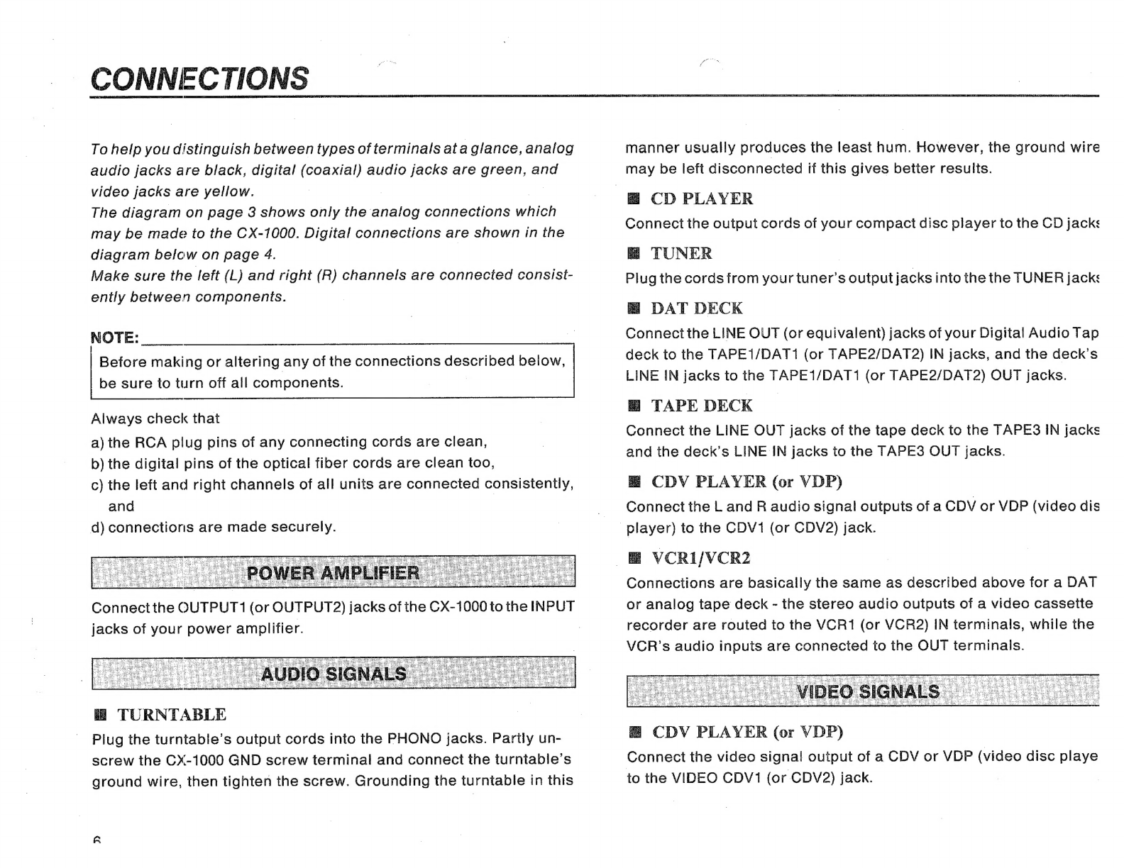
Connection
Diegram.
3
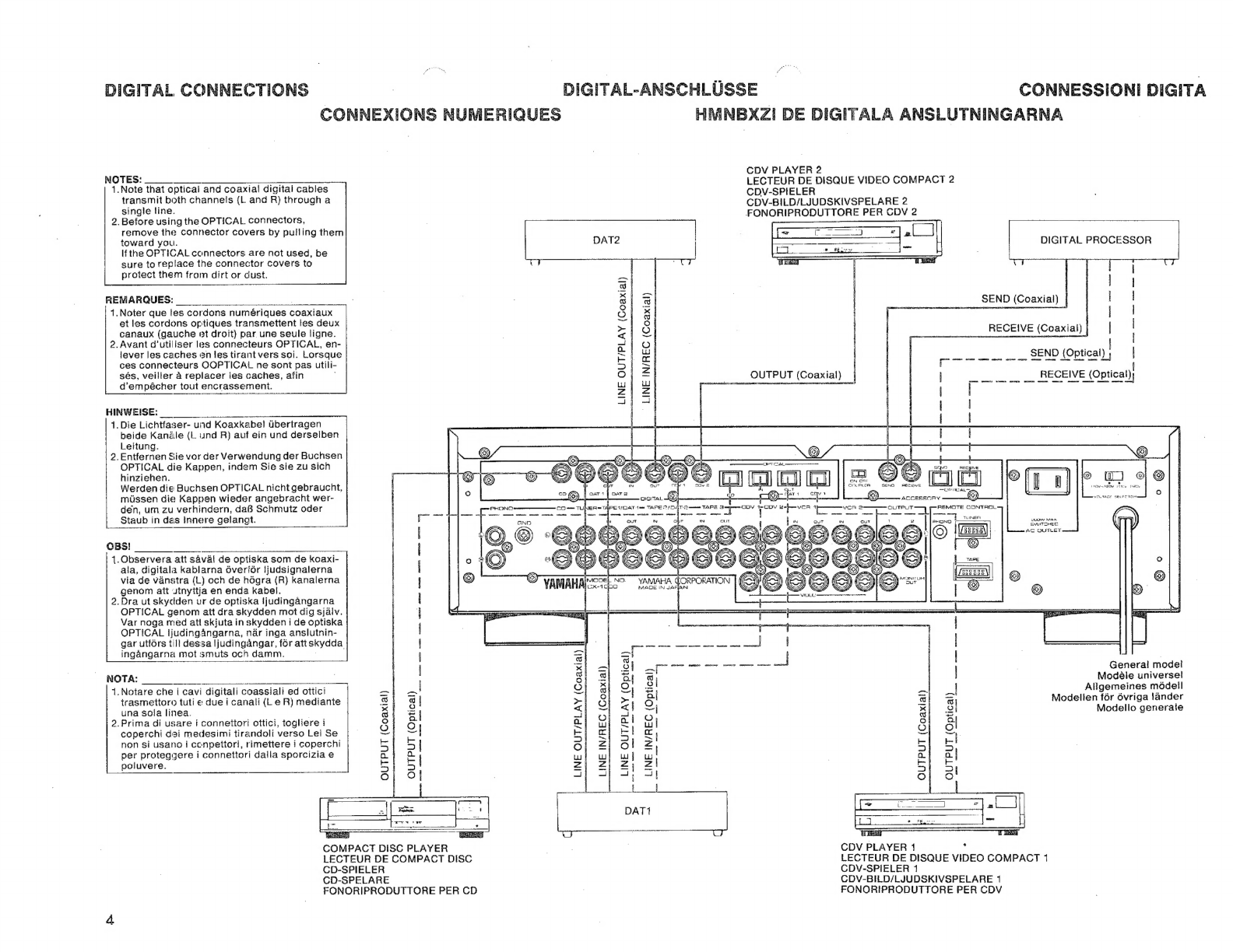
Digital
Connections
AA
4
Tone
Control
Characteristics
ANERER
85
Front
Panel
(iusiratton...
86
ele
Ee
e
odia
dan
87
tdo
ice
78
SCHEMA
des
CONNEXIONS
c.ococconcccccccnonononacnconononnonconconnoros:
3
CONNEXIOUS
Numeriques
.0..
0.
ccc
ee
eecceccnscaccarccusscecnecsesssene
4
Caracteristiques
de
Controle
de
Tonalite
.....ocooo.o.o.......
85
Illustration
du
Panneau
Avant...
86
Schéma
dè
Principe
ii
87
EEN
34
ANSCHÍUBSCHOMA
......0ccccecncnesncccarsecsscctuancseccsressceneecesesnens
3
Digital-Arschlusse
...............
Ee
4
Regelbereich
der
Klangregler
....ccccccsccscccsccnsccccecsccceneness
85
Abbildung
der
Vorderseite,
cc
ccccccccceccecceccesecsececancsecees
86
Blockschaltbild
EE
87
EEN
53
bopplingsdiagrammet.
3
Hmn
Bxzi
de
Digitala
Anslutningarna
ee
4
Klangfarfskara
Kteristik
.......cccccccccccuccsccesceecctcessevecsccnecses
85
Mlustrationen
på
Framsidan
......cccccecescccecccucsuceenecececcesess
86
BOCK
SCIANIING
EE
87
A
EA
E
T
AEE
A
70
Schema
di
Collegamento
wu...
ccccccccccecescecnccccccececeecscncaeness
3
Connessioni
Digital...
ee
get
4
Caractteristiche
di
Controllo
font.
85
Illustrazione
del
Pannello
Anteriore
o.s
86
Diagramma
di
tiusso,,
carac
nn
nrancanononon
87
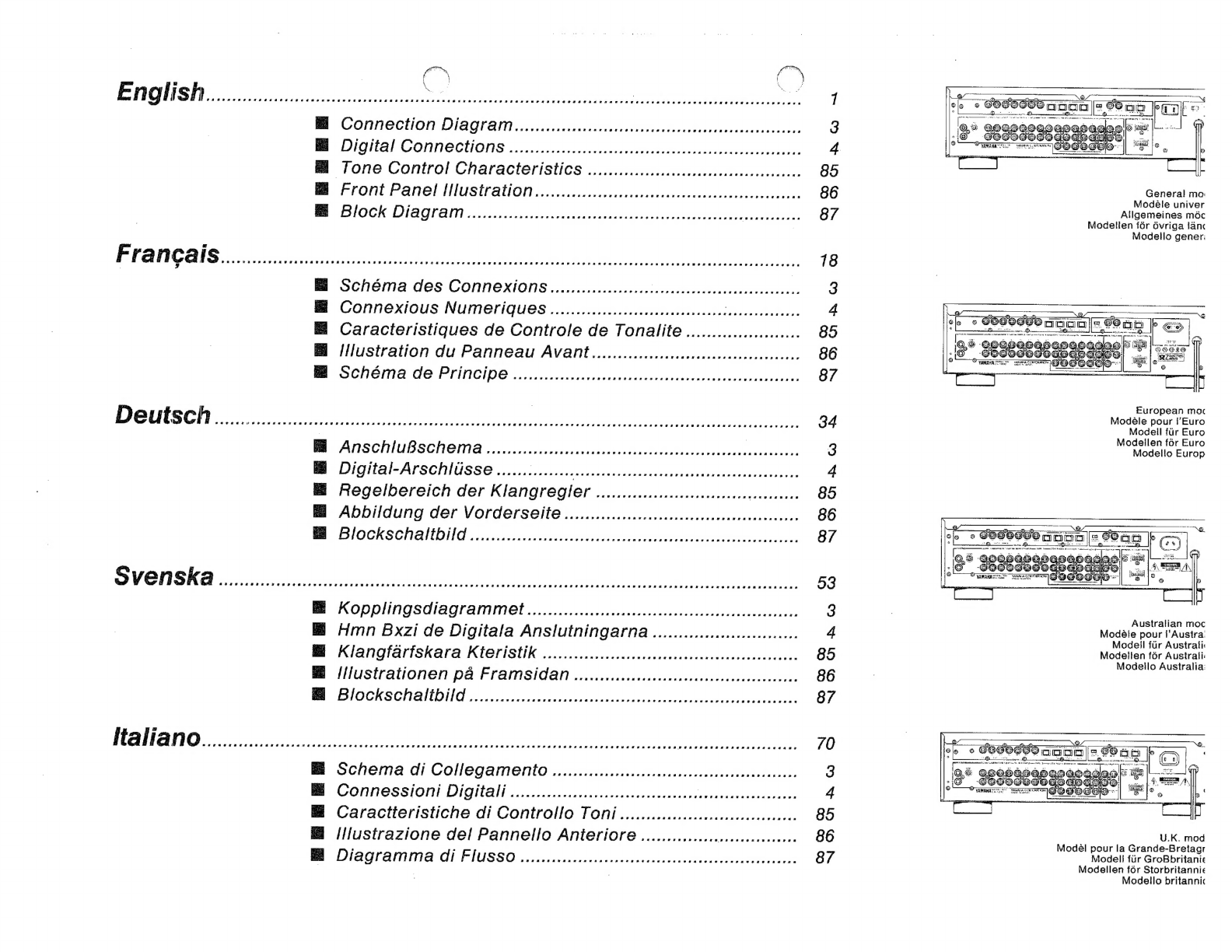
General
ma:
Modèle
univer
Allgemeines
méc
Modelen
för
övriga
lán<
Modello
gener:
European
mac
Modèle
pour
f’Euro
Modell
túr
Euro
Modellen
fór
Euro
Modelio
Europ
Australian
moc
Modele
pour
l'Austra:
Modell
für
Australi
Modellen
för
Australi:
Modello
Australia:
¿0
Soe
Y
WIER
B
e
SC
U.K.
mod
Modèl
pour
la
Grande-Bretagr
Modell
fur
GroBbritanie
Modellen
för
Storbritannie
Modello
britannic