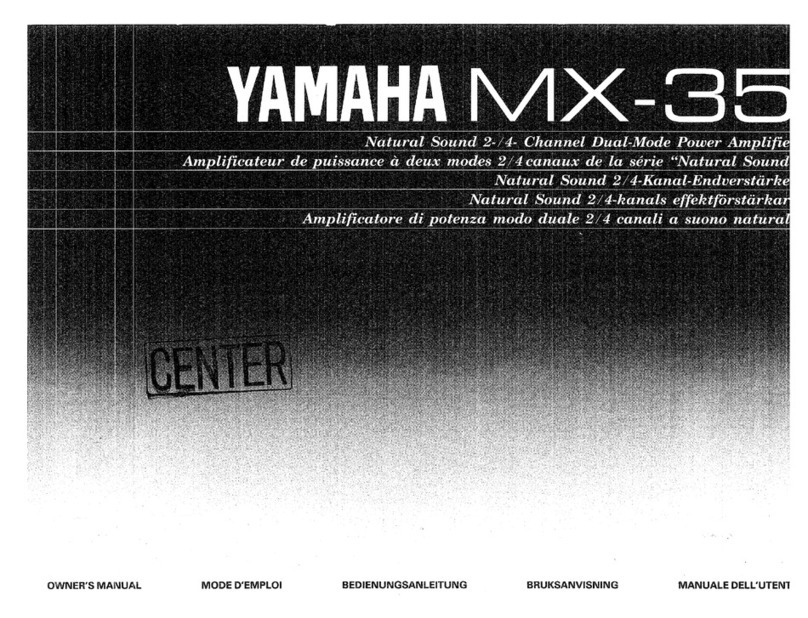
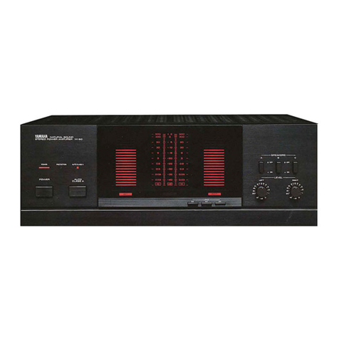
Yamaha MX-55 User manual

ae
gation
Am
pl
ZOA
Cha
2
Wipe
|
Sou
annel)
fy
aya
weaker
L
va
_Adju
UFC
ae
s
erence
IS
UN
,
MG
asec
sive
REELE
;
A
A
EAr
ArI
7
Pee
Soa
eats
EER,
la
The
ser
K
Pe
ee
a
eee
rea
rk
Be
eee
ee
a
a
ee
eo
fea!
F
ARANO
a
fi
ATAA
AT
een
ae
en
nea
aed
eer
e
ee
ee
ers
yee
ae
eevee
ene
eee
nev
eee
nese
eee
eee
er
eee
ee
re
eee
ee
eee
we
ee
rere
ORE
ee
IONS
+
Connect
panel
of
th
fe
place
for
future
ref
und-on
the
rear
|
number
can
be
fo
is
Owner's
Manual
in
a
sa
eep
th
Back
cover
Bede
recat
en
ete
eee eee
eee
a
sence
eRe
EOE
Ere
Rae
eee
ee
nem
ee
eee
10
Se
2
i
Troubleshooting
pecifications

RISK
OF
ELECTRIC
SHOCK
DO
NOT
BEEN
CAUTION:
TO
REDUCE
THE
RISK
OF
ELECTRIC
SHOCK,
DO
NOT
REMOVE
COVER
(OR
BACK).
NO
USER-SERVICEABLE
PARTS
INSIDE,
REFER
SERVICING
TO
QUALIFIED
SERVICE
PERSONNEL.
è
Explanation
of
Graphical
Symbols
The
lightning
flash
with
arrowhead
>
;
symbol,
within
an
equilatera!
triangle,
j
is
intended
to
alert
you
to
the
presence
f
of
uninsulated
''dangerous
voltage”
within
the
product's
enclosure
that
may
be
of
sufficient
magnitude
to
constitute
a
risk
of
electric
shock
to
persons.
The
exclamation
point
within
an
equilateral
triangle
is
intended
to
alert
|
|
you
to
the
presence
of
important
-
operating
and
maintenance
(servicing)
@
instructions
in
the
literature
accom-
panying
the
appliance,
WARNING
-To
reduce
the
risk
of
fire
or
electric
shock,
do
not
expose
this
appliance
to
rain
or
moisture.
SAFETY
INSTRUCTIONS
{1
Read
Instructions
-
All
the
safety
and
operating
instructions
should
be
read
before
the
appliance
is
operated.
2
Retain
Instructions
—
The
safety
and
operating
instructions
should
be
retained
for
future
reference.
3
Heed
Warnings
—
All
warnings
on
the
appliance
and
in
the
operating
instructions
should
be
adhered
to.
4
Follow
Instructions
—
All
operating
and
other
instructions
should
be
followed.
5
Water
and
Moisture
-
The
appliance
should
not
be
used
near
water
—
for
example,
near
a
bathtub,
washbowl,
kitchen
sink,
laundry
tub,
in
a
wet
basement,
or
near
a
swimming
pool,
etc.
6
Carts
and
Stands
-
The
appliance
should
be
used
only
with
a
cart
or
stand
that
is
recommended
by
the
manufacturer.
6A
An
appliance
and
cart
combination
should
be
moved
with
care.
Quick
stops,
excessive
force,
and
uneven
surfaces
may
cause
the
appliance
and
cart
combination
to
overturn.
|
7
Wall
or
Ceiling
Mounting
—
The
appliance
should
be
mounted
to
a
wall
or
ceiling
only
as
recommended
by
the
manufacturer.
8
Ventilation
—
The
appliance
should
be
situated
so
that
its
location
or
position
does
not
interfere
with
its
proper
ventilation.
For
example,
the
appliance
should
not
be
situated
on
a
bed,
sofa,
rug,
or
similar
surface,
that
may
block
the
ventilation
openings;
or
cabinet
that
may
impede
the
flow
of
air
through
the
ventilation
openings.
Q
Heat-
The
appliance
should
be
situated
away
from
heat
sources
such
as
radiators,
stoves,
or
other
appliances
that
produce
heat.
10
Power
Sources
-
The
appliance
should
be
connected
to
a
power
supply
only
of
the
type
described
in
the
operating
instructions
or
as
marked
on
the
appliance:
11
Power-Cord
Protection
-
Power-supply
cords
Should...
be
routed
so
that
they
are
not
likely
to
be
«
walked
‘on
‘or
pinched
by
items
placed
upon
or
“
against
them,
paying
particular
attention
to
cords
4
at
plugs,
Convenience
receptacles,
and
the
point
where
they
exit
from.
the
appliance.
-
12
Cleaning
—
The
appliance
should
be
cleaned
only
as
recommended
by
the
manufacturer.
13
Nonuse
Periods
—
The
power
cord
of
the.
appliance
should
be
unplugged
from
the
outlet
when
left
unused
for
a
long
period
of
time.
14
Object
and
Liquid
Entry
-
Care
should
be
taken
so
that
objects
do
not
fall
into
and
liquids
are
not
spilled
into
the
inside
of
the
appliance.

15
Damage
Requiring
Service
-
The
appliance
should
be
serviced
by
qualified
service
personnel
when:
|
A.
The
power-supply
cord
or
the
plug
has
been
damaged;
or
:
B.
Objects
nave
fallen,
or
liquid
has
been
spilled
into
the
appliance;
or
C.
The
appliance
has
been
exposed
to
rain;
or
D.
The
appliance
does
not
appear
to
operate
normally
or
exhibits
a
marked
change
in
performance;
or
E.
The
appliance
has
been
dropped,
or
the
cabinet
damaged.
16
Servicing
—
The
user
should
not
attempt
to
`
service
the
appliance
beyond
those
means
described
in
the
operating
instructions.
All
other
servicing
should
be
referred
to
qualified
service
personnel.
17
Power
Lines
—
An
outdoor
antenna
should
be
located
away
from
power
lines.
18
Grounding
or
Polarization
—
The
precautions
that
should
be
taken
so
that
the
grounding
or
polarization
of
an
appliance
is
not
defeated.
CAUTION:
READ
THIS
BEFORE
OPERATING
YOUR
MX-55
1
To
ensure
the
finest
performance,
please
read
this
manual
carefully.
Keep
it
in
a
safe
place
for
future
reference.
2
Install
your
unit
in
a
cool,
dry,
clean
place
—
away
from
windows,
heat
sources,
and
too
much
vibration,
dust,
moisture
or
cold.
Avoid
sources
of
hum
(transformers,
motors).
To
prevent
fire
or
electrical
shock,
do
not
expose
to
rain
and
water.
3
Do
not
operate
the
amplifier
upside-down.
It
may
overheat,
possibly
causing
damage.
4
Never
open
the
cabinet.
If
a
foreign
object
drops
into
the
set,
contact
your
dealer.
D
Do
not
place
records
or
other
objects
on
top
of
the
amplifier,
this
will
block
the
ventilation
holes,
cause
the
internal
temperature
to
rise
and
may
result
in
a
failure.
6
Do
not
use
force
on
switches,
knobs
or
cords.
When
moving
the
set,
first
turn
the
unit
off.
Then
gently
disconnect
the
power
plug
and
the
cords
connecting
to
other
equipment.
Never
pull
the
cord
itself.
7
Do
not
attempt
to
clean
the
unit
with
chemical
solvents;
this
might
damage
the
finish.
Use
a
clean,
dry
cloth.
8
Be
sure
to
read
the
“Troubleshooting”
section
on
common
operating
errors
before
concluding
that
your
unit
is
faulty.
9
Do
not
connect
audio
equipment
to
the
AC
outlets
on
the
rear
panel
if
that
equipment
requires
more
power
than
the
outlets
are
rated
to
provide.

FRONT
PANEL
YAMAHA
NATURAL
SOUND
2/4
CHANNEL
POWER
AMPLIFIER
MxX-SS
REAR
PANEL
INPUT
SCH/4CH
SELECTOR
©
(MI
©
SO
CAUTION
=
RISK
OF
ELECTRIC
SHOCK!
00
MOT
OPEN
TE
tE
SG
J
Cag
OR
ERECTRO
=g
A00,
ANCE
7I
SAN
DA
MOSUL
|
ATTENTION
=53-272
7
ic©
Oo
SYA
GUE
INE
PAS
GuvR'R
GNO
CAUT-
ON
22NNe2T0\
METHTO
CEFERS
FOR
S-CHANNE
ANG
B-CHANNEL
OPERATION
i
®©
-_
88
+
i
MISE
EN
GARDE
ca
MeTHIng
DE
CONNEX
ON
EST
DFFERERITE
LGRS
DELUTUSATON,
SE
E-TANS
LX
OL OE
é-CaNaux
i
:
|
©
©
SPEAKERS
A
A
E
p
+
©
-
s
eel
j
GQMIN/JSPEAKER
E9
MIN/HALT-PARLEUA
©
AC
OUTLET
~
UNSWITCHED
120V
BOHz
DOY
MAX.
YAMAHA
"52"
120
VOLTS
400
WATTS
500VA
BUHZ
YAMAHA
CORPORATION
MADE
IN
JAPAN
se
|]
w
AT
SPEAKERS
LEVEL
LEFT
ech
REAR
SCH
D
©

@
POWER
switch/indicator
(POWER)
Press
this
switch
to
switch
ON
the
power.
The
indicator
above
it
will
illuminate
while
the
power
is
ON.
Press
the
switch
again
to
switch
OFF
the
power.
Note
the
following
cautions.
_
®
Before
switching
ON
the
power,
be
sure
to
set
the
volume
control(s)
of
other
components
(such
as
the
control
amplifier,
surround-sound
processor,
etc.)
to
the
lowest
setting
in
order
to
avoid
damage
to
the
speakers.
è
[he
speaker-protection
circuit
functions
to
mute
speaker
sound
reproduction
for
a
few
seconds
after
the
power
is
switched
ON.
@
SPEAKERS
switch
(SPEAKERS
ON/OFF)
Sound
is
reproduced
through
the
speaker
systems
connected
to
this
unit
when
this
switch
is
pressed
inward.
No
sound
is
reproduced
when
the
switch
is
pressed
again
to
release
it
outward.
@
SPEAKERS
LEVEL
controls
(SPEAKER
LEVEL)
These
controls
are
used
for
adjustment
of
the
volume
level
of
the
sound
reproduced
through
the
speaker
systems
connected
to
this
unit.
Turning
a
control
clockwise
increases
the
volume
level
from
the
speaker
system(s)
corresponding
to
that
control.
Note
that
the
function
of
these
controls
differs
depending
upon
whether
the
unit
is
being
used
for
2-channel
operation
or
4-channel
operation,
as
follows.
(1)
Two-channel
operation:
The
control
at
the
right
is
used
to
adjust
the
volume
of
sound
from
the
right
speaker
system,
and
the
control
at
the
left
is
for
the
left
speaker
system.
:
(2)
Four-channeil
operation:
The
control
at
the
right
is
used
to
adjust
the
volume
of
sound
from
the
front
speaker
systems,
and
the
control
at
the
left
is
for
the
rear
speaker
systems.
@
Note
that,
for
four-channel
operation,
these
controls
cannot
be
used
for
adjustment
of
the
left/right
balance
of
the
sound.
If
such
an
adjustment
is
necessary,
it
should
be
made
by
using
the
|
control
on
the
control
amplifier.
®
Normally,
during
4-CHANNEL
operation,
these
controls
should
be
set
to
the
fully
clockwise
(MAX)
position,
and
then
the
left
control
should
be
turned
counterclockwise
if
it
is
necessary
to
make
an
adjustment
of
the
front/rear
balance
of
the
sound.
@
To
make
an
overall
adjustment
of
the
level
of
the
sound,
do
so
by
using
the
control
on
the
control
amplifier.
©
INPUT
terminals
These
terminals
are
for
connections
from
a
control
amplifier,
surround-sound
processor,
etc.
Note
that
the
connections
differ
depending
upon
whether
this
unit
is
to
be
used
for
two-channel
operation
or
four-channel
operation.
-
e
Refer
to
the
section
“CONNECTIONS”
for
detailed
information.
@
Ground
(GND)
terminal
knob
Make
a
connection
between
this
terminal
and
the
same
terminal
of
the
control
amplifier
if
making
the
connection
results
in
less
hum
or
other
noise.
|
@
2-/4-CHANNEL
selector
(2CH/4CH
SELECTOR)
Set
this
selector
to
the
“2CH”
position
if
the
unit
is
to
be
used
for
two-channel
operation,
or
to
the
“4CH”
postion
for
four-channel
operation.
@)
SPEAKERS
terminals
These
terminals
are
for
connections
to
the
speaker
systems.
Just
as
for
the
INPUT
terminals,
note
that
the
connections
differ
depending
upon
whether
this unit
is
to
be
used
for
two-channel
operation
or
four-channel
operation.
|
e
Refer
to
the
section
“CONNECTIONS”
for
detailed
information.
©
UNSWITCHED
AC
outlet
This
unswitched
AC
outlet
can
be
used
for
connection
of
the
power
-cord
from
another
audio
component.
Note
that
the
power
to
that
component
is
not
affected
by
the
ON
or
OFF
setting
of
the
POWER’
switch
of
this
unit.
Note:
The
component
connected
here
should
have
a
rating
of
no
more
than
200W.

@
Before
attempting
to
make
any
connections
to
or
from
this
unit,
@
Note
that
the
arrangement
of
connections
differs
depending
upon
be
sure
to
first
switch
OFF
the
power
to
this
unit
and
to
any
|
whether
this
unit
is
to
be
used
for
two-channel
operation
or
four-
other
components
to
which
connections
are
being
made.
channel
operation.
CONNECTIONS
FOR
4-CHANNEL
OPERATION
6l
MINJ/SPEAKER
Ja
JHAUT-PARLEUR
Left-front
Control
amplifier
(Separate
purchase)
:
Right-front
speaker
O
speaker
systern
Surround-sound
processor
|INPUF
system
(separate
|
(separate
purchase)
c
(separate
purchase)
()
—
'
purchase)
Left-front.
Left-rear
L
ns
|
channel
channel
5
io
ĝ,
©
|
Pee]
naaran
Ze
|
|
a
YAMANA
ypo
re
D
QPO
QO
RRS
“Bt
92
:
Soe
Right-front
Right-rear
channel
channel
Nee
en
a
7
=
mi
|
Left-front
!
Left-rear
MT
|
speaker
ke
speaker
system
i
system
|
|
Left-rear
Right-rear
ae
eri
aos
Pon
system
ig
ront
i
ight-rear
system
(separate
speaker
-0
000
©
Q0.
©
©
©)-—
speaker
(separate
purchase)
system
system
purchase)

.
Set
the
2-/4-CHANNEL
selector
to
the
“4CH”
position.
.
Make
connections
from
the
“PRE
OUT”
terminals
of
a
contro!
amplifier
to
the
“INPUT”
terminals
of
a
surround-sound
processor,
and
then
from
the
“FRONT
OUTPUT”
terminals
of
the
surround-
sound
processor
to
the
left
pair
of
“INPUT”
terminals
of
this
unit,
and
from
the
“REAR
OUTPUT”
terminals
of
the
surround-sound
processor
to
the
right
pair
of
“INPUT”
terminals
of
this
unit,
as
illustrated
on
the
previous
page.
.
Then
make
the
connections
from
this unit
to
the
speaker
systems.
èe
Make
connections
from
the
upper
left
pair
of
speaker
terminals
on
this
unit
to
the
left
front
speaker
system.
e
Make
connections
from
the
lower
left
pair
of
speaker
terminals
on
this
unit-to
the
right
front
speaker
system.
ə
Make
connections
from
the
upper
right
pair
of
speaker
terminals
on
this
unit
to
the
left
rear
soeaker
system.
@
Make
connections
from
the
lower
right
pair
of
speaker
terminals
on
this unit
to
the
right
rear
speaker
system.
Be
sure
all
connections
are
to
the
correct
respective
positive
("+")
and
negative
("—”)
terminals
of
the
speaker
systems.
Concerning
the
connections
of
other
components,
refer
to
the
Owner's
Manual
for
each
component.
MAC
outlet
A
maximum
of
200W
can
be
supplied
to
another
component
connected
here.
Note
that
this
outlet
is
“unswitched”
(i.e.,
is
not
affected
by
the
POWER
switch
of
this
unit).

m
CONNECTIONS
FOR
2-CHANNEL
OPERATION
Control
amplifier
(separate
purchase)
Right
speaker
system
(separate
purchase)
Left
speaker
system
(separate
purchase)
PRE
OUT
|
f
Right
speaker
Left
speaker
|
system
system
a
~N
Wall
AC
outlet
Right
channe!
Left
channel
|
mn
|
OE
=
eet
pees
D!
=
fl
{©
MY
|
©;
cen
aan
nea
a
=
et
fiin
O
=
as
en
E
|
OO.
|
=
eps
-~
Sie
BQMIN/SPEAKER
62MIN
/HALIT-PARLEUA

1.
Set
the
2-/4-CHANNEL
selector
to
the
“2CH”
position.
2.
Make
connections
from
the
“PRE
OUT”
terminals
of
a
control
amplifier
to
the
upper
pair
of
“INPUT”
terminals
of
this
unit,
as
illustrated
on
the
previous
page.
3.
Then
make
the
connections
from
this
unit
to
the
speaker
systems.
*
Be
sure
all
connections
are
to
the
correct
respective
positive
("+")
and
negative
(“—")
terminals
of
the
speaker
systems.
*
Concerning
the
connections
of
other
components,
refer
to
the
Owner’s
Manual
for
each
component.
MAC
outlet
|
A
maximum
of
200W
can
be
supplied
to
another
component
connected
here.
Note
that
this
outlet
is
“unswitched”
(i.e.,
is
not
affected
by
the
POWER
switch
of
this
unit).

=
SPEAKER
CONNECTIONS
1.
Strip
off
about
10
mm
(3/8
in.)
of
the
insulation
(leaving
only
the
core
wire)
from
the
end
of
each
speaker
connection
wire
to
be
connected
to
this
unit.
2.
Unscrew
the
knob
(for
the
SPEAKER
connection
terminal
to
which
the
speaker
connection
wire
is
to
be
connected)
until
the
wire
can
be
inserted
into
the
hole
at
the
top
of
the
rear
part
of
the
knob.
Each
speaker
connection
wire
should
be
inserted
securely,
taking
care
that
it
does
not
contact
any
other
terminal.
Then
turn
the
knob
to
tighten
the
knob
securely.
Red:
positive
{+)
Black:
negative
(-)
The
speaker
connection
wires
should
be
no
tonger
than
necessary.
*
Be
sure
that
the
connection
wires
are
each
connected
to
the
speaker
system
that
corresponds
to
that
terminal.
Note
that
there
are
two
terminals
(one
positive
and
one
negative)
for
each
speaker
system
cabinet.
The
red
terminal
must
be
connected
to
the
positive
(+)
terminal
on
the
speaker
system,
and
the
black
terminal
to
the
negative
(-)
terminal
on
the
speaker
system.
If
connections
are
not
correct,
the
sound
reproduced
from
the
speaker
systems
will
seem
unnatural,
with
insufficient
stereo
effect,
sound
will
seem
localized
between
the
speaker
systems,
and
low-range
sound
will
be
unsatisfactory.
|
Be
sure
that
the
impedance
of
the
speaker
systems
is
within
the
specified
range
for
this
unit.

If
the
unit
fails
to
operate
normally,
check
the
following
points
to
determine
whether
the
problem
can
be
corrected
by
the
simple
measures
suggested.
If
it
cannot,
or
if
the
problem
is
not
listed
in
the
SYMPTOM
column,
disconnect
the
unit's
power
cord
and
contact
your
dealer
or
service
center
for
assistance.
The
power
cord
plug
is
not
connected
securely
to
the
wall.
Connect
it
securely.
power
outlet.
The
power
is
not
switched
ON
when
the
POWER
switch
is
pressed.
The
SPEAKERS
switch
is
released
outward
to
the
“OFF”
position.
Press
it
inward
to
the
“ON”
position.
No
sound
is
heard.
The
SPEAKER
LEVEL
controls
are
set
all
the
way
to
the
“MIN”
position.
Tum
them
clockwise.
The
connection
cords
are
not
connected
securely
to
the
INPUT
jacks,
Connect
them
securely.
The
speaker
systems
are
not
properly
connected
to
this
unit.
Connect
them
correctly.
No
sound
is
heard
from
the
front
The
speaker
systems
are
not
properly
connected
to
this
unit.
Connect
them
correctly.
and/or
rear
speaker
systems,
or
from
<a
the
left
and/or
right
speaker
systems.
|
One
of
the
SPEAKER
LEVEL
controls
is
set
to
the
fully
counterclockwise
position.
Turn
that
SPEAKER
LEVEL
control
clockwise.
The
2-/4-CHANNEL
selector
is
not
set
to
the
correct
position.
Set
it
correctly.
The
balance
between
the
left
and
During
four-channel
operation,
the
left/right
balance
adjustment
|
Make
the
adjustment
by
using
the
controls
on
the
control
right
cannot
be
adjusted
during
four-
cannot
be
made
by
using
the
controls
on
this
unit.
amplifier.
channel
operation.
The
acoustic
“image”
is
unstable,
The
positive
(+)
and
negative
(-)
polarities
(of
this
unit
and
Reconnect
the
speaker
systems
to
this
unit
so
that
the
polarities
characterized
by
unnatural
sound
and
the
speaker
systems)
are
not
matched.
are
aligned.
insufficient
low-range
tonal
quality.
Hum
noise
is
heard
from
the
dq
The
connection
cords
are
not
connected
securely
to
the
Connect
them
securely.
speakers.
INPUT
jacks.
10

Rated
outputs
Minimum
RMS
output
power
per
channel
Two-channel
operation
(20
Hz
—
20
kHz)
0.003%
THD,
8
ohms
.........................068.
Seer
eee
..
TOW
0.003%
THD,
6
ohms
........
Se
ere
TERET
80W
Four-channel
operation
(20
Hz
-
20
kHz)
0.005%
THD,
8
ohms
aaao
35W
0.005%
THD,
6
ohms
0.a
cece
cece
eee
40W
Dynamic
Power
per
channel
Two-channel
operation
(1
kHz,
8
ohms/6
ohms)
a
106W/126W
Four-channel
operation
(1
kHz,
8
ohms/6
ohms)
a
eee
52W/62W
Dynamic
Headroom
Two-channel
operation
(8
ohms/6
ohms)
1.80
dB/1.97
dB
Four-channel
operation
(8
ohms/6
ohms)
...........................0...0000
1.72
dB/1.90
dB
Power
Band
Width
Four-channel
operation
i
(0.03%
THD,
17.5W/8
ohms)
.....................
5
Hz
—
100
kHz
Total
Harmonic
Distortion
Two-channel
operation
(1
kHz,
35W/8
ohms)
...........
0.002%
Four-channel
operation
(1
kHz,
17.5W/8
ohms)
........
0.003%
Signal-to-Noise
Ratio
(IHF-A-Network,
Input
short-circuit)
Two-channel
operation
............0.0......0.0
0.0
cece
122
dB
Four-channel
operation
.......................0
ccc
cece
eee
eee
119
dB
Residual
Noise
(IHF-A-Network)
.......
cece
eee
ees
16un.V
Channel
Separation
(1
kHz,
vol.
-30
dB,
Input
shorted)
Two-channel
operation
...........
cece
cece
eee
ee
110
dB
Four-channel
operation
...............
ETA
EE
E
E
A
90
dB
Power
Supply
0...
asaran
reni
AC
120V,
60
Hz
Rated
Power
Consumption
0..
acceca
400W
500
VA
AC
Ouilet
(unswitched)
............
eannan
200W
max.
Dimensions
(W
x
H
x
D)
00a
435
x
129
x
379
mm
(17-1/8"
x
5-1/16"
x
14-15/16”)
Weight
l..
aaaea
ETN
9.5
kg
(20
Ibs.
14
072.)
*
Please
note
that
the
design
and
all
specifications
are
subject
to
change
without
notice.
|
Damping
Factor
(1
kHz,
8
ohms)
..............
Pa
edema
170
input
Sensitivity/Input
Impedance
Two-channel
operation
........0......0...........
....
1.0V/20
k-ohms
Four-channel
operation
...........................0.658,
Q.7V/20
k-ohms
Frequency
Response
...................
20
Hz
—
20
kHz,
+0/-0.3
dB
HAMAMATSU,
JAPAN
YAMAHA
CORPORATION
VF826
[0-0
BWgg,
V
®
(@
Printed
in
Japan.
Other manuals for MX-55
2
Table of contents
Other Yamaha Amplifier manuals

Yamaha
Yamaha A-S2000 - Amplifier User manual

Yamaha
Yamaha DSP-A595 User manual

Yamaha
Yamaha A-S500 User manual

Yamaha
Yamaha AX-300 User manual

Yamaha
Yamaha DSP-A595 User manual

Yamaha
Yamaha A-S501 User manual

Yamaha
Yamaha H5000 User manual

Yamaha
Yamaha C-2a User manual

Yamaha
Yamaha DSP-AZ2 User manual

Yamaha
Yamaha CX-50 User manual
Yamaha
Yamaha DSP-E800 User manual

Yamaha
Yamaha A-520 User manual

Yamaha
Yamaha AVC-50RS User manual

Yamaha
Yamaha T3n User manual

Yamaha
Yamaha AX-930 User manual

Yamaha
Yamaha DSP-A970 User manual

Yamaha
Yamaha MX-600 User manual

Yamaha
Yamaha AV-70 User manual

Yamaha
Yamaha KMA-700 User manual

Yamaha
Yamaha AST-P2602 User manual