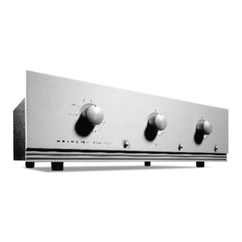
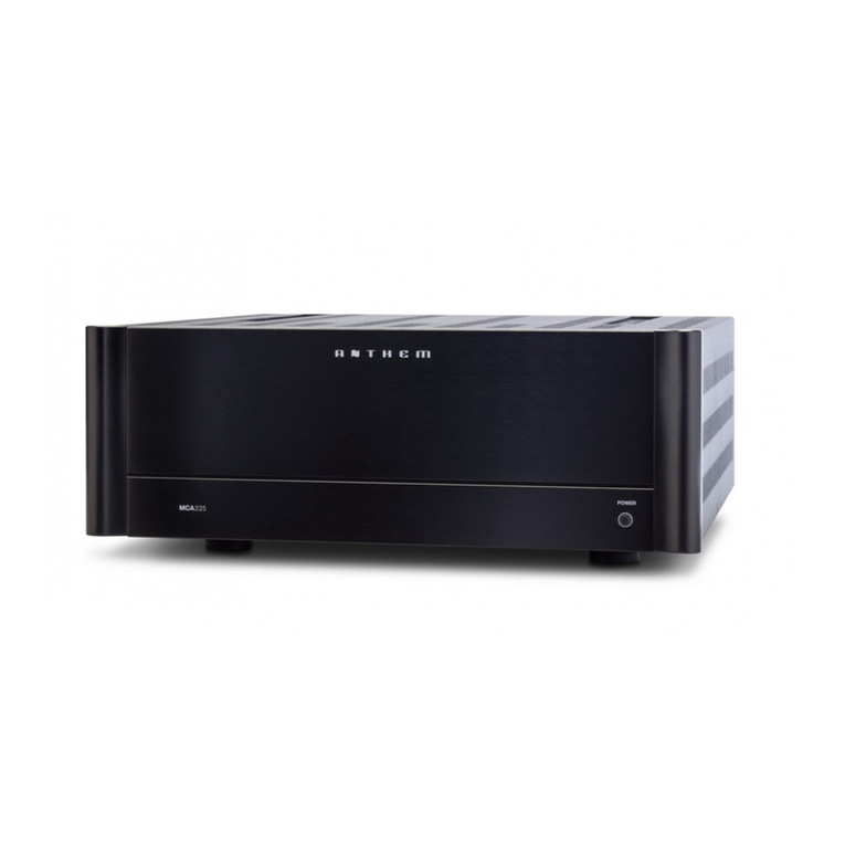
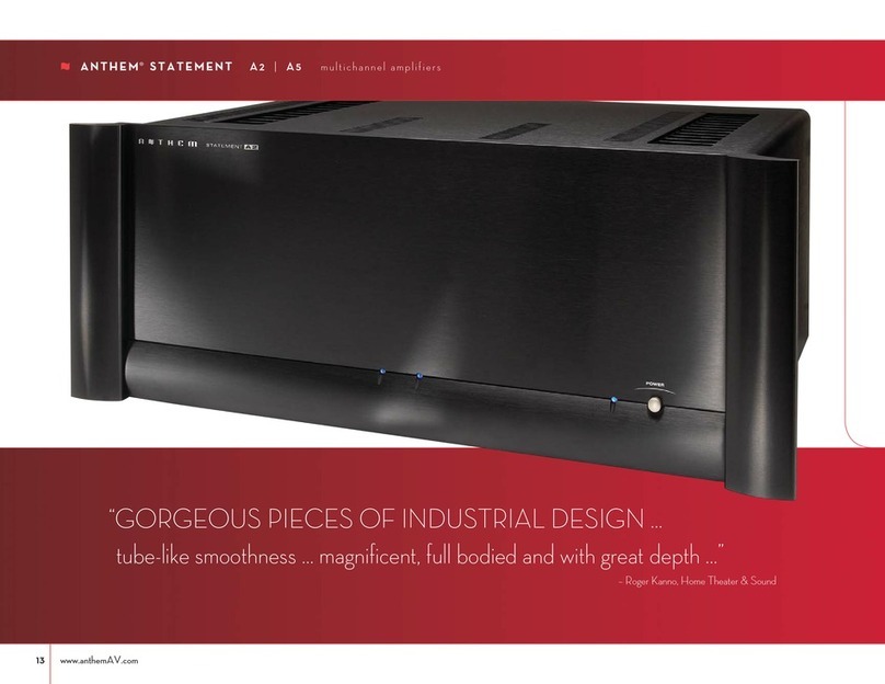
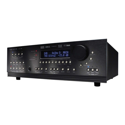
Anthem TLP 1 User manual

T L P 1
OPERATING MANUAL
w w w . a n t h e m A V . o m
™

SAFETY PRECAUTIONS
READ THIS SECTION CAREFULLY BEFORE PROCEEDING!
The lightning flash with arrowpoint within an equilateral triangle
warns of the presen e of uninsulated “dangerous voltage” within
the produ t’s en losure that may be of suffi ient magnitude to
onstitute a risk of ele tri sho k to persons.
The ex lamation point within an equilateral triangle warns users
of the presen e of important operating and maintenan e (servi ing)
instru tions in the literature a ompanying the applian e.
WARNING: TO REDUCE THE RISK OF FIRE OR ELECTRIC SHOCK, DO NOT EXPOSE THIS PRODUCT TO RAIN OR MOISTURE
AND OBJECTS FILLED WITH LIQUIDS, SUCH AS VASES, SHOULD NOT BE PLACED ON THIS PRODUCT.
CAUTION: TO PREVENT ELECTRIC SHOCK, MATCH WIDE BLADE OF PLUG TO WIDE SLOT, FULLY INSERT.
CAUTION: FOR CONTINUED PROTECTION AGAINST RISK OF FIRE, REPLACE THE FUSE ONLY WITH THE SAME AMPERAGE
AND VOLTAGE TYPE. REFER REPLACEMENT TO QUALIFIED SERVICE PERSONNEL.
WARNING: UNIT MAY BECOME HOT. ALWAYS PROVIDE ADEQUATE VENTILATION TO ALLOW FOR COOLING. DO NOT
PLACE NEAR A HEAT SOURCE, OR IN SPACES THAT CAN RESTRICT VENTILATION.
IMPORTANT SAFETY INSTRUCTIONS
WARNING: TO REDUCE THE RISK OF ELECTRIC SHOCK,
DO NOT REMOVE COVER (OR BACK). NO USER-
SERVICEABLE PARTS INSIDE. REFER SERVICING TO
QUALIFIED SERVICE PERSONNEL.
RISK OF ELECTRIC SHOCK
DO NOT OPEN
WARNING
1. R ad Instructions – All the safety and operating instru tions should be read before the produ t is operated.
2. R tain Instructions – The safety and operating instru tions should be retained for future referen e.
3. H d Warnings – All warnings on the produ t and in the operating instru tions should be adhered to.
4. Follow Instructions – All operating and use instru tions should be followed.
5. Cl aning – Unplug this produ t from the wall outlet before leaning. Do not use liquid leaners or aerosol leaners. Use
a damp, soft loth for leaning.
6. Wat r and Moistur – Do not use this produ t near water – for example, near a bath tub, wash bowl, kit hen sink, or
laundry tub; in a wet basement; or near a swimming pool; and the like.
7. Acc ssori s – Do not pla e this produ t on an unstable art, stand, tripod, bra ket, or table. The produ t may fall,
ausing serious injury to a hild or adult, and serious damage to the produ t. Use only with a art, stand, tripod, bra ket,
or table re ommended by the manufa turer, or sold with the produ t. Any mounting of the produ t should follow
manufa turer’s instru tions, and should use a mounting a essory re ommended by the manufa turer.

8. V ntilation – Slots and openings in the abinet are provided for ventilation and to ensure reliable operation of the
produ t and to prote t it from overheating, and these openings must not be blo ked or overed. The openings should
never be blo ked by pla ing the produ t on a bed, sofa, rug, or other similar surfa e. This produ t should not be pla ed
in a built-in installation su h as a book ase or ra k unless proper ventilation is provided or the manufa turer’s
instru tions have been adhered to.
9. Pow r Sourc s – This produ t should be operated only from the type of power sour e indi ated on the marking label.
If you are not sure of the type of power supply to your home, onsult your produ t dealer or lo al power ompany. For
produ ts intended to operate from battery power, or other sour es, refer to the operating instru tions.
10. Grounding and Polarization – This produ t may be equipped with a polarized alternating- urrent line plug (a plug having
one blade wider than the other). This plug will fit into the power outlet only one way. This is a safety feature. If you are
unable to insert the plug fully into the outlet, try reversing the plug. If the plug should still fail to fit, onta t your
ele tri ian to repla e your obsolete outlet. Do not defeat the safety purpose of the polarized plug.
11. Pow r-cord Prot ction – Power-supply ords should be routed so that they are not likely to be walked on or pin hed
by items pla ed upon or against them, paying parti ular attention to ords at plugs, onvenien e re epta les, and the
point where they exit from the produ t.
12. Outdoor Ant nna Grounding – If an outside antenna or able system is onne ted to the produ t, be sure the antenna
or able system is grounded so as to provide some prote tion against voltage surges and built-up stati harges. Arti le
810 of the National Ele tri al Code, ANSI/NFPA 70, provides information with regard to the proper grounding of the mast
and supporting stru ture, grounding of the lead-in wire to an antenna-dis harge unit, size of grounding ondu tors,
lo ation of antenna-dis harge unit, onne tion to grounding ele trodes, and requirements for the grounding ele trode.
13. Lightning – For added prote tion for this produ t during a lightning storm, or when it is left unattended and unused for
long periods of time, unplug it from the wall outlet and dis onne t the antenna or able systems. This will prevent
damage to the produ t due to lightning and power-line surges.
14. Pow r Lin s – An outside antenna system should not be lo ated in the vi inity of overhead power lines or other ele tri
light or power ir uits, or where it an fall into su h power lines or ir uits. When installing an outside antenna system,
extreme are should be taken to keep from tou hing su h power lines or ir uits as onta t with them might be fatal.
15. Ov rloading – Do not overload wall outlets, extension ords, or integral onvenien e re epta les as this an result in
a risk of fire or ele tri sho k.
Antenna Lead-In Wire
Antenna-Discharge Unit
(NEC Section 810-20)
Grounding Conductors
(NEC Section 810-21)
Power Service Grounding
Electronic System
(NEC ART 250. Part H)
NEC-National Electrical Code
Electrical Service
Equiptment
Ground Clamp
Ground Clamps
S2898A

16. Obj ct and Liquid Entry – Never push obje ts of any kind through openings as they may tou h dangerous voltage points
or short-out parts that ould result in a fire or ele tri sho k. Do not expose this produ t to dripping or splashing and
ensure that no obje ts filled with liquids, su h as vases, are pla ed on the produ t.
17. S rvicing – Do not attempt to servi e this produ t yourself, as opening or removing overs may expose you to
dangerous voltage or other hazards. Refer all servi ing to qualified servi e personnel.
18. Damag R quiring S rvic – Unplug this produ t from the wall outlet and refer servi ing to qualified personnel under
the following onditions:
• When power-supply ord or plug is damaged.
• If liquid has been spilled, or obje ts have fallen into the produ t.
• If the produ t has been exposed to rain or water.
• If the produ t does not operate normally by following the operating instru tions. Adjust only those ontrols that are
overed by the operating instru tions as an improper adjustment of other ontrols may result in damage and will require
extensive work by a qualified te hni ian to restore the produ t to its normal operation.
• If the produ t has been dropped or damaged in any way.
• If the produ t exhibits a distin t hange in performan e – this indi ates a need for servi e.
19. R plac m nt Parts – When repla ement parts are required, be sure the te hni ian has used repla ement parts
spe ified by the manufa turer or have the same hara teristi s as the original part. Unauthorized substitutions may
result in fire, ele tri sho k, or other hazards.
20. Saf ty Ch ck – Upon ompletion of any servi e or repairs to this produ t, ask the servi e te hni ian to perform safety
he ks to determine that the produ t is in proper operating ondition.
21. H at – The produ t should be situated away from heat sour es su h as radiators, heat registers, stoves, or other
produ ts (in luding amplifiers) that produ e heat.
Anthem, Soni Frontiers, and Paradigm are trademarks or registered trademarks of Paradigm Ele troni s In .
Copyright Paradigm Ele troni s In . All rights reserved. The information ontained herein may not be reprodu ed in whole
or in part without our express written permission. We reserve the right to hange spe ifi ations and/or features without
noti e as design improvements are in orporated.
RECYCLING AND REUSE GUIDELINES (Europe)
In a ordan e with the European Union WEEE (Waste Ele tri al and Ele troni Equipment) dire tive effe tive
August 13, 2005, we would like to notify you that this produ t may ontain regulated materials whi h, upon disposal,
require spe ial reuse and re y ling pro essing. For this reason Paradigm Ele troni s In . (the manufa turer of
Paradigm speakers and Anthem ele troni produ ts) has arranged with its distributors in European Union member
nations to olle t and re y le this produ t at no ost to you. To find your lo al distributor please onta t the dealer
from whom you pur hased this produ t or go to our website at www.paradigm. om.
Please note that only the produ t falls under the WEEE dire tive. When disposing of pa kaging and other shipping
material we en ourage you to re y le through the normal hannels.
SECTION PAGE
1. INTRODUCTION 1
1 R c iving and Unpacking th TLP 1 ......................................................1
1.1 Pa king List 1
1.2 Important Saf ty Information ............................................................1
1.2.1 Before Operating Your TLP 1 1
1.2.2 Supply Power Requirements 2
1.2.3 In-Use Noti es 2
1.3 Packing Mat rials ......................................................................2
2. CONNECTIONS AND LAYOUT 3
2.1 Quick Start Guid ......................................................................3
2.2 Front and R ar Pan l Layout ............................................................ 4
2.2.1 Front Panel Display 5
2.3 Conn ction Exampl s
2.3.1 CD Player to TLP 1 6
2.3.2 DVD Player and Satellite Re eiver to TLP 1 7
2.3.3 VCR and TV to TLP 1 8
2.3.4 TLP 1 to Amplifier and Powered Subwoofer – Small Speakers 9
2.3.5 TLP 1 to Amplifier and Powered Subwoofer – Full Range Speakers 10
2.4 R mot Control Layout ................................................................ 11
2.5 Conn cting Pow r to th TLP 1 ........................................................ 12
2.6 Audio Inputs ......................................................................... 12
2.7 Audio Outputs ........................................................................ 12
2.8 FM•AM Ant nnas .................................................................... 13
2.9 R lay Trigg r ........................................................................ 13
2.10 Infra R d R c iv r .................................................................... 13
3. FRONT PANEL OPERATION 14
3.1 Pow r On/Off .........................................................................14
3.2 Mast r Control Knob ...................................................................14
3.3 Sourc S l ction ..................................................................... 14
3.3.1 FM•AM Tuner 14
3.4 Bass / Tr bl / Balanc ................................................................15
3.5 Contour...............................................................................15
3.6 Display Brightn ss ....................................................................15
TABLE of CONTENTS

4. REMOTE CONTROL OPERATION 16
4.1 Pow ring th TLP 1 ON and OFF ........................................................ 16
4.2 Dir ct FM•AM Station Entry ........................................................... 16
4.3 Controlling Oth r Compon nts ..........................................................17
4.3.1 Entering Manufa turer’s Codes 17
4.3.2 Sear hing For a Code 17
4.3.3 Volume Lo k 17
4.4 T aching th TLP 1 R mot Control to Univ rsal L arning R mot s .........................18
App ndix A – Pr s t M mory Cod s 19
Sp cifications 21
Warranty 23
Big Pictur s of Front and R ar Pan ls Inside Ba k Cover

1
Thank you for purchasing th Anth m TLP 1 Pr amplifi r • Tun r.
Anthem Ele troni s has been manufa turing high-quality, high-end audio equipment for over a de ade. In
that time, Anthem has built an enviable reputation for produ ts that an re reate the passion a musi lover
experien es when attending a live musi al performan e, or the thrilling sound a movie buff experien es in
the very best movie theaters. Anthem equipment allows audiophiles to almost “be there” ea h and every
time they sit and enjoy musi or home theater in the omfort of their home. Anthem provides all this with the
highest level of raftsmanship, sophisti ated ir uit designs, superior quality parts and materials, modern
intuitive ergonomi s, and stylish industrial design.
Although Anthem produ ts sound great “right out of the arton”, they will sound even better after they are
thermally stabilized. We therefore re ommend that you operate this produ t for a period of time before doing
any riti al listening.
The TLP 1 is a state-of-the-art stereo preamplifier with built-in FM • AM Tuner, Re ord output with
independent input sele tion, and built-in rossover with high-pass and low-pass outputs.
1 RECEIVING AND UNPACKING THE TLP 1
The TLP 1 is shipped in a reinfor ed shipping box. Che k that you have re eived everything in the Pa king
List below and report any dis repan ies to your dealer as soon as possible. K p th invoic that you
r c iv d from your authoriz d Anth m d al r at tim of purchas – without it, s rvic cannot b giv n
und r warranty.
1.1 PACKING LIST
• TLP 1
• Remote Control
• 2 ‘AA’ Batteries
• Power Cord
• FM Antenna
• 75-ohm to 300-ohm FM Antenna Adapter
• AM Loop Antenna
• Operating Manual
1.2 IMPORTANT SAFETY INSTRUCTIONS
• The Front Panel power swit h is se ondary only; it does not dis onne t the TLP 1 from the AC
power line.
• Failing to omply with any safety instru tion, pre aution, or warning in this Operating Manual is in
dire t violation of the standards of design, manufa ture, and intended use of the produ t.
• Anthem, Soni Frontiers International, our agents, and any related party assume no liability
whatsoever for the user’s failure to omply with any or all of these requirements.
1.2.1 BEFORE OPERATING YOUR TLP 1
• Do not onne t power to the TLP 1 if there are signs of damage to its exterior.
• Do not install in an unstable lo ation or in an equipment ra k that may be at risk of ollapsing. Do
not mount to a wall or from a eiling, or in any way that poses risk of injury.
• Allow at least 6 in hes of unobstru ted air spa e above the ventilation slots in the top over of the
amplifier. Do not blo k any ventilation openings. Do not obstru t bottom vents by removing the
rubber feet or operating the amplifier dire tly on a arpet, sofa, or similar surfa e.
1. INTRODUCTION

1.2.2 SUPPLY POWER REQUIREMENTS
The TLP 1 operates from a single phase AC power sour e that supplies between 105V and 130V at a
frequen y of 60 Hz. It annot be hanged from 120V to 240V operation.
1.2.3 IN-USE NOTICES
• Use only the power supply ord with double insulation as supplied.
• Dis onne t the amplifier’s power ord before onne ting or dis onne ting any omponents.
• Do not remove the top over.
• Do not alter or modify the amplifier in any way.
• Rail fuses are not a user servi eable item.
1.3 PACKING MATERIALS
Retain the shipping box and all pa king material. They are ustom designed to prevent shipping damage from
o urring. Do not ship or transport the TLP 1 in anything other than the original box and pa king material.
1. INTRODUCTION ontinued …
2

2. CONNECTIONS AND LAYOUT
With your TLP 1 in front of you, browse through the illustrations in this se tion to see several qui k system
hookup options. It’s as simple as following the lines in the onne tion diagrams to and from ea h omponent.
2.1 QUICK START GUIDE – B for you start, mak sur all compon nts ar unplugg d.
To onne t a CD player, DVD player, TV, VCR, amplifier, and powered subwoofer to the TLP 1:
• CD Play r to TLP 1 – see diagram in se tion 2.3.1
Conne t the L/R audio output of the CD player to Analog Audio-In/CD on the TLP 1.
• DVD Play r to TLP 1 – see diagram in se tion 2.3.2
Conne t the L/R audio output of the DVD player to Analog Audio-In/DVD on the TLP 1.
• Sat llit R c iv r to TLP 1 – see diagram in se tion 2.3.2
Conne t the L/R audio output of the re eiver to Analog Audio-In/SAT•AUX on the TLP 1.
• TV to TLP 1 – see diagram in se tion 2.3.3
Conne t the L/R audio output of the TV to Analog Audio-In/SAT•AUX on the TLP 1. If you are
using a satellite re eiver and your TV does not have audio inputs and outputs, onne t the
satellite re eiver dire tly to Analog Audio-In/SAT•AUX on the TLP 1.
• VCR to TLP 1 – see diagram in se tion 2.3.3
Conne t the L/R audio output of the VCR to Analog Audio-In/VCR on the TLP 1.
To Record: Conne t Analog Audio-Out/RECORD on the TLP 1 to the L/R audio input of the VCR.
• TLP 1 to Amplifi r – see diagrams in se tions 2.3.4 and 2.3.5
From the TLP 1, onne t Left and Right outputs to the inputs of the power amplifier. Use
FULL RANGE if using full-range speakers either with or without a subwoofer, and HIGH
PASS if using speakers with limited low-frequen y response along with a subwoofer.
Follow the amplifier manufa turer’s instru tions for onne ting the speakers.
• TLP 1 to Pow r d Subwoof r – see diagrams in se tions 2.3.4 and 2.3.5
From the TLP 1, onne t Analog Audio-Out/SUBWOOFER to the subwoofer’s line/low level
input. Use FULL RANGE if the subwoofer has a built-in rossover, and LOW PASS if the
subwoofer’s rossover is bypassed or if the subwoofer doesn’t have a rossover.
Re onne t the power to all omponents and turn them on. To turn on the TLP 1 press the POWER button on
the front panel.
To List n to a CD:
• Press CD Sour e on the front panel of the TLP 1.
• Pla e a CD into the CD player and press play. You should hear musi oming from your speakers.
Use the TLP 1 Master Control Knob on the front panel to adjust volume.
To Watch a DVD:
• Press DVD Sour e on the front panel of the TLP 1.
• Sele t the TV input that orresponds to the one that the DVD player’s video output is plugged into.
• Pla e a DVD into the DVD player and press play. You should see the pi ture on your TV and hear
sound from your speakers. Use the TLP 1 Master Control Knob on the front panel to adjust volume.
3

4
2.2 FRONT AND REAR PANEL LAYOUTS
1–FM•AM Preset sele tion
2– Display
3–FM•AM Seek
4–FM•AM Tune
5–FM Stereo / Hi Blend / Mono
6– Master Control Knob:
• Volume
• Tune for FM•AM
• Setting Adjustment for Bass / Treble / Balan e;
Display Brightness; Input Level
7– Power On / Stand-By
8– Contour On/Off
9– Mute
10 – Bass / Treble settings
11 – Front Panel Remote Control IR Sensor
12 – Balan e / Display Brightness setting
13 – Headphone Ja k
14 – Re ord Path sele tion
15 – Sour e sele tion
2. CONNECTIONS AND LAYOUT ontinued …
13 12 1115 14 10 9 8 7
6542 31
1– RS-232 port (for ustom installation)*
2– FM Antenna Input
3– AM Antenna Input
4– Full Range Output (L/R ja ks)
5– High Pass Output (L/R ja ks)
6– 2 Subwoofer Outputs (Full Range)
7– 2 Subwoofer Outputs (Low Pass)
8– 2 Line Level Outputs (Re ord, Zone 2 – L/R ja ks)
9– 5 Inputs (L/R ja ks)
10 – Relay Trigger Output (3.5 mm mono ja k)
11 – Infra Red Input (3.5 mm mono ja k)
12 – Power Cord Conne tion
32
1
12 11 10 98 7654
*Custom Installers: RS-232 port is on newer produ tion TLP 1s only. Command set is available at www.anthemAV. om.

2.2.1 FRONT PANEL DISPLAY
Main Display Exampl :
1– Sour e sele tion.
2– Volume setting. When muted, “Muted” flashes instead of the urrent volume setting.
FM•AM Display Exampl :
1– Sour e+Bank. The tuner has three FM banks (FM1, FM2, and FM3) and one AM bank. The number
after the sele ted bank is the preset station.
2– FM mode. Displays “St” when in stereo, “HB” when Hi-Blend is sele ted, or “Mn” when in mono or
mono is sele ted.
3– Currently tuned FM•AM frequen y to the nearest 0.1 MHz for FM and to nearest 10 kHz for AM.
R cord Display Exampl :
1– Sour e sele tion.
2– Re ord path indi ation. Note that the sele tion time lasts approximately 3 se onds, after whi h the
normal display returns.
2. CONNECTIONS AND LAYOUT ontinued …
5
2
1
2
1
3
2
1

6
2. CONNECTIONS AND LAYOUT ontinued …
CD Player Audio Out
RL
2.3.1 CD Play r to TLP 1
CD Player
EJECT
Track 1
Amplifier

2.3.2 DVD Play r and Sat llit R c iv r to TLP 1
7
2. CONNECTIONS AND LAYOUT ontinued …
DVD Player
Composite
Video Out S-Video Out
Audio Out
RL
Digital Out
RCA Toslink
Component
Video Out
Pb
Y
Pr
SATELLITE
Amplifier
Satellite Receiver
Composite
Video Out S-Video Out
Audio Out
RL
Digital Out
RCA Toslink
Component
Video Out
Pb
Y
Pr
DVD
Not :
Conne t video output to TV.
Not :
Conne t video output to TV.

8
2.3.3 VCR and TV to TLP 1
2. CONNECTIONS AND LAYOUT ontinued …
VCR Audio
R
L
OUT IN
OUT
S-Video
Composite
IN
Video
Audio
Out
Composite
Video In Component
Video In
S-Video In
Vari Fixed
L
R
Pb
Pr
Y
Rear Panel of TV
CATV
In
VCR
EJECT
Not :
If using a satellite re eiver and a TV
monitor that does not have audio inputs
and outputs, onne t satellite re eiver’s
audio outputs dire tly to SAT•AUX.
Not :
Conne t video output to TV.
Not :
Conne t video output from
sour e omponents to TV.

PVA 2
LEFT
INPUT
RIGHT
INPUT
SERIAL NO.:
Powered Subwoofer
Level
RCA
Input
9
2.3.4 TLP 1 to Amplifi r and Pow r d Subwoof r – Small Sp ak rs
2. CONNECTIONS AND LAYOUT ontinued …
P
O
W
E
R
Not :
If subwoofer does not have a
built-in rossover, use Low Pass
output instead of Full Range.

WARNING
RISK OF HAZARDOUS ENERGY! MAKE PROPER SPEAKER CONNECTIONS. SEE OPERATING MANUAL BEFORE USING.
VA
MCA 20
2.3.5 TLP 1 to Amplifi r and Pow r d Subwoof r – Full Rang Sp ak rs
2. CONNECTIONS AND LAYOUT ontinued …
Powered Subwoofer
Level
RCA
Input
P
O
W
E
R
Not :
If subwoofer does not have a
built-in rossover, use Low Pass
output instead of Full Range.
10

11
2.4 REMOTE CONTROL LAYOUT
1– IR Transmitter (front fa e)
2– Transmission Indi ator LED (red)
3– TLP 1 Power ON
Power ON/OFF for other omponents (see #4)
Not : This does not turn the TLP 1 off (see #21)
4– Control Mode sele tion
5–FM•AM Preset sele tion (6)
6–FM•AM Preset Station Up
7–FM•AM Preset Station Down
8– Sele ts Tone Bypass
9– Sele ts Stereo / Hi Blend / Mono for FM•AM
10 – RECORD Path sele tion
11 – Contour On/Off
12 – Display Brightness
13 – Sour e sele tion
14 – Bass setting
15 – Treble setting
16 – Balan e setting
17 – • Tune for FM•AM
• Setting Adjustment Bass / Treble
• Seek for FM•AM
• Setting Adjustment for Balan e
18 –FM•AM Dire t Entry
19 – Volume Down
20 – Volume Up
21 – TLP 1 Power OFF
22 – Mute
23 – Setup (for ustomization of remote)
2. CONNECTIONS AND LAYOUT ontinued …
2
1
3
4
9
8
10
11
23
12
16
22
18
14
21
15
6
5
7
19
20
17
13

2.5 CONNECTING POWER TO THE TLP 1
Conne t the power ord to the ba k of the TLP 1 and then to an AC outlet. If ex essive hum or buzz is heard
through the speakers during operation, remove the ord from the ba k of the TLP 1 and re-insert it after
turning the onne tor upside down.
2.6 AUDIO INPUTS
Audio onne tions are made through inter onne t ables – typi ally white or bla k for the Left hannel and
red for the Right hannel. The audio output onne tors on tape re orders, VCRs, and CD players are normally
olor oded in this same manner – onne t them to the appropriate inputs on the TLP 1:
2.7 AUDIO OUTPUTS
Any of the outputs shown below an be used simultaneously:
Fix d Outputs:
These provide a fixed line-level output for onne tion to a tape re order’s or VCR’s audio re ord inputs,
and/or to an integrated amplifier or re eiver that is used for another room (Zone 2) so sour es onne ted to
the TLP 1 an be dire ted to that remote lo ation. The volume ontrol does not affe t this output level.
Subwoof r:
Intended to be used with a powered subwoofer or subwoofer amplifier, ea h of the four ja ks provides a
mono signal of the left and right hannels ombined. Up to two subwoofers an be onne ted in either of the
following onfigurations: Low Pass, whi h ontains only low bass, or Full Range, whi h is unfiltered.
• Use Full Rang if the subwoofer has a built-in rossover.
• Use Low Pass if the subwoofer’s rossover is bypassed or if there is no rossover in the subwoofer
or subwoofer amplifier.
Main:
The High Pass output redu es low bass whi h makes it ideal when using smaller speakers that are unable
to reprodu e deeper bass or bass at full output levels. The use of a powered subwoofer is strongly
re ommended with this setup. The unfiltered Full Range output is the ‘normal’ full bandwidth audio output.
• Use Full Rang if using full bandwidth speakers, either with or without a subwoofer.
• Use High Pass if using smaller speakers and a subwoofer.
12
2. CONNECTIONS AND LAYOUT ontinued …

H adphon :
When a headphone plug is inserted into the headphone ja k on the front panel, all audio
outputs on the rear panel are muted.
2.8 FM•AM ANTENNAS
To onne t the FM antenna, first onne t the two antenna wires to the
s rew terminals of the 75-ohm to 300-ohm adapter. Then onne t the
adapter to the FM ANTENNA onne tor on the TLP 1. If your lo al able
ompany provides FM servi e, onne t the able dire tly to the TLP 1
instead of using the antenna.
To onne t the AM loop antenna, press the spring-loaded tabs of the AM
ANTENNA onne tor, insert the bare ends of the wire from the loop antenna
and release the tabs.
On e the antennas are onne ted, move ea h of them around until best
re eption is found. For the FM antenna, this will usually be in a “T” formation.
2.9 RELAY TRIGGER
If your other omponents, su h as the power amplifier, have a trigger input, you an
automati ally turn them on and off simultaneously with the TLP 1. Conne t the RELAY
TRIGGER trigger output from the TLP 1 to the trigger input of your power amplifier, TV
monitor, et ., using a able with 3.5mm mono mini plugs.
2.10 INFRA RED RECEIVER
An external IR repeater allows the Remote Control to be used from other lo ations in your
home, for example Zone 2. On e a repeater is wired to a sele ted room, onne t it to the
I.R. RECEIVER input.
13
2. CONNECTIONS AND LAYOUT ontinued …
75-ohm to 300-ohm adapter

3.1 POWER ON/OFF
When turned on, the TLP 1 will have all of the same settings it had when it was last turned
off, ex ept for Volume, whi h omes on at -30 dB.
3.2 MASTER CONTROL KNOB
Besides being a Volume Control, the MASTER CONTROL KNOB also operates other fun tions, in luding
adjustment of Bass / Treble / Balan e, FM•AM tuning, Input Level, and Display Brightness sele tion.
Mut :
When MUTE is pressed, the audio output is silen ed. Press MUTE again, or rotate the Master
Control Knob to adjust the volume, and sound will return.
3.3 SOURCE SELECTION
The TLP 1 a ommodates up to five external sour es plus the built-in FM•AM stereo tuner. The main path
sele tion is ompletely independent from the re ord path sele tion.
Main Path:
To make a sour e sele tion, simply press the orresponding button.
R cord Path:
To make a sele tion for the Re ord outputs, press Re ord, then
press a sour e button within 3 se onds – the red indi ator will
remain lit for the duration of the sele tion period.
Adjust Input L v ls:
You an mat h main path input levels to ea h other to prevent large hanges in volume as you hange from
one sour e to another. Press and hold the sour e button of the input you want to adjust, and when ‘Lvl +0.0’
appears on the display, adjust using the Master Control Knob before the main display returns.
Before making input level adjustments, have all onne ted sour e omponents playing similar musi
material. Also, make sure that all four tuner banks are tuned to a station (see below). Then, as you swit h
through ea h sour e, you will hear that omponent play. This allows for easy omparative level adjustments.
Not : The sele ted tuner bank immediately hanges when pressing FM•AM. To adjust AM input level,
sele t FM-3 first, then press and hold FM•AM and the band will automati ally hange to AM.
3.3.1 FM•AM TUNER
The TLP 1 has a built-in FM • AM tuner. The station that is sele ted for the main outputs is automati ally
shared when FM•AM is sele ted for Re ord.
Manual Tuning:
Sele t the desired bank by pressing FM•AM, then press TUNE and rotate the Master Control
Knob to find a station.
Automatic Tuning:
To automati ally find the next station, press SEEK or SEEK. To s an and listen to all
available radio stations for a few se onds at a time, press and hold SEEK or SEEKfor
about a se ond. The ‘ S k’or‘S k’ indi ator on the display will hange to ‘’ or
‘’ to indi ate that the tuner is s anning. To stop s anning, press the same SEEK button
that was used to initiate s anning.
14
3. FRONT PANEL OPERATION
Other manuals for TLP 1
1
Table of contents
Other Anthem Amplifier manuals

Anthem
Anthem I225 User manual

Anthem
Anthem AVM 30 User manual

Anthem
Anthem Amp 2 User manual

Anthem
Anthem Statement P2 User manual

Anthem
Anthem TLP 1 User manual

Anthem
Anthem MCA 525 User manual

Anthem
Anthem MCA SERIES User manual

Anthem
Anthem MCA SERIES User manual

Anthem
Anthem PVA 7 User manual

Anthem
Anthem PVA 2 User manual

Anthem
Anthem Statement P2 User manual

Anthem
Anthem PVA Series User manual

Anthem
Anthem Line 1 User manual

Anthem
Anthem MCA 50 User manual

Anthem
Anthem PVA 7 User manual

Anthem
Anthem MCA 525 User manual

Anthem
Anthem STR User manual

Anthem
Anthem Integrated 2 User manual

Anthem
Anthem Statement P2 User manual

Anthem
Anthem STATEMENT A2 User manual