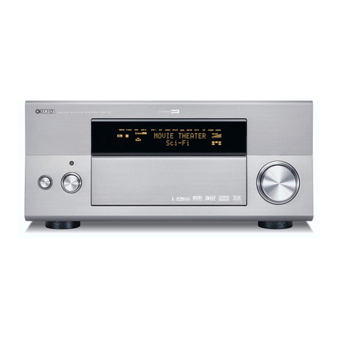
Yamaha RX-V730 User manual

SERVICE MANUAL
100800
IMPORTANT NOTICE
This manual has been provided for the use of authorized YAMAHA Retailers and their service personnel.
It has been assumed that basic service procedures inherent to the industry, and more specifically YAMAHA Products, are already
known and understood by the users, and have therefore not been restated.
WARNING: Failure to follow appropriate service and safety procedures when servicing this product may result in personal
injury, destruction of expensive components, and failure of the product to perform as specified. For these reasons,
we advise all YAMAHA product owners that any service required should be performed by an authorized
YAMAHA Retailer or the appointed service representative.
IMPORTANT: The presentation or sale of this manual to any individual or firm does not constitute authorization, certification or
recognition of any applicable technical capabilities, or establish a principle-agent relationship of any form.
The data provided is believed to be accurate and applicable to the unit(s) indicated on the cover. The research, engineering, and
service departments of YAMAHA are continually striving to improve YAMAHA products. Modifications are, therefore, inevitable
and specifications are subject to change without notice or obligation to retrofit. Should any discrepancy appear to exist, please
contact the distributor's Service Division.
WARNING: Static discharges can destroy expensive components. Discharge any static electricity your body may have
accumulated by grounding yourself to the ground buss in the unit (heavy gauge black wires connect to this buss).
IMPORTANT: Turn the unit OFF during disassembly and part replacement. Recheck all work before you apply power to the unit.
P.O.Box 1, Hamamatsu, Japan
■CONTENTS
TO SERVICE PERSONNEL .......................................... 2
IMPEDANCE SELECTOR ............................................. 2
FRONT PANELS ........................................................ 3~4
REAR PANELS ........................................................ 5~10
REMOTE CONTROL.................................................... 11
SPECIFICATIONS.................................................. 12~14
INTERNAL VIEW ......................................................... 14
DISASSEMBLY PROCEDURES/分解手順 ......... 15~18
SELF DIAGNOSIS FUNCTION (DIAG)/
自己診断機能(ダイアグ)..................................... 19~39
AMP ADJUSTMENT/アンプ部調整 ........................... 40
DISPLAY DATA ..................................................... 41~42
IC DATA ................................................................. 43~48
PIN CONNECTION DIAGRAM .................................... 49
BLOCK DIAGRAM ................................................. 50~51
PRINTED CIRCUIT BOARD .................................. 52~66
SCHEMATIC DIAGRAM ........................................ 67~74
PARTS LIST ......................................................... 75~109
REMOTE CONTROL.......................................... 110~113
Parts List for Carbon Resistors .............................. 114
AV RECEIVER/AV AMPLIFIER
RX-V730/RX-V730RDS/RX-V630/RX-V630RDS
HTR-5560/HTR-5560RDS/DSP-AX630/DSP-AX630SE
RX-V730/RX-V730RDS/RX-V630/RX-V630RDS
HTR-5560/HTR-5560RDS/DSP-AX630/DSP-AX630SE

RX-V730/RX-V730RDS/RX-V630/RX-V630RDS
HTR-5560/HTR-5560RDS/DSP-AX630/DSP-AX630SE
RX-V730/RX-V730RDS/RX-V630/RX-V630RDS
HTR-5560/HTR-5560RDS/DSP-AX630/DSP-AX630SE
14
•The variable range of the parameter (Min/Max/Step)/パラメーターの可変範囲(最小/最大/ステップ)
Parameter name Pro Logic Pro Logic II Pro Logic II 2ch DD/dts/AAC 6.1/ES Unit
Movie Music
(P.) INIT. DLY - - - 1/99/1 1/99/1 1/99/1 ms
(P.) ROOM SIZE - - - 0.1/2.0/0.1 0.1/2.0/0.1 0.1/2.0/0.1 -
(P.) LIVENESS - - - 0/10/1 0/10/1 0/10/1 -
S. DELAY - - - - 0/15/1 0/15/1 ms
S. INIT. DLY 10/25/1 10/25/1 0/15/1 0/49/1 0/49/1 0/49/1 ms
S. ROOM SIZE - - - 0.1/2.0/0.1 0.1/2.0/0.1 0.1/2.0/0.1 -
S. LIVENESS - - - 0/10/1 0/10/1 0/10/1 -
RC. INT. DLY - - - - - 1/49/1 ms
RC. ROOM SIZE - - - - - 0.1/2.0/0.1 -
RC. LIVENESS - - - - - 0/10/1 -
REV. TIME - - - 1.0/5.0/0.1 1.0/5.0/0.1 1.0/5.0/0.1 s
REV. DELAY - - - 0/250/1 0/250/1 0/250/1 ms
REV. LEVEL - - - 0/100/1 0/100/1 0/100/1 %
Panorama - OFF OFF/ON - - - -
Dimension - 0 (STD) -3/+3/1 - - - -
C. Width - 0 0/7/1 - - - -
6ch Stereo Parameter Unit
CT. LEVEL 0/100/1 %
RL. LEVEL 0/100/1 %
RC. LEVEL 0/100/1 %
RR. LEVEL 0/100/1 %
123456789 C0A
D
F
E
B
ONML JI HGK
PQ
R S
1POWER (3) P.C.B.
2POWER (1) P.C.B.
3POWER (2) P.C.B. (R, T models only)
4MAIN (6) P.C.B.
5MAIN (8) P.C.B.
6MAIN (7) P.C.B.
7MAIN (2) P.C.B.
8POWER (8) P.C.B.
9TUNER
0FUNCTION (3) P.C.B.
AFUNCTION (5) P.C.B.
BFUNCTION (2) P.C.B.
CFUNCTION (6) P.C.B.
DFUNCTION (4) P.C.B.
EFUNCTION (1) P.C.B.
FDSP P.C.B.
GMAIN (3) P.C.B.
HPOWER (4) P.C.B.
IMAIN (1) P.C.B.
JMAIN (4) P.C.B.
KPOWER (5) P.C.B.
LMAIN (9) P.C.B.
MPOWER (6) P.C.B.
NMAIN (5) P.C.B.
OOPERATION (3) P.C.B.
POPERATION (2) P.C.B.
QOPERATION (1) P.C.B.
ROPERATION (5) P.C.B.
SOPERATION (4) P.C.B.
■INTERNAL VIEW

RX-V730/RX-V730RDS/RX-V630/RX-V630RDS
HTR-5560/HTR-5560RDS/DSP-AX630/DSP-AX630SE
15
RX-V730/RX-V730RDS/RX-V630/RX-V630RDS
HTR-5560/HTR-5560RDS/DSP-AX630/DSP-AX630SE
6
6
CB307
CB441
CB443
CB442
■DISASSEMBLY PROCEDURE/分解手順
(Remove parts in the order as numbered.)
Disconnect the power cord from the AC outlet.
1. Removal of Top Cover
a. Remove 4 screws (1) and 4 screws (2). (Fig. 1)
b. Slide the Top Cover rearward to remove it. (Fig. 1)
2. Removal of Front Panel
a. Remove the BASS and TREBLE knobs (3). (Fig. 1)
b. Remove 6 screws (4) and then remove the Front
Panel. (Fig. 1)
3. Removal of Sub Chassis
a. Remove 2 push rivets (5) and then remove the Side
Plates. (Fig. 1)
b. Remove 2 screws (6) and then remove the Sub
Chassis. (Fig. 2)
c. Remove CB307, 441~443. (Fig. 2)
d. Loosen the harness fixture fixing the cable.
1. トップカバーの外し方
12
2. フロントパネルの外し方
3
4
3. サブシャーシの外し方
5
6
Fig. 2
2
2
4
4
35
51
1
Side Plate
Side Plate
Fig. 1

RX-V730/RX-V730RDS/RX-V630/RX-V630RDS
HTR-5560/HTR-5560RDS/DSP-AX630/DSP-AX630SE
RX-V730/RX-V730RDS/RX-V630/RX-V630RDS
HTR-5560/HTR-5560RDS/DSP-AX630/DSP-AX630SE
16
7
7
7
8
9
CB306
Fig. 3
0 HA EF
Fig. 4
5. FUNCTION(1)〜(6)、POWER(8)P.C.B.、
TUNERの外し方
A
B
P.C.B.チェックをする場合には
When checking the P.C.B.:
•
Put a rubber sheet and a cloth over the equipment.
Then place the P.C.B. upside down on the cloth and
check it. (Fig. 6)
•Reconnect all cables (connectors) that have been
disconnected.
•The P.C.B. removed from the rear panel no longer has
a ground connection. Be sure to connect the ground of
each P.C.B. to the chassis or GND with a jumper wire
or the like.
5. Removal of FUNCTION (1) ~ (6), POWER (8) P.C.B.s
and Tuner
a. Remove CB308. (Fig. 5)
b. Remove 25 screws (A). (Fig. 4)
c. Remove 1 screw (B). (Fig. 5)
d. Remove FUNCTION (1) ~ (6), POWER (8) P.C.B.s and
the Tuner. (Fig. 5)
4. Removal of DSP P.C.B.
a. Remove 4 screws (7) and 1 screw (8), and then
remove the Shield Case Cover. (Fig. 3)
b. Remove 2 screws (9). (Fig. 3)
c. Remove 5 screws (0). (Fig. 4)
d. Remove CB306. (Fig. 3)
e. Remove the Shield Case and the DSP P.C.B.. (Fig. 3)
4. DSPP.C.B.の外し方
78
9
0

RX-V730/RX-V730RDS/RX-V630/RX-V630RDS
HTR-5560/HTR-5560RDS/DSP-AX630/DSP-AX630SE
17
RX-V730/RX-V730RDS/RX-V630/RX-V630RDS
HTR-5560/HTR-5560RDS/DSP-AX630/DSP-AX630SE
CB308
B
MAIN (7) P.C.B.
CB253
MAIN (2) P.C.B.
MAIN (3) P.C.B.
MAIN (1) P.C.B.
MAIN (4) P.C.B.
POWER (5) P.C.B.
POWER (4) P.C.B.
MAIN (8) P.C.B.
G
D
D
C
Fig. 7
6. MAIN(1)、MAIN(3)、MAIN(4)、POWER
(4)、POWER(5)P.C.B.の外し方
CD
7. MAIN(7)、MAIN(2)P.C.B.の外し方
E
F
G
8. MAIN(8)P.C.B.の外し方
H
I
6. Removal of MAIN (1), MAIN (3), MAIN (4), POWER (4)
and POWER (5) P.C.B.s
a. Remove CB253. (Fig. 7)
b. Remove 1 screw (C) and 4 screws (D). (Fig. 7)
c. Remove MAIN (1), MAIN (3), MAIN (4), POWER (4)
and the POWER (5). (Fig. 7)
7. Removal of MAIN (7) and MAIN (2) P.C.B.s
a. Remove 3 screws (E). (Fig. 4)
b. Remove MAIN (7) P.C.B.. (Fig. 7)
c. Remove 1 screw (F). (Fig. 4)
d. Remove 1 screw (G). (Fig. 7)
e. Remove MAIN (2) P.C.B.. (Fig. 7)
8. Removal of MAIN (8) P.C.B.
a. Remove 6 screws (H). (Fig. 4)
b. Remove 1 screw (I). (Fig. 8)
c. Remove MAIN (8) P.C.B. while moving POWER (1)
P.C.B. toward the front panel side.
Fig. 6
Fig. 5
Tuner
POWER (8) P.C.B.
FUNCTION (5) P.C.B.
FUNCTION (3) P.C.B.
FUNCTION (2) P.C.B.
FUNCTION (1) P.C.B.
FUNCTION (4) P.C.B.
I
Fig. 7

RX-V730/RX-V730RDS/RX-V630/RX-V630RDS
HTR-5560/HTR-5560RDS/DSP-AX630/DSP-AX630SE
RX-V730/RX-V730RDS/RX-V630/RX-V630RDS
HTR-5560/HTR-5560RDS/DSP-AX630/DSP-AX630SE
18
パワートランジスタ、スピーカー保護リレーの交換
手順
CD
Replacement of Power Transistor, Speaker
Protection Relay
It is easy to replace the power transistor and speaker
protection relay of this unit according to the following
procedure.
a. Remove the top cover. (Refer to “1. Top Cover
Removal”on p.15.)
b. Remove 1 screw (C) and 4 screws (D). (Fig. 7)
c. Replace the flexible flat cable connecting CB253 of
MAIN (3) P.C.B. and CB308 or FUNCTION (1) P.C.B.
with the extension cable specified below. (Fig. 9)
Extension cable: MF136300
d. Raise the MAIN P.C.B. (Fig. 10)
e. In this state, the power transistor and speaker
protection relay can be replaced.
Fig. 10
CB308
CB253
Extension cable
Fig. 9

RX-V730/RX-V730RDS/RX-V630/RX-V630RDS
HTR-5560/HTR-5560RDS/DSP-AX630/DSP-AX630SE
19
RX-V730/RX-V730RDS/RX-V630/RX-V630RDS
HTR-5560/HTR-5560RDS/DSP-AX630/DSP-AX630SE
■SELF DIAGNOSIS FUNCTION (DIAG)/自己診断機能(ダイアグ)
No DIAG menu sub-menu
1 DSP THROUGH 1. ANALOG BYPASS
2. YSS 0dB
3. YSS Front 0dB
4. YSS FULL BIT
5. YSS FULL BIT F
2 RAM THROUGH RAM 0dB
3 PRO LOGIC 1. PRO LOGIC I
2. PRO LOGIC II
4 SPEAKER SET 1. MAIN: SMALL 0dB
2. CENTER: NONE
3. LFE/BASS: MAIN
4. Front Mix: 5ch
5. REAR CENTER
5 MARGIN CHECK 1. MAIN 12 dB MARGIN
2. MAIN 18 dB MARGIN
6 OTHER INPUT EXTERNAL DECODER
7 DISPLAY CHECK 1. VFD CHECK (Initial display)
2. VFD DISP OFF (All segments OFF)
3. VFD DISP ALL (All segments ON 100%)
4. VFD DIMMER (All segments ON 50%)
5. CHECKED PATTERN (ON in lattice)
8 MANUAL TEST 1. TEST ALL
2. TEST MAIN L
3. TEST CENTER
4. TEST MAIN R
5. TEST REAR R
6. TEST REAR CENTER
7. TEST REAR L
8. TEST LFE
9 FACTORY PRESET 1.
PRESET INHIBITED (memory initialization inhibited)
2. PRESET RESERVED (memory initialized)
10 AD DATA CHECK 1. PS (protection)
/FAN TEST 2. K0/K1 (panel key)
3. K2 (panel key)
4. IMP SW/POWER LIMIT
5. THM/FAN OUT
6.
FAN DRIVE TEST: HIGH (Fan test only applies to models with a fan.)
7.
FAN DRIVE TEST: MID (Fan test only applies to models with a fan.)
8.
FAN DRIVE TEST: LOW (Fan test only applies to models with a fan.)
11 IF STATUS 1. INSIDE STATUS 1 (5 Byte)
2. INSIDE STATUS 2 (3 Byte)
3. INSIDE STATUS 3 (4 Byte)
4. CHANNEL STATUS 1 (5 Byte)
5. CHANNEL STATUS 2 (5 Byte)
6. CHANNEL STATUS 3 (5 Byte)
7. CHANNEL STATUS 4 (5 Byte)
8. CHANNEL STATUS 5 (4 Byte)
9. BSI (YSS) 1 (5 Byte)
10. BSI (YSS) 2 (5 Byte)
There are 14 DIAG menu items, each of which has sub-
menu items.
Listed in the table below are menu items and sub-menu
items.

RX-V730/RX-V730RDS/RX-V630/RX-V630RDS
HTR-5560/HTR-5560RDS/DSP-AX630/DSP-AX630SE
RX-V730/RX-V730RDS/RX-V630/RX-V630RDS
HTR-5560/HTR-5560RDS/DSP-AX630/DSP-AX630SE
20
No DIAG menu sub-menu
11. BSI (YSS) 3 (5 Byte)
12. BSI (YSS) 4 (4 Byte)
13. BSI (CS) 1 (5 Byte)
14. BSI (CS) 2 (5 Byte)
15. BSI (CS) 3 (5 Byte)
16. BSI (CS) 4 (5 Byte)
17. BSI (CS) 5 (1 Byte)
18. YSS938-1 (5 Byte)
19. YSS938-2 (5 Byte)
20. YSS938-3 (4 Byte)
21. CS49329 (3 Byte)
22. Mute Trigger (5 Byte)
12 DSP RAM CHECK 1. YSS938 BUS CHECK
2. PLD/CS BUS CHECK
13 SOFT SWITCH 1. SW MODE
2. MODEL SETTING
3. TUNER DESTINATION
4. TUNER EXIST
6. RDS EXIST
7. VIDEO FORMAT
14 ROM VERSION/CHECK SUM/ 1. VERSION
PORT 2. CHECK SUM ALL/PROGRAM
3. PORT
4. AAC PORT
•Starting DIAG
Press the “STANDBY/ON”key while simultaneously
pressing those two keys of the main unit as indicated in the
figure below.
●ダイアグの起動
DSP-AX630SE
Turn on the power while pressing these keys.
Keys of main unit
except DSP-AX630SEDSP-AX630SE
Turn on the power while pressing these keys.
•Starting DIAG in the protection cancel
mode
If the protection function works and causes hindrance to
trouble diagnosis, cancel the protection function as
described below, and it will be possible to enter the DIAG
mode. (The protection functions other than the excess
current detect function will be disabled.)
Press the “STANDBY/ON”key while simultaneously
pressing those two keys indicated in the figure above. At
this time, keep pressing those two keys for 3 seconds or
longer.
In this mode, the “SLEEP”segment of the FL display of the
main unit flashes to indicate that the mode is DIAG mode
with the protection functions disabled.
●プロテクション解除モードでの起動

RX-V730/RX-V730RDS/RX-V630/RX-V630RDS
HTR-5560/HTR-5560RDS/DSP-AX630/DSP-AX630SE
21
RX-V730/RX-V730RDS/RX-V630/RX-V630RDS
HTR-5560/HTR-5560RDS/DSP-AX630/DSP-AX630SE
Opening message/
オープニング表示
DIAG menu display/
ダイアグメニュー表示
After a few seconds
Version (1 alphabet)
When there is no history
of protection function
When there is a history of protection function:
When there is a history ofprotection
function due to excess current
Version (1 alphabet)
プロテクション履歴がある場合:
CAUTION!
Using this product with the protection function disabled
may cause damage to itself. Use special care for this point
when using this mode.
•Canceling DIAG
[1] Before canceling DIAG, execute setting for PRESET of
DIAG menu No.9 (Memory initialization inhibited or
Memory initialized).
* In order to keep the user memory stored, be sure to
select PRESET INHIBITED (Memory initialization
inhibited). Protection history will remain memory.
[2] Turn off the power by pressing the “STANDBY/ON”
key of the main unit.
•Display provided when DIAG started
RX-V730/RX-V730RDS: When the monitor is connected,
DIAGNOSTIC MENU appears on its screen as shown in
the figure. (It remains on display until DIAG is cancelled.)
注意!
プロテクションを解除した状態でのダイアグモードは、
危険な状態でもプロテクションが作動しないため、動作
させると、機器を破壊することがあります。このモード
を使用する場合は十分注意してください。
●ダイアグの解除
●ダイアグ起動時の表示
プロテクション履歴がない場合:
The FL display of the main unit displays the protection
function history data and the version (1 alphabet) and the
DIAG menu [sub-menu (ANALOG BYPASS) of DIAG
menu No.1 DSP THROUGH] a few seconds later.
When there is no history of protection function:

RX-V730/RX-V730RDS/RX-V630/RX-V630RDS
HTR-5560/HTR-5560RDS/DSP-AX630/DSP-AX630SE
RX-V730/RX-V730RDS/RX-V630/RX-V630RDS
HTR-5560/HTR-5560RDS/DSP-AX630/DSP-AX630SE
22
Cause: The voltage in the power supply section is
abnormal.
Supplementary information: The abnormal voltage is
displayed in % based on 5V as 100%.
Turning on the power without correcting the abnormality
will cause the protection function to work 1 second later
and the power supply will be shut off.
When there is a history of protection
function due to abnormal voltage in
the power supply section
Version (1 alphabet)
Voltage display in %
When there is a history of protection
function due to abnormal DC output
Version (1 alphabet)
Cause: DC output of the power amplifier is abnormal.
Turning on the power without correcting the abnormality
will cause the protection function to work 3 seconds later
and the power supply will be shut off.
Cause: An excessive current flowed through the power
amplifier.
Supplementary information: As current of the power
transistor is detected, the abnormal channel can be
identified by checking the current detect transistor.
Turning on the power without correcting the abnormality
will cause the protection function to work immediately and
the power supply will instantly be shut off.
Note)
•Applying the power to a unit without correcting the
abnormality can be dangerous and cause additional
circuit damage.
•The output transistors in each amplifier channel
should be checked for damage before applying any
power.
•Amplifier current should be monitored by measuring
across the emitter resistors for each channel.

RX-V730/RX-V730RDS/RX-V630/RX-V630RDS
HTR-5560/HTR-5560RDS/DSP-AX630/DSP-AX630SE
23
RX-V730/RX-V730RDS/RX-V630/RX-V630RDS
HTR-5560/HTR-5560RDS/DSP-AX630/DSP-AX630SE
When there is a history of protection
function due to excessive heat sink
temperature
Version (1 alphabet)
Voltage display in %
Cause: The temperature of the heat sink is excessive.
Supplementary information: The abnormal voltage is
displayed in % based on 5V as 500%.
Turning on the power without correcting the abnormality
will cause the protection function to work 1 second later
and the power supply will be shut off.
* Additional causes of protection can be due to loose
connections, associated components, CPU, etc.
* For the protection voltage value, refer to DIAG menu
No.10 described later.
•Display during menu operation
During the DIAG operation, the function at work is
indicated on the FL indicator. The contents displayed
during the function operation are described in the later
section on details of functions
•History of protection function
When the protection function has worked, its history is
stored in memory with a backup. Even if no abnormality
is noted while servicing the unit, an abnormality which
has occurred previously can be defined as long as the
backup data has been stored.
The history of the protection function is cleared when
DIAG is cancelled by selecting PRESET RESERVED
(Memory initialized) of DIAG menu No.9 or when the
backup data is erased.
●プロテクションの履歴
プロテクションが働いた場合、履歴をバックアップして
記憶しています。サービスのときに異常が認められなく
ても、バックアップが残っていれば、お客様のところで
起きた異常を区別できます。
プロテクションの履歴は、ダイアグメニューNo.9で
PRESETRESERVED(メモリーの初期化)を選んでダイ
アグを解除した場合や、バックアップが消えたときには
クリアされます。
●メニュー動作中の表示

RX-V730/RX-V730RDS/RX-V630/RX-V630RDS
HTR-5560/HTR-5560RDS/DSP-AX630/DSP-AX630SE
RX-V730/RX-V730RDS/RX-V630/RX-V630RDS
HTR-5560/HTR-5560RDS/DSP-AX630/DSP-AX630SE
24
SUB-MENU selection
DIAG menu selection
RX-V730/RX-V730RDS RX-V630/RX-V630RDS/HTR-5560/HTR-556RDS/DSP-AX630
SUB-MENU selection
DIAG menu selection
Keys of remote control/リモコンキー
•Operation procedure of DIAG menu and
SUB-MENU
There are 14 MENU items, each of which has some SUB-
MENU items.
DIAG menu selection
Main unit [except DSP-AX630SE]: Select the menu using
(Forward) and (Reverse) keys of PRESET/TUNING.
Main unit [DSP-AX630SE]: Select the menu using +
(Forward) and –(Reverse) keys of SET MENU.
Remote control unit: Select the menu using (Forward)
and (Reverse) keys.
SUB-MENU selection
Main unit: Select the sub-menu using (Forward) and
(Reverse) keys of PROGRAM.
Remote control unit: Select the sub-menu using
(Forward) and (Reverse) keys.
●ダイアグメニューとサブメニューの操作
ダイアグメニューの選択
サブメニューの選択
DIAG menu selection
SUB-MENU selection
DIAG menu selection
SUB-MENU selection
except DSP-AX630SE DSP-AX630SE
Keys of main unit/本体キー

RX-V730/RX-V730RDS/RX-V630/RX-V630RDS
HTR-5560/HTR-5560RDS/DSP-AX630/DSP-AX630SE
25
RX-V730/RX-V730RDS/RX-V630/RX-V630RDS
HTR-5560/HTR-5560RDS/DSP-AX630/DSP-AX630SE
•Functions in DIAG mode
In addition to the DIAG menu items, functions as listed
below are available.
•Input selection, 6CH input
•Center/Rear/Sub-woofer level adjustment
•Muting
•Power on/off
•Master volume
* Functions related to the tuner and the set menu are not
available.
* It is possible to confirm Menu No.11 IF STATUS while
keeping the signal process (operation status) of each
DIAG menu by using the input mode key of the main
unit.
•Initial settings used to start DIAG
The following initial settings are used when starting DIAG.
When DIAG is canceled, these settings are restored to
those before starting DIAG.
•Master volume: -40dB
•Input: DVD (6CH INPUT OFF)
•Effect level: 0dB
•Audio mute: OFF
•Speaker setting: LARGE / BASS OUT = BOTH
•DIAG menu: DSP THROUGH (1. ANALOG BYPASS)
●ダイアグ中の機能
●ダイアグ開始時の初期設定

RX-V730/RX-V730RDS/RX-V630/RX-V630RDS
HTR-5560/HTR-5560RDS/DSP-AX630/DSP-AX630SE
RX-V730/RX-V730RDS/RX-V630/RX-V630RDS
HTR-5560/HTR-5560RDS/DSP-AX630/DSP-AX630SE
26
YSS Front 0dB
•The front CH signal including the head margin is output
at the main CH.
Head margin:
Main L/R: 0dBFS, Center: -6dBFS,
RL/RR: -12dBFS, SWFR: Add L/R signal at -20dBFS.
Reference data
INPUT: DVD ANALOG
SWFR: 50Hz, Others: 1kHz
YSSFront0dB
•Details of DIAG menu
With full-bit output specified in some modes, it is possible
to execute 0dBFS output without head margin in each
channel.
1. DSP THROUGH
Main DSP of YSS938 is selected for MAIN L/R output.
ANALOG BYPASS
•The signal for L/R is output as it is without passing
through the DSP section.
Reference data
INPUT: DVD ANALOG
SWFR: 50Hz, Others: 1kHz
●ダイアグメニュー詳細
1. DSPTHROUGH
ANALOGBYPASS
YSS 0dB
•The signal is output including the head margin.
Head margin:
Main L/R: 0dBFS, Center: 0dBFS,
RL/RR: -12dBFS, SWFR: Add L/R signal at -20dBFS.
Reference data
INPUT: DVD ANALOG
SWFR: 50Hz, Others: 1kHz
YSS0dB
Input level Volume SPEAKER OUTPUT (1kHz) SUBWOOFER
MAIN L/R CENTER
REAR CENTER
RL/RR OUTPUT (50Hz)
Both ch, -20 dBV -10 dB +14.3 dBV - ∞- ∞- ∞- ∞
Input level Volume SPEAKER OUTPUT (1kHz) SUBWOOFER
MAIN L/R CENTER
REAR CENTER
RL/RR OUTPUT (50Hz)
Both ch, -20 dBV -10 dB +14.0 dBV +14.0 dBV +14.0 dBV +14.0 dBV -2.5 dBV
Input level Volume SPEAKER OUTPUT (1kHz) SUBWOOFER
MAIN L/R CENTER
REAR CENTER
RL/RR OUTPUT (50Hz)
Both ch, -20 dBV -10 dB +14.0 dBV - ∞- ∞- ∞- ∞

RX-V730/RX-V730RDS/RX-V630/RX-V630RDS
HTR-5560/HTR-5560RDS/DSP-AX630/DSP-AX630SE
27
RX-V730/RX-V730RDS/RX-V630/RX-V630RDS
HTR-5560/HTR-5560RDS/DSP-AX630/DSP-AX630SE
YSS FULL BIT
•The signal is output in digital full bit without including
the head margin.
•The SWFR signal is output but not in digital full bit.
Reference data
INPUT: DVD ANALOG
SWFR: 50Hz, Others: 1kHz
YSS FULL BIT F
•The front CH signal is output in digital full bit at the main
CH.
Reference data
INPUT: DVD ANALOG
SWFR: 50Hz, Others: 1kHz
YSSFULLBIT
YSSFULLBITF
Input level Volume SPEAKER OUTPUT (1kHz) SUBWOOFER
MAIN L/R CENTER
REAR CENTER
RL/RR OUTPUT (50Hz)
Both ch, -20 dBV -10 dB +14.6 dBV +14.4 dBV +14.0 dBV +14.5 dBV -2.5 dBV
Input level Volume SPEAKER OUTPUT (1kHz) SUBWOOFER
MAIN L/R CENTER
REAR CENTER
RL/RR OUTPUT (50Hz)
Both ch, -20 dBV -10 dB +14.0 dBV - ∞- ∞- ∞- ∞
A/D
DIR
YSS938
Main DSP
DD/dts
Sub DSP
Through
CS49329
L/R
C
RC/SW
FL/FR
RL/RR
Analog
Digital
L/(L+R)/2
L/R
L/R
L/R
L/–
DSP THROUGH ~
YSS (Analog/PCM)

RX-V730/RX-V730RDS/RX-V630/RX-V630RDS
HTR-5560/HTR-5560RDS/DSP-AX630/DSP-AX630SE
RX-V730/RX-V730RDS/RX-V630/RX-V630RDS
HTR-5560/HTR-5560RDS/DSP-AX630/DSP-AX630SE
28
A/D
DIR
YSS938
Main DSP
Thr/DD/dts
Sub DSP
Through
CS4932X
4Mbit DRAM
Analog
Digital
L/R
C
RC/SW
FL/FR
RL/RR
RAM THROUGH ~
(Auto)
2. RAM THROUGH
This function is for YSS938 only.
Only the CT signal is output through the Sub DSP - DRAM.
RAM 0dB
2. RAMTHROUGH
RAM0dB
Reference data
INPUT: DVD ANALOG
SWFR: 50Hz, Others: 1kHz
Input level Volume SPEAKER OUTPUT (1kHz) SUBWOOFER
MAIN L/R CENTER
REAR CENTER
RL/RR OUTPUT (50Hz)
Both ch, -20 dBV -10 dB - ∞+14.0 dBV - ∞- ∞- ∞

RX-V730/RX-V730RDS/RX-V630/RX-V630RDS
HTR-5560/HTR-5560RDS/DSP-AX630/DSP-AX630SE
29
RX-V730/RX-V730RDS/RX-V630/RX-V630RDS
HTR-5560/HTR-5560RDS/DSP-AX630/DSP-AX630SE
3. PRO LOGIC
The L/C/R/RL/RR signals undergo the Pro-Logic
processing and C/RL/RR signals are output through Sub
DSP-DRAM. Main DSP is selected for MAIN L/R output.
Using the sub-menu, it is possible to select PRO LOGIC I,
II (Movie). The Auto Input Balance function is always off.
The LFE signal is not output when decoding in the PRO
LOGIC I, II mode.
PRO LOGIC II
Reference data
INPUT: DVD ANALOG
SWFR: 50Hz, Others: 1kHz
Reference data
INPUT: DVD ANALOG
SWFR: 50Hz, Others: 1kHz
3. PROLOGIC
III
III
PROLOGICII
PRO LOGIC IPROLOGICI
Input level Volume SPEAKER OUTPUT (1kHz) SUBWOOFER
MAIN L/R CENTER
REAR CENTER
RL/RR OUTPUT (50Hz)
Each ch, -20 dBV -10 dB +14.2 dBV - ∞- ∞- ∞- ∞
Both ch, -20 dBV -10 dB - ∞+17.0 dBV - ∞- ∞- ∞
Input level Volume SPEAKER OUTPUT (1kHz) SUBWOOFER
MAIN L/R CENTER
REAR CENTER
RL/RR OUTPUT (50Hz)
Each ch, -20 dBV -10 dB +14.2 dBV - ∞- ∞- ∞- ∞
Both ch, -20 dBV -10 dB - ∞+17.0 dBV - ∞- ∞- ∞
L/R
C
RC/SW
FL/FR
RL/RR
A/D
DIR
YSS938
Main DSP
Pro Logic I/II
or DD
Sub DSP
Through
CS49329
AAC
4Mbit DRAM
Analog
Digital
Dolby Pro Logic (Auto)

RX-V730/RX-V730RDS/RX-V630/RX-V630RDS
HTR-5560/HTR-5560RDS/DSP-AX630/DSP-AX630SE
RX-V730/RX-V730RDS/RX-V630/RX-V630RDS
HTR-5560/HTR-5560RDS/DSP-AX630/DSP-AX630SE
30
4. SPEAKERS SET
The input signal is automatically identified and switched in
the priority order of dts →DOLBY DIGITAL →AAC →
PCM AUDIO →Analog (A/D) according to the signal
detection.
The signals output from the DSP block are the same as 1.
DSP THROUGH: YSS 0dB.
LARGE: This mode is used with a speaker with high
bass reproduction performance (a large
unit). Full bandwidth signals are output.
SMALL: This mode is used with a speaker with low
bass reproduction performance (a small
unit). The signals of 90Hz or less are mixed
into the channel specified by LFE/BASS.
NONE: This mode is used with no center speaker.
The center content is reduced by 3dB and
distributed to MAIN L/R.
The analog switch settings for each sub-menu are as
shown in the table below.
MAIN: SMALL 0dB
Front Mix: 5ch
REAR CENTER
LFE/BASS:MAIN
4. SPEAKERSSET
Sub-menu
CENTER SP REAR SP MAIN SP
MAIN LEVEL
LFE/BASS
1 MAIN: SMALL 0dB LARGE LARGE SMALL 0dB SWFR
2 CENTER: NONE NONE LARGE LARGE 0dB BOTH
3 LFE/BASS: MAIN SMALL SMALL LARGE 0dB MAIN
4 FRONT MIX: 5CH LARGE LARGE LARGE 0dB BOTH
5 REAR CENTER: POWER LARGE LARGE LARGE 0dB BOTH
Reference data
INPUT: DVD ANALOG (Both ch)
Sub-menu Input level Volume SPEAKER OUTPUT (1kHz) SUBWOOFER
MAIN L/R CENTER
REAR CENTER
RL/RR
OUTPUT (50Hz)
1 MAIN: SMALL 0dB
1kHz/90Hz Both ch, -20 dBV
-10 dB
+14.8/+11.5 dBV
- ∞- ∞- ∞- ∞
2 CENTER: NONE
1kHz Both ch, -20 dBV
-10 dB +11.9 dBV - ∞- ∞- ∞- ∞
3 LFE/BASS: MAIN
50Hz Both ch, -20 dBV
-10 dB +13.0 dBV - ∞- ∞- ∞- ∞
4 FRONT MIX: 5CH
1kHz Both ch, -20 dBV
-10 dB +19.0 dBV - ∞- ∞- ∞- ∞
5
REAR CENTER: POWER
1kHz Both ch, -20 dBV
-10 dB - ∞- ∞+14.0 dBV - ∞- ∞

RX-V730/RX-V730RDS/RX-V630/RX-V630RDS
HTR-5560/HTR-5560RDS/DSP-AX630/DSP-AX630SE
31
RX-V730/RX-V730RDS/RX-V630/RX-V630RDS
HTR-5560/HTR-5560RDS/DSP-AX630/DSP-AX630SE
5. MARGIN CHECK
The signal is output including the head margin.
MAIN 12dB MARGIN
5. MARGINCHECK
MAIN12dBMARGIN
Reference data
INPUT: DVD ANALOG
SWFR: 50Hz, Others: 1kHz
MAIN 18dB MARGIN MAIN18dBMARGIN
Reference data
INPUT: DVD ANALOG
SWFR: 50Hz, Others: 1kHz
L/R
C
RC/SW
FL/FR
RL/RR
A/D
DIR
YSS938
Main DSP
Thr/DD/dts
Sub DSP
Through
CS49329
Analog
Digital
Input level Volume SPEAKER OUTPUT (1kHz) SUBWOOFER
MAIN L/R CENTER
REAR CENTER
RL/RR OUTPUT (50Hz)
Both ch, -20 dBV -10 dB +17.0 dBV - ∞- ∞- ∞- ∞
Input level Volume SPEAKER OUTPUT (1kHz) SUBWOOFER
MAIN L/R CENTER
REAR CENTER
RL/RR OUTPUT (50Hz)
Both ch, -20 dBV -10 dB +14.0 dBV - ∞- ∞- ∞- ∞

RX-V730/RX-V730RDS/RX-V630/RX-V630RDS
HTR-5560/HTR-5560RDS/DSP-AX630/DSP-AX630SE
RX-V730/RX-V730RDS/RX-V630/RX-V630RDS
HTR-5560/HTR-5560RDS/DSP-AX630/DSP-AX630SE
32
6. OTHER INPUT
The signal input through the 6CH INPUT terminals is
output.
EXTERNAL DECODER
6. OTHERINPUT
EXTERNALDECODER
Reference data
INPUT: 6CH INPUT
SWFR: 50Hz, Others: 1kHz
Initial display / All segments OFF / All segments ON (dimmer 100%) /
All segments ON (dimmer 50%) /
Lighting of segments
in lattice /
Lighting in lattice /
Normal / Short /
7. DISPLAYCHECK
Segment conditions of the FL driver and the FL tube are
checked by turning ON and OFF all segments. Next, the
operation of the FL driver is checked by using the dimmer
control. Then a short between segments next to each
other is checked by turning ON and OFF all segments
alternately (in lattice). (In the above example, the
segments in the second row from the top are shorted.)
7. DISPLAY CHECK
This program is used to check the FL display section. The
display condition varies as shown below according to the
sub-menu operation. The signals are processed using
EFFECT OFF (The L/R signal is output using ANALOG
MAIN BYPASS.)
Input level Volume SPEAKER OUTPUT (1kHz) SUBWOOFER
MAIN L/R CENTER
REAR CENTER
RL/RR OUTPUT (50Hz)
Both ch, -20 dBV -10 dB +14.3 dBV +14.3 dBV - ∞+14.3 dBV -7.5 dBV
Other manuals for RX-V730
2
This manual suits for next models
7
Table of contents
Other Yamaha Amplifier manuals

Yamaha
Yamaha M-65 User manual

Yamaha
Yamaha XH150 User manual

Yamaha
Yamaha M-50 User manual

Yamaha
Yamaha DSP-A2 User manual

Yamaha
Yamaha DG100-212 User manual

Yamaha
Yamaha MX-800/L User manual

Yamaha
Yamaha C 160 User manual

Yamaha
Yamaha A-1020 User manual

Yamaha
Yamaha AVC-30U User manual

Yamaha
Yamaha AX-596 User manual

Yamaha
Yamaha P4050 User manual

Yamaha
Yamaha A-S3000 User manual

Yamaha
Yamaha A-U671 User manual

Yamaha
Yamaha PC4800N User manual

Yamaha
Yamaha KPA-501 User manual

Yamaha
Yamaha A-S1100 User manual

Yamaha
Yamaha M-2 User manual

Yamaha
Yamaha PC1602 User manual

Yamaha
Yamaha DSP-A990 User manual

Yamaha
Yamaha AVX-700 User manual