CONGRATULATIONS!
Your
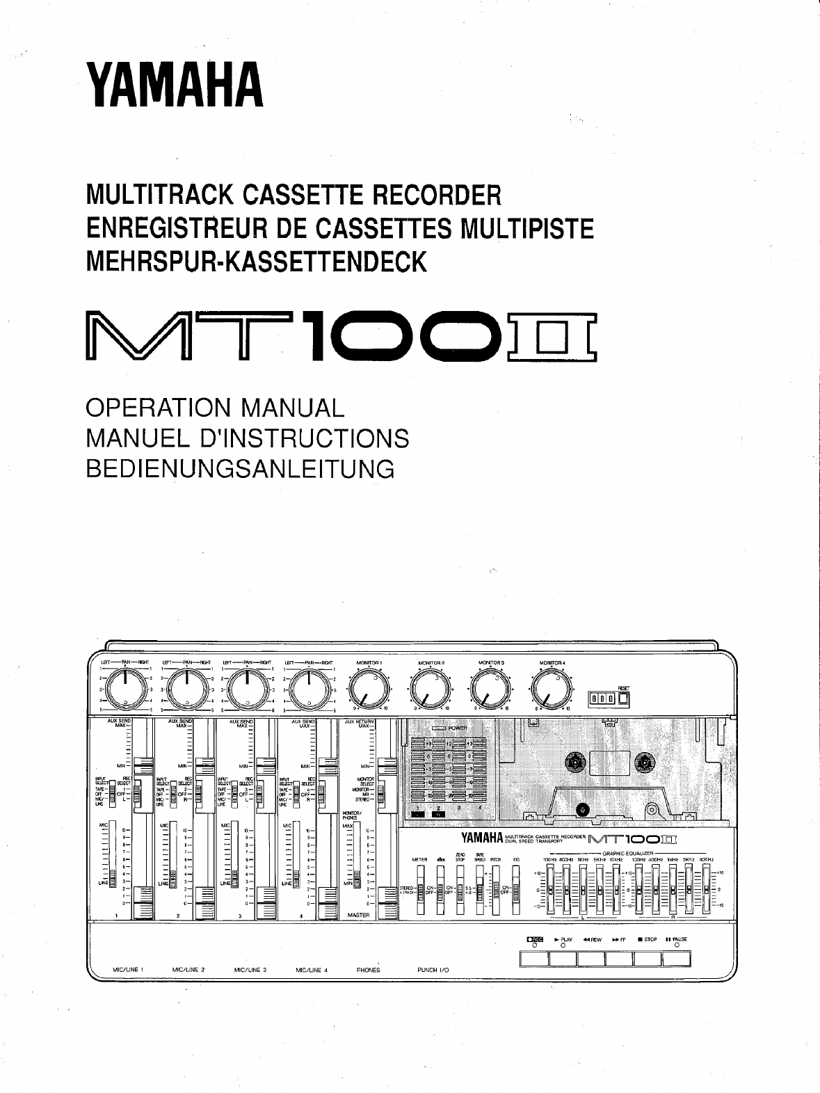
МТ10ОП
Multitrack
Cassette
Recorder
is
a
powerful
recording
tool that
will
enable
you
to
work
with
sound
in
many
ways.
No
other
multitrack
cassette
recorder
offers
the
straightforward
simplicity
and
ease-of-use
of
the
MTIOOH.
Whether
you
need
to
record
acoustic
instruments
or
voice
using
microphones,
electronic
instruments
and
line-level
sources,
or
a
creative
blend
of
the
two,
the
МТІ0ОП
makes
the
process
of
building
tracks
extraordinarily
smooth
and
simple.
You
can
simply
record
and
remix
four
tracks,
or
use
the
multitrack
“ping-pong”
recording
technique
to
in-
dividually
record
up
to
ten
independent
parts
—
adding
sound
layer
by
layer
until
you
create
exactly
the
arrangement
and
texture
your
imagination
demands
with
its
ability
to
record
on
all
four
tracks
at
once,
or
in
any
conbination,
MT100II
is
the
ideal
choice
for
recording
bands
or
layering
tracks
at
home.
And,
because
it's
a
YAMAHA,
you
know
that
the
MTIOOII
will
give
you
the
very
finest
sound
quality
and
overall
performance
available.
In
order
to
make
use
of
the
MTIOOII's
many
features
and
obtain
maximum
performance,
we
urge
you
to
read
this
operation
manual
thoroughly
—
and
keep
it
in
a
safe
place
for
later
reference.
CONTENTS
PRECAUTIONS
.........................................
1
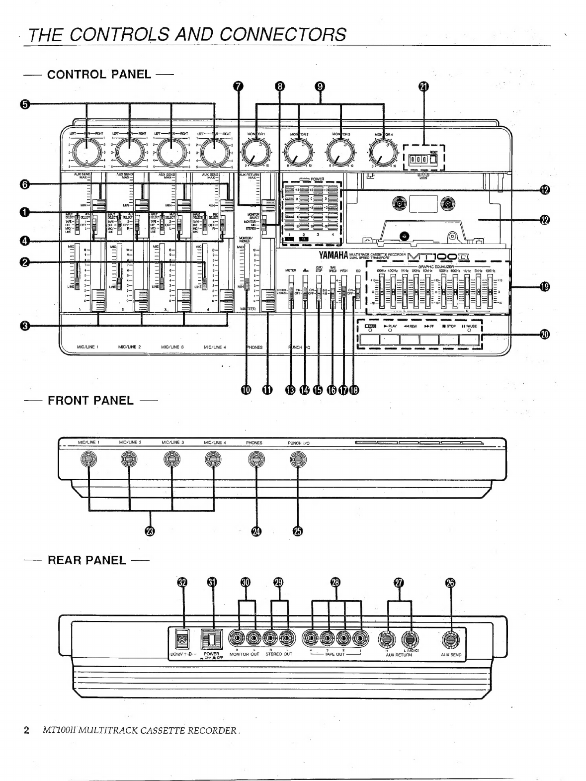
THE
CONTROLS
AND
CONNECTORS
.....................
2
MT100II
CONTROLS
AND
THEIR
FUNCTIONS
..................
2
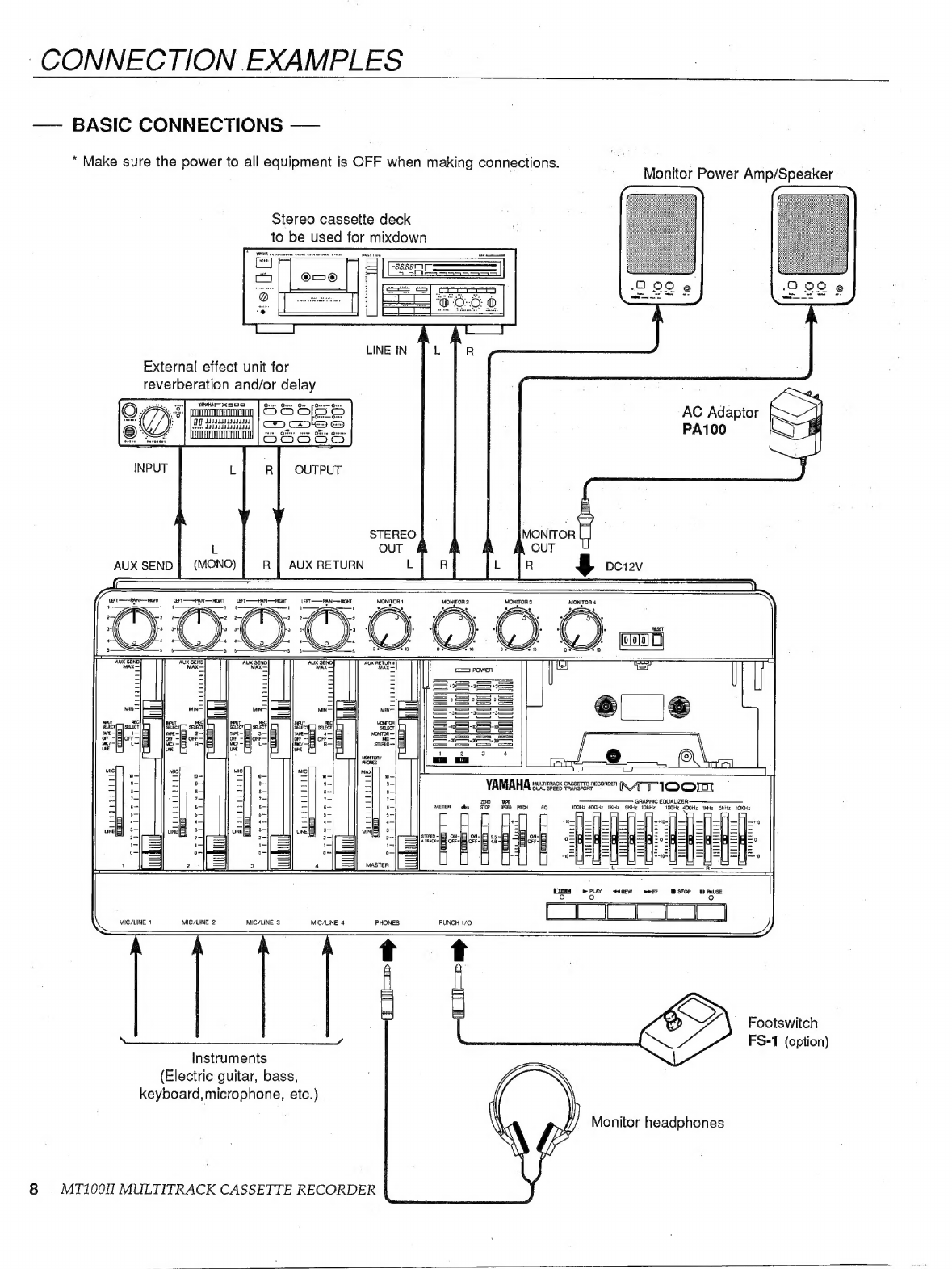
CONNECTION
EXAMPLES
...............................
8
ABOUT
CASSETTE
ТАРЕ8...............................
9
THE
RECORDING
PROCESS
............................
10
RECORDING
THE
FIRST
TRACK
.........................
11
STEP
1:
CHANNEL-TO-TRACK
ASSIGNMENT
.................
11
STEP
2:
MONITOR
SETUP
..................................
12
STEP
3:
SETTING
RECORDING
LEVELS
......................
13
ЗТЕРИ
RECORD
nn
nn
13
OVERDUBBING:
с.
oro
cx
ne
ew
oe
ee
14
PING-PONG
RECORDING
...............................
15
A
PING-PONG
RECORDING
EXAMPLE
.......................
16
MIXDOWN
weh
wa
wx
rs
sats
eas
bie
deb
ied
бата
17
USING
THE
GRAPHIC
EQUALIZER
.......................
18
USING
THE
TAPE
OUT
JACKS
..........................
19
USING
THE
AUX
SEND/RETURN
LOOP
...................
20
PUNCH-IN/OUT
RECORDING
............................
21
MAINTENANCE
`.
"rre
22
SPECIFICATIONS
ana
u
23
BLOCK
DIAGRAM
.....................................
77