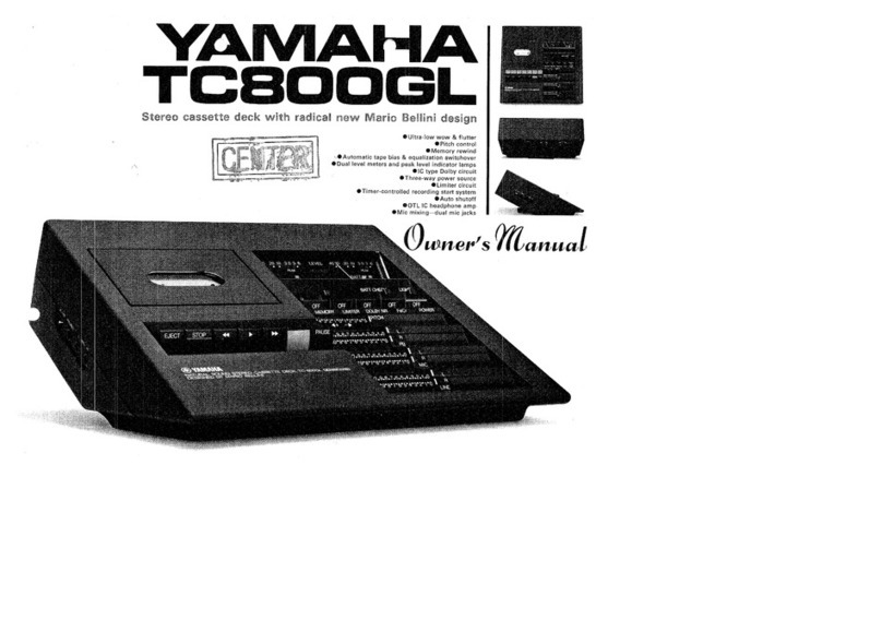
Yamaha TC800GL User manual

www.SteamPoweredRadio.Com
Stereo
cassette deck
with
radical
new
Mario
Bellini design
•
Ultra
-
low
wow
&
flutter
• Pitch
control
•
Memory
rewind
•
Automatic
tape bias
&
equalization
switchover
• Dual level meters and peak level
indicator
lamps
•
IC
type
Dolby
circuit
•Three-
way
power
source
•
Limiter
circuit
•
Timer-controlled
recording
start
system
eAuto
shutoff
eOTL
IC
headphone
amp
•
Mic
mixing
-dual
mic
jacks
<9wner'
s
manual

www.SteamPoweredRadio.Com
Professional
recording
&
control
convenience.
Professional
performance
for
your
stereo
system.
I'
t
....
I
I._
..
~
'-
-
,..
·-i.
...
,..
. \ - A
I t
·l
1
1
-f
A
perfe
c
tly
balan
ced
fly
wheel
and
precisi
on
tape
tr
ans
po
rt
mechani
sm.
Cap
st
an
roundne
ss
and
s
urfa
ce
eve
nne
ss
tol
er
ances
twi
ce
as s
tring
ent as
oth
er
manufa
c
tur
ers
-
within
1
11
. Close
ly
r
egulated
caps
tan cl
earance
and
angle
.
1
It
all
adds
up
to
less
than
0.06
°~ (w r
ms
)
wow
&
flutt
er,
and
an
outstanding
58d8
s
ig
nal-t
o-no
ise
ratio (Dol
by
on
).
Th
e TC-BOOGL is
also
a
triumph
of
s
tyling
an
d s
tereo
engineering
.
Lyin
g
fl
at
or
tilted
forward
on
it
s
fo
ld
-o
ut
s
upp
o
rt
,
it
o
ff
ers
full
con
tr
ol
conven
i
ence
and
visibi
lit
y
fr
om
an
y
operator
p
os
iti
on:
stan
d
ing,
si
tting
or
reclin
i
ng
.
..
.
Three
-
Way
-
Power
Versati
l
ity
AC
l
ine
, 12V
ex
t
erna
l
source,
or
bat
t
eries
in
th
e
built
-in
com
partme
nt. P
owe
r
the
TC
-BOOGL
wi
th
any
of
th
e three;
use
it
at
h
ome
as a
part
of
your
st
ereo
sys
tem
,
in
your
car
or
boat
,
or
as a
port
ab
le
un
it
fo
r l
ive
reco
rding
and
outdoor
listen
ing
.
Automatic
Recording
with
Timer
Plug
th
e
power
cord
into
your
ti
mer
, s
et
up
fo
r re
cording
and
pr
ess
the
Pause
switch
.
When
the
set
ti
me
arrives,
po
wer
to
th
e
unit
will
pop
ou
t
the
Pause
sw
i
tch
and
re
co
rding
wi
ll
begin
(
AC
operation
only).
Super
-
Hard
Permalloy
Rec
/PB
Head
In a
ddit
ion to a special
materi
al
and
co
n
st
ruc
ti
on
which
offers
s
up
e
rb
durabil
ity
and
extended
se
rvi
ce
life,
thi
s head
also
fea
tures
excel
l
en
t sen
sitivity,
an
ou
t
stand
ing
dynamic
r
ange
and
high
s
ign
al-t
o-
noise
ratio
.
It
is
also
one
of
th
e reasons
behind
the
TC-BOO
GL
's
ul
tr
a-
l
ow
di
s
tor
tion.
Reset
the
t
hree
-d
igit
t
ape
co
unt
er
to
zero
and
pres
s
the Me
mory
butt
on
.
Th
en, w hen
you
re
wind
,
the
tape
will
st
op
at
999
to
t you begin
play
at
ze
ro.
Great
for
reh
ear
ing
favorite
pass
age
s,
language
s
tudy,
et
c.
Automatic
Tape
Switchover
For c
hr
ome
casse
tt
es
wi
th the
new
e
xt
ra
ho
le, a
specia
l sensor
a
ut
oma
ti
cally
switches
bias
and
equ
alization,
matching
the
tape
characteristics. A
manual
selector
lets you
swi
tch
back
and
forth
be
tw
een r
eg
ul
ar
casse
tt
es
and
fe
rr
i-chrome
(F
eCr
) types
Limiter
Ci
rcuit
Ideal
for
limiting
pe
ak
s
ur
ges
duri
ng
live
rec
ordin
g,
th
is
c
ir
cui
t
compresses s
ignal
s w
hic
h threaten
to s
aturate
th
e
recor
din
g
sys
tem,
th
us avoi
di
ng clippi
ng
and
over
l
oad
dist
or
tion.
Th
e
swi
t
ch
can also be
used
with
a
hi
gh i
np
ut
l
eve
l se
tt
ing
for
aut
oma
ti
c level
contro
l; ideal
for
rec
ord
ing
speeches,
confe
rences,
et
c.
Extended
-
Range
Level
Meter
s,
LED
Peak
Indicator
s
Each m
eter
has
an
extra
-
wide
range
of -4
0d
8 to +
6d8,
for
full
visual
v
er
if
ication
of
even
the
most
dy
namic
su
rges
.
There
are
also
l
ong-
l
ife
LED
in
dicators
to
assure
pe
rf
ec
t rec
or
ding
con
t
ro
l.
One
indi
cat
or
lights
fo
r l
eve
ls
above
-3d
8
a
nd
th
e
oth
er
for
l
eve
ls
above
'
4d8.
IC
Dolby
Circuit
Th
e
Dolby
noise
reduction
sys
t
em
cuts
background
noise
and
tape hiss
by
first
boost
ing
the
treble
recording
signal
during
sof
t passages,
then
reducing
the
same
passage
signals
(
and
recorded
noise
)
dur
i
ng
playback.
In
the
TC-BOOGL the
system
is
aided
by
integrated
circuitry
for
better
signal-to-noise
rat
io
and
lowe
r
distortion.
Pitch
Control
"Tune"
you
r
cassettes
to
a
piano,
organ,
etc.,
by
moving
the
slider
left
or right.
Up
to
3"o
playback
speed
adjustment
is
provided
by
a special
servo
circuit.
This
is
the
i
deal
recording
range,
so
perfect
recordings
are
easy
every
time.
Full
Auto
Shutoff
At
the
end
of
a
tape
(
recording
or
pl
ayback
)
the
set
automatically
shuts
off,
to
protect
the
capstan
and
pinch
roll
er
against
deformation
.

www.SteamPoweredRadio.Com
Mic
Mixing
Mario
Bellini Design
The
TC-800GL
concept
was
created
for
Yamaha
by
the
world
-
famous
designer,
Mario
Bellini. He also teamed up
with
our
technicians
to
develop
an
all-new
series
of
orthodynamic
headphones
.
Their
lightweight
comfort
and
thrilling
performance
provide
an
extra
measure
of
music
enjoyment
during
private
listening.
This
feature
lets you be
your
own
disc
jockey,
or
add
your
part
to
.
music
minus
one
recordings
.
The
dual
mic
inputs
work
with
the
level
indicators and separate Line and
Mic
controls
for
a
perfect
balance
of
mixed
signals.
thanks
to
this
special
circuit
design
usually
reserved
for
only
the
most
expensive
integrated
power
amplifiers
.
It
assures
full
frequency
response and
ultra-low
distortion
at
any
listening
level.
OTL Integrated Circuit
Headphone Amp
Snap-Off
Cassette Pocket
Headphone
listening
(via
low
or
high
impedance
headphones
)
provides
supefb
tonal
clarity,
To clean
the
heads and
tape
transport
system,
just
snap
off
the
cassette
cover
for
ful
l,
easy
access.
SPECIFICATIONS:
-----
- -
--------------------
Recording System
Tape Speed
Wow
& Flutter
Signal-to-Noise
Ratio
Total
Distortion
Frequency Response
Bias Frequency
Input
Sensitivity
/
lmpedence
Channel Separation
Playback Pitch
Control
For
details
please
contact
4-Track, 2-Channel Stereo
4.
8cm
/sec (1½ ips)
Less than 0.
06
% (
WRMS
)
Less than 0
.2
% DIN
Better than
50dB
(DIN, OdB)
Better
than
58dB
(
Dolby
On)
Less than 1.5% (1KHz, OVU)
30
-
13,000Hz
(
LH
Tape)
30-15,000Hz
(
Cr02
Tape)
85KHz
Line:
50mV
/
50K!1
Mic
: 0.
5V
/
10K!1
Better
than
30dB
± 3%
Output
Level/
Impedance
Fast
Wind,
Rewind
Time
Se
miconductors
Power
Consumption
Power
Source
Dimensions
(W x H x D)
Weight
Line:
0.4V
(OVU)
Headphone: 1
mW
/8!1,
3mW
/
150
!1
Within
80
Seconds
(
C-60
Tape)
45
Transistors
, 6 ICs,
38
Diodes
16W
U.S.A. & Canada: 117V,
60Hz
Europe:
220
/
240V
,
50Hz
Other
Areas:
117
/
220
/
240V,
50
/
60Hz
DC
12V
(
UM
-2 batteries x 9)
312 x
98
x
312mm
(12¼" X 3¾" X 12
¼"
)
5Kg
(
11
lbs.)
without
batteries
Specif
icati
ons
subject
to
change
wi
thout
not
i
ce
. Dolby is a trademark
of
D
olby
laboratories, Inc.
SINCE
1887
.
YAMAHA
NIPPON GAKKI
CO
.,
LTD., HAMAMATSU, JAPAN
□ YAMAHA INTERNATIONAL CORPORATION
..._
P.O. Box
6600
, Buena Park, Calif.
90620
U.S.A.
□
YAMAHA
AUDIO
1330
Portage
Ave
.,
Winnipeg,
Man
.
R3G
OV6
Canada
□
YAMAHA
EUROPA G.m.b.H.
2084
Rellingen b. Hamburg, Siemensstr.
22-34
West Germany
IA-
82R
)
75950
@ 4
Prin1
cd
in
Japan

www.SteamPoweredRadio.Com
/
CONTENTS
eTC-800GL
READ THIS FIRST
...
...
..
.
....
......
.
..
...
...
.....
.
.....
...
...
.......
...
.....
..
3
SETTING
UP THE
TC-800GL.
.....
...
.............
..
.....
..
................. 3
PARTS &
CONTROLS..
....
.
.....
.
....
.
.......
.....
...............
............
4
PLAYBACK
.........
.
................
....
......
.
...
.
..
..
..
.
..
...............
......
6
RECORDING..
...
..
.
....
....
.
..
.............
.
.......
.
...
....
......
.....
...
....
... 8
BATTERY
INSERTION
..
....
....
...
.
.......
..
..
...
.....
..
....
.....
....
......
.
..
10
CLEANING
THE HEAD
.....
.
.....
.
.........
..
..
.....
......
..
......
.........
..
.
10
SPECIFICATIONS...
...
..
..
........
..
......
..
...
.
..
.
........
...
.
..
........
..
..
..
11
eYOUR
MINI
CASSETTE
GUIDE
CASSETTE
RECORDING
.....
..
..
.
.....
....
......
.....
...
...
..........
....
..
.. 13
THE
DOLBY
SYSTEM
...
.
....
..
...
..
.....................
.
...
..................
14
DOLBY
RECORDING
& PLAYBACK
POINTS
.
..............
...
....
.....
14
YOU
CAN
BE
A MIXER ! ...
....
.
....
..
....
.
.........
...
..
......
...
..
..
......
. 15
OUT
&
AROUND
WITH
YOUR DECK...
.............
.....
.......
........
18
FM
RECORDING
.
.........
.
..
....
....
..
..........
.
............
.
.....
..
.........
.
19
THE TAPE
MECHANISM
........
...
...
.....
.
.....
.
..
...
...
.
.....
.
...
........
..
20
CASSETTE TAPE & SELECTORS ..
..........................
...
....
.
...
....
21
MIXING
.........
..
....
.....
.....
..
..........
...
..
.........
.
...........
............
22
DUBBING
...
.......
........
.
..
.
.....
..................
.....
...
..
......
.
....
......
. 22
CASSETTE DECK CARE
....
.
..
.
..
.....
.
...
..........
.
...
..
....
......
.
.......
.. 23
TROUBLESHOOTING
......
..
..
...................
....
.
....
.
..............
..
.. 24
CASSETTE
QUESTIONS
&
ANSWERS
...........
.
....
..
.....
.
..
....
.
....
25
2

www.SteamPoweredRadio.Com
READ
THI
5 Fl
RST
In
order
to
derive
the
most
in listening pleasure
and
durability
from
your
TC-
800G
L,
pay careful
attention
to
the
following
points
, in
order
to
avoid
unnecessary damage.
• Avoid
exposing
the
unit
to
direct
sunlight,
heat
or
dust.
• Avoid an especially
cold
location
.
• Do
not
place
the
unit
near
sources
of
magnetism,
such as a television
set
or
an
appliance
which
incorporates
a
motor
or
transformer,
etc.
• Avoid a
location
with
noticeable
vibration.
•
If
you
hear
a click
sound
when
the
power
switch
is
turned
on,
this
is
perfectly
normal
and
does
not
indicate a
defect
in
the
unit
.
To
protect
the
mechanism (and
your
tapes) against
dust,
store
each
cassette
in
its
own
case. Tapes
should
be fully
wound
in
the
opposite
direction
at
least
once
every
three
months.
SETTING
UP
THE
TC-SOOGL
To
use
the
unit
on
a
table
-
top,
etc
., first swing
out
the
support
flap
on
the
rear side,
then
rest
the
recorder
tilting
up
so
the
support
is
flat
on
the
table-top.
This
unique
design was especially
created
for
Yama-
ha by
the
world-famous
Mario Bellini,
and
it
makes
the
TC-800G L a
unique
addition
to
any
decor
.
Fig. 1
Fig. 2
3
_
_j

www.SteamPoweredRadio.Com
PARTS
&
CONTROLS
*
FRONT PANEL
08
8 8
4
>
(:)
0
◄:)
0 0
u,,
I
I
,1
~\ J.,
.....
...
..
\
~joj
~
"-M
'll(DIIO
Ol:M
-
OOl.aT
NI
Mn -
l_
ec
¢?.)
I
~
""
°ff
r!i
1!!11!1
I
~-
J
_..,
'., ' -
i-...-,
I I
I
I
---!•
-
,
•••
· r 1•0
-~
·
,··
'...,.
-~--
....
l I I
I
I I I
_j_
__
..
..
·-
·
~
--
.,.
..
,
...
,
.
.
,.,.,
..
__
-
-
-
~
~
.. 1·-··
....
""''
, ·.rr•1
...,,,
_
__
,;..;.,
OYMAHA
="="°
~CIIO<'C-«r.0..
-
...
,.....,
·-
·
...
.....
•r
1•1
---
"-
I
GH0
◄
~
4
~·(f)~fl)fl}
0
CASSETTE POCKET
Insert
the
cassette here
to
play. When the Eject
key
is
pushed, this
pocket
pops
up
.
8
EJECT KEY
To remove
the
cassette from
the
pocket
press
this key.
Be
sure
to
press
the
Stop
key first,
so
that
the
tape
is
not
moving when
the
Eject
key
is
pressed.
8
STOP
KEY
Press this key
to
stop
the
tape
during Play,
Record, Fast Forward or Rewind modes.
0
REWIND (
◄
◄
)
KEY
4
Use
this key
to
rewind
the
tape
.
If
you
wish
to
press
the
Fast Forward key
after
rewinding,
be
sure
to
first arrest
tape
motion
with
the
Stop
key.
0
PLAY (
►)
Press this key alone
to
play
the
cassette
in
the
pocket.
This key
must
be
pressed
at
the
same time as
the
Rec key for recording.
0
FAST FORWARD (
►
►
)
KEY
This key will advance
the
tape
at
high speed.
If
you
wish
to
press
the
Rewind (
◄ ◄
)
key
after
the
fast forward
is
used, be sure
to
first arrest
tape
motion
with the
Stop
key.
f)
RECORD (REC) KEY
When
you
wish
to
record, press this key and
the
Play (
►
)
key
at
the same time.
If
this key is pressed during any
other
mode,
the
recorded program material passing
in
front
of
the
head will
be
erased.
0
PAUSE KEY
To
stop
tape
motion
temporarily during record·
ing
or
cassette play, press this key. Press again
to
restart
tape
motion
.
NOTE: This key
is
designed
to
be
set
in
the
depressed position when
the
unit
is
to
be
started
using a
timer
connected
to
the
power
source.
0
LEVEL METERS
The
meter
needles deflect
to
the
right
to
let
you
check signal strength during playback
or
record·
ing. The range
of
each
meter
is
from
-40d8
to
+6d8.
The
left
meter
is
for
the
L channel,
the
right for
R.
4D
PEAK INDICATORS
The green lights when
the
level
is
-3d
8
or
more,
the
red when
the
level rises
to
+4d8
or
over.
For
optimum
recording, try
to
keep the level
within these ranges
(i
.e., so
that
the
green light
is
on
and
the
red
is
oft). This level can be
adjusted by setting
the
Mic
and Line
In
input
levels.
G,
BATTERY CHECK BUTTON
Press this
button
to
check
the
battery
level or
the
12V
DC
power source. The right peak level
meter
needle will
deflect
according
to
the
power
strength. Power
is
sufficient it
the
needle de·
fleets
into
the
blue zone.
4f>
LIGHT
BUTTON
During
battery
or
DC
operation
the
level meter
lamp will light
when
this
button
is
pressed.
In
order
to
save power, however,
the
lamp will
slowly fade
out
in
approximately
3 seconds.
ti)
TAPE COUNTER RESET BUTTON
Push this
button
and
the
tape
counter
will
be
reset
to
"000".
This will make it easier
to
retind
the
beginning
of a program during recording
or
playback.
41
MEMORY STOP SWITCH
This
feature
is
ideal
when
you
want
to
replay
a
just
-recorded passage, or when
you
want
to

www.SteamPoweredRadio.Com
Iisten
to
the
same portion
of
a cassette more
than once.
Set
the Memory switch on (depressed)
and reset the
counter
to
"000"
at
the beginning
of
the
passage. Then, when you have finished
the passage (recording or playback), press
the
Rewind key. The tape
will
wind back
to
the
"999"
point, permitting you
to
restart from
"000
."
49
LIMITER BUTTON
If
the input
level
is
too
high
dur
i
ng
recording,
sound distortion will occur. Setting this
button
on will suppress these excessive peaks
to
cut
distortion.
~
DOLBY SWITCH
Press this tape
to
record or play back a tape
us
i
ng
the Dolby noise reduction system built
into the TC-800GL. This system w
il
l reduce tape
hiss and background noise during low-volume
passages.
Be
sure the Dolby switch
is
off when
playing a cassette which was
not
recorded using
the
Doi
by
system.
4D
TAPE SELECTOR SWITCH
This selector can
be
switched
to
make the most
of
the
differ
ent
characteristics of FeCr and low
noise tapes. When the selector
is
depressed it
is
set for FeCr, and when it
is
out
it
is
set for
low noise tape.
To play chrome (CrO
2)
tapes, no switchover is
necessary
as
long
as
the cassette has
the
extra
hole on its rear edge (see Fig. 4). A special
sensor on the TC-800GL
will
d!!tect
that
a CrO
2
cassette is being played, and wi
ll
set
the
bi
as
accordingly.
NOTE:
To play or record a CrO
2
cassette with-
out
this extra hole, set for FeCr tape.
tE)
POWER
SWITCH
Press
to
switch on the unit during AC or
DC
operation.
Fig. 4
C) PITCH CONTROL
During playback
the
slide can be used
to
adjust
the pitch ±3% from the central
("O")
position.
The central position can
be
felt by a click stop.
Use
the Pitch control
to
match
the
cassette
pitch
to
another
instrument
(i
.e., piano, etc.).
During recording
the
pitch control has no effect.
•
SLIDER
INDICATIONS
At
the central slider
position,
the
number
"6"
will
just
be visible.
■
9
■
8
■
7
■
6·
L
IBD
----~~~~---
■
9
■
8
■
7
■
61
R
1•0
PB
Fig.
5
tl!)
PLAYBACK LEVEL CONTROLS
During playback, the volume
level
of
the
left
and right channels can
be
adjusted together or
separately using these sliders.
@ MICROPHONE INPUT
LEVEL
CONTROLS
When recording using
the
microphone, adjust
the
input
volume with these sliders while watching
the level meters. Left and right inputs can
be
adjusted independently.
tB
LINE INPUT LEVEL CONTROL
When recording the program source comi
ng
in
through the Line
In
jacks, control the
level
using these sliders and watching the level meters.
Left and right inputs can be adjusted independent·
ly.
USING A
TIMER
1. Plug
the
TC-800GL power cord into
the
timer.
Plug
the
timer power cord into an electric outlet.
2.
Set
the
timer
to
the
desired time.
3.
Set
the
TC-800GL Power switch
on
(depressed).
The power will
not
come
on
at
this time.
4. Depress
the
Pause key.
5. Press
the
Play and Rec keys together.
6. Adjust
the
Line level control for
the
proper input
level.
Be
sure you
do
not
accidentally switch
the
TC-800GL power off.
7. When
the
recording
is
finished and
the
end
of
the
cassette reached,
the
auto-stop mechani
sm
will switch
the
TC-800GL
off
automatically.
T
omer
Fig.
6
s
www.SteamPoweredRadio.Com
TO PLAY A RECORDED TAPE
1.
Make
sure the power source, headphone, amplifier
and speakers are
all
correctly connected accord-
ing
to
the above diagram.
2. Switch on the power.
3.
Slip the cassette into the pocket.
Pushing the Eject key
CD
causes the cassette pocket
®
to
jump up.
Fig. 8
The side of the tape you wish
to
hear should be
up. Push the tape into the
pocket
® and then
snap down the pocket
©.
Fig. 9
4. Set
the
Tape Selector switch and Dolby switch
according
to
the type of tape and whether it
was recorded with or
without
the Dolby system.
5. Press the Play key and the tape will begin
to
move.
6. Watching the level meters, adjust
the
Playback
level
slider (adjust for a maximum of +3dB).
7.
Set
the amplifier volume and tone controls for
the most pleasing sound.
8. When the whole tape has played and
is
on the
takeup
reel, the auto-stop mechanism will
shut
off the TC-800G
L.
To Iisten
to
the
other
side,
press
the
Eject key,
take
out
the cassette,
turn
it upside down and reinsert it.
9. To
stop
play
at
any time, simply press
the
Stop
key.
• FAST FORWARD:
Use
it
to
skip over certain
passages during playback.
• REWIND:
Use
this key
to
return the tape,
to
listen
to
the same passage again.
The auto-stop function also works during rewind,
when the end of the tape
is
reached.
The Auto-stop feature will
not
work during
battery
or
DC
operation, only with
AC
power
supply.
• PAUSE:
Use
this key
to
temporarily
stop
play
at
any point.
NOTE:
The Pause can be cancelled
by
pushing
the
button
once again,
or
by use of a
timer when
the
Power switch
is
set on
(see
pg.
4 ).
7

www.SteamPoweredRadio.Com
BEFORE RECORDING
1.
Make sure the power source, microphones, ampli-
fier, etc. are
all
correctly connected according
to
the diagram.
2. Switch on the power.
3. Set
the
cassette
in
the pocket.
4. Set the tape selector
to
LH
or FeCr, according
to
the
type
of tape being used. See pp. 5 and
21.
Set
the
Dolby switch on
if
you wish
to
use the
Dolby system for recording.
5.
Just
before beginning
your
recording, press the
tape
counter
reset
button
to
set
the
counter
at
"000."
6. Watching
the
level
meters, adjust
both
left and
right
input
controls (for microphone or line,
whichever
is
being used
as
program source) for
the proper level. Set so
that
the
green Peak
indicator stays
on,
but
the
red stays
off
(pp. 4,
21
).
When using only
one
signal source (microphone
or
line).
be
sure
the
level controls, for
the
unused
source are set
to
zero.
These indicators are convenient because they
flash
to
signal peaks which are
too
fast for the
meter needles
to
follow.
The red indicator shows when
the
signal reaches
+4dB, which
is
close
to
the
level
at
which
the
signal will be distorted
if
recorded.
7. During live recording, etc.,
if
an excessively large
input
occurs, overload distortion can result.
To
guard against such an eventuality, switch on
the
Limiter.
•
To
use
the
Limiter function, first adjust
the
input
level control so
that
the maximum peaks
do
not
exceed +3dB on
the
meters,
then
switch
on
the
Limiter bLtton.
TO BEGIN RECORDING
8. Once the
input
level
is
set, press
the
Play and
Rec keys
at
the
same time.
9. When
the
recording
is
finished, press the
Stop
key.
10. To record on
the
other
side of
the
cassette,
eject it,
turn
it over
and
reinsert it.
MIXED
RECORDING
The TC-800G L incorporates separate microphone
and line
input
circuits, permitting
the
signals from
both
to
be mixed during recording.
For mixed recording, follow recording steps
1-10
above,
but
make sure
that
the mic
input
and line
input level controls are set
to
the same level (watch
the
level meters).
9

www.SteamPoweredRadio.Com
BATTERY
INSERTION
1. Turn the TC-B00G L over and open
out
the
s
upport
. This wi
ll
expose the battery compar
tment
cover, which should also
be
opened (see Fig.
11
).
2. Insert nine
UM2
batteries. Observe
the
proper
polari
ty
for each battery; the polarity
is
marked
on the under side of the support,
as
shown
in
Fi
g.
11
.
3. Once
the
batter
ies are in place, replace
the
bat-
tery
compartment
cover.
• The
batter
ies wi
ll
provide approximately two
hours (Normal
batte
r
y)
of
cont
inuous use for
recordi
ng,
or four
to
six hours of sporadic use.
If
the
batter
ies are
not
to
be used for long periods
!Jf
time, remove them from
the
set
to
avoid
the
danger of damage due
to
battery leakage.
10
CLEAN
I
NG
THE
HEAD
The TC-B00G L incorporates a newly developed
super-hard permalloy recording/playback head. It
provides excellent signal-to-noise characteristics and
low
distort
i
on,
but
this
will
deteriorate
if-
it
is
dirty
due
to
being used with old tapes
or
being
exposed
to
dust
. For this reason
the
head and tape
transport
system should be cleaned periodically.
Press
the
Eject key
<D
and
the
cassette
pocket
®
will
pop
up.
Then clean
the
head and tape
transport
system
with a
cotton
swab dipped
in
head cleaning solu-
tion or alcohol.
Fig.
12
Fig.
13
Fig.14

www.SteamPoweredRadio.Com
SPECI
fl
CATIONS
•
MECHANISM
Wow & Flutter
Tape
Speed
Speed
Deviation
Pitch Control
Fast Forward/Rewind Time
• Mll'IECTION
Rec
/
PB
Frequency
Response
Input
Sensitivity/Impedance
Signal-Noise Ratio
Total Dist
ort
ion
B
ias
Frequency
Channel Separation
Line
Output
Level
Phones
•
GENERAL
Semiconductors
Power Consumption
Dimensions
(W
X
H
X
D)
Weight
Dolby
is
a
trademark
of
Dolby
Laboratories,
Inc.
Specifications subject to change
without
notice.
Less
than
0.
06
%
(wrms)
4.8cm/
se
c.
Less
than
±1
.0%
±3%
Within 80 seconds (C-60 Tape)
30-13,000Hz
(LH
Tape)
30-15,000H
z (CrO
2,
FeCr Tape)
Line:
50mV/50Kil
Mi
c:
0.
5mV
/
10Kil
Over 50dB (
0VU)
Over 58dB (Dolby NR on)
Less
than 2.5%
(1
KHz,
0VU
)
85KHz
Better than 30dB
0.4V
(0VU)
1
mW/Bil,
3mW/150il
45
Transistors, 6 I
Cs
,
38 Diodes
AC: 16W
DC
:
7W
312 x
98
x 312mm (12¼" x
3¾"
x 12¼" )
5.0Kg (
11
lbs.)
without
batteries
11

www.SteamPoweredRadio.Com
CASSETTE
RECORDING
POWERFUL AUDIO INPUTS
Since
the
cassette
tape
moves
at
only 4.
75cm/sec
.,
and since it
is
only 3.81
mm
wide, it
cannot
handle
a wide
dynamic
range. A powerful
input
level
will lead
to
distortion,
so be careful
of
excessive
signal levels. This
is
especially dangerous during live
music recording, where a limiter like
that
incorpo-
rated
into
the
TC-
800G
L
is
convenient
to
protect
against signal surges during
dynamic
attacks
.
LEVEL METERS & PEAK LEVEL INDICATORS
There are
two
ways of checking
the
signal level:
with
the
meters and wi
th
the
peak level indicators.
The indicators are useful for checking pulse-like
sounds, while
the
meters lend themselves
most
to
verifying
the
level
of
more steady passages. For
this reason,
the
meters indicate a level
approximately
9dB lower
than
the
actual peaks. However, even
if
you
are
extremely
careful during recording
not
to
let
the
meter
indicati
on
surpass 0dB
on
the
scale,
distortion
during peak surges
can
still
occur
.
For this reason
extreme
care
is
required.
In
the
TC-
800G
L
the
meters are
complemented
by peak indicators.
The green indicator lights whenever a signal above
-3dB
is
received.
The red
indicator
shows
that
the
signal level has
passed +4dB.
Best recording
is
obtained
when
the
green indicator
is
on and
the
red
is
off.
FINDING THE RIGHT LEVEL
Cassette decks are more sensitive than
open
-reel
types
to
signal level overloading.
That
is
wliy special
attention
must
be paid
to
the
signal level.
At
the
same time, if
the
recording level is
too
low,
background hiss
on
the
tape
will become ove
ly
noticeable.
~~
?J:~z:
·" 4030
•
•
•
Praper
Jev
However.
us
i
ng
the
syst'l'll\the
l
ew
l can
r wi
13

www.SteamPoweredRadio.Com
•
THE
DOLBY
*
SYSTEM
In
recent years cassette recordi
ng
and playback have
been immensely improved. Cassette mechanisms and
sound quaIity are extremely hi
gh
today,
but
never-
theless
st
i
ll
inferior
to
open reel decks
in
signal-
to
-noise performance. The characteristic hiss
of
cassette tapes still bothers many audio fans. The
Dolby system was developed
to
answer this problem.
The system's full name
is
the
"Dolby
Noise
Re•
duction
System."
It is based on
the
following
principles:
A. There are loud and
soft
passages in any musical
selection, and noise bothers us only during
the
soft
passages.
B.
Regardless
of
loud and
soft
passages,
tape
noi
se
and transistor
no
i
se
always remain constant.
C.
This noise
is
in
the
high frequency range, above
500Hz.
Based on these three points a system was devised
whereby pianissimo passages (soft signals) have
the
zone above 500Hz strengthened before recording
(thus wideni
ng
the
difference between
the
signal
and noi
se
level). Then,
dur
i
ng
playback,
the
system
suppresses this same
port
ion, lowering
both
the
signal (back
to
its original level) and
the
noise.
That
is
the
Dolby system, which
cuts
noise and
tape hiss,
as
the
charts
to
the
right show,
thus
cor·
recting
the
main weak
point
of
cassette recording.
Successful application
of
this system can provide
recording and playback quality rivaling open reel
tape
decks.
*Under license from Dolby Laboratories, Inc.
14
Strong
Signal
Weak
Signal
Strong
Signal
Weak
Signal
Noise
level
( Recording
J
I
es
119
reco,ded
\
,J
11
hi~
lewl
......
,
Cncrusing difference
i,.,_,,signal and
noise leM/s
( Playback
J
DOLBY
RECORDING
&
PLAYBACK
POINTS
BE
CAREFUL OF
EXCESSIVELY STRONG SIGNALS!
Many
of
the
latest cassette decks are equipped wi
th
peak level indicators;
if
so,
set
the
recording level
so
that
the
i"ndicator does
not
light. On
the
TC·
800GL
the
recording level should be adjusted so
that
the
green indicator lights
but
the
red does
not
.
DOLBY RECORDING MEANS
DOLBY PLAYBACK
Used successfully
the
Dolby system can reduce noise
levels by
as
much
as 10dB,
to
vastly improve cassette
tonal response.
But
if
it
is
not
used correctly, such
results will be impossible.
If
a
tape
which was recorded using
the
Dolby system
is
played back with
the
Dolby
NR
circuit off,
the
trebles will be unnaturally bright.
On
the
other
hand, if a normally recorded (non·
Dolby)
tape
is
played back with
the
Dolby circuit
on,
the
trebles can be unnaturally reduced and even
cut
completely.
In
other
words, Dolby-recorded cassettes should
always be played with
the
Dolby circuit on, and non-
Dolby cassettes with
the
Dolby circuit
off
.
To
dis-
tinguish, be sure
to
mark each Dolby-recorded
tape
in
some way so
that
you will recognize it
to
set
the
Dolby circuit switch on
for
playback.

www.SteamPoweredRadio.Com
YOU
CAN
BE
A
MIXER!
CORRECT MICROPHONE/SOUND
SOURCE DISTANCE
OFF
MIKE
SETTING
When
the
microphone
is
far from
the
sound
source,
the
recording configuration
is
called
"off
mike."
FEATURES
• The
sound
image
is
farther away, so
the
sound
as a whole creates a feeling
of
depth
.
• Instrumental balance
is
excellent, so
that
har-
monies sound
quite
beautiful.
• Since
the
sound
is
picked
up
both
directly and
through reflections,
the
total
sound
effect
is
softened.
USES
• To achieve excellent recording balance
of
a large
musical group, using
two
microphones.
• When a
concert
hall
effect
is
desired.
PRECAUTION
• Pay careful
attention
to
the
microphone angle
when trying
to
record
in
stereo from a single
point,
in
order
to
avoid
the
"hole-in-the-middle"
effect.
ON
MIKE
SETTING
When
the
microphone and sound source are close,
the
set-up
is
called
"on
mike."
FEATURES
• The sound image
is
close, large and clearly
defined.
• A dynamic feeling
of
live recording
is
created.
• The closeness
of
the
sound source makes
other
instrument
sounds relatively weak.
USES
• When
you
wish
to
use only one microphone
to
pick
up
the
sound from a particular instrument.
• When a distinct sound image
is
desired.
PRECAUTIONS
• When a highly directional microphone
is
used,
be sure it
is
correctly aimed
at
the
desired sound
source.
• Avoid picking up
the
player's breathing, finger
noises, etc., which are
not
desired.
• This set-up can easily lead
to
excessively high
input
level.
BINAURAL
RECORDING AND PLAYBACK
"Binaural"
literally means for
both
ears, and binaural
sound
is
a recording and playback system which
provides a special signal
for
each
of
the
listener's
ears.
In
the
ordinary stereo system there
is
only
air between a speaker and each ear
of
the
listener,
so
the
sound from any single speaker
is
actually
heard by
both
ears. The
true
binaural system
is
via
headphones (for example) where
the
sound reaches
the
listener's ear directly from its speaker;
the
other
ear hears only
the
sounds from
the
other
speaker.
In
this case
the
effect
is
as
if
the sound
originates inside
the
listener's head. For live record-
ings
the
binaural system
is
particularly effective
in
creating a feeling
of
presence.
For binaural recording
the
microphones must
be
placed
at
the
same location
as
a listener's ears
would be, and should have a baffle between
them
as shown
in
the
illustration. Although it appears
that
the
microphones should
be
25-30cm
apart
(the distance between a listener's ears),
60cm
separa-
tion
has actually been
found
to
be
best.
15

www.SteamPoweredRadio.Com
GRAND PIANO
With
the
top
board open there are
two
methods of
recording: on mike and off mike.
A.
With
the
microphone separated some distance
from
the
piano
(off
mike),
the
balance
is
more
stable and
the
tone
softer.
B.
Set
up
the
microphone so
that
it
is
actually
inside
the
piano area and
the
attacks will
come
through with full strength
and
clarity. This
is
especially useful for jazz recording when definite
treble and mid-range clarity
is
desired.
16
UPRIGHT PIANO
The normal procedure
is
to
record with the
top
board open.
As
with the grand piano, the
tone
quality of the recording depends upon
the
arrange-
ment
of
the microphones.
A. With
the
top
board open, keep
the
left and
right microphones fairly far away from each
other.
Be
careful
that
the
microphone stands
do
not
get in the performer's way.
B.
Separate
the
piano from
the
wall by
about
40
or 50cm. Set up
the
microphones
in
this space.
A more dynamic sound can be achieved by
making use
of
the
reflected sounds. This will be
more effective the harder the wall surface
is
.
/
ELECTRONIC
ORGAN
(ELECTONE)
Recording of Electone performances can be made
either using the microphone placed in
front
of
the
Electone speaker,
or
directly via a line connection.
If
the
microphones are used, be careful
not
.
to
pick
up
the
sound of the expression pedal being
operated.
If
a combined line/microphone recording
is
made, a deeper sound can be recorded.

www.SteamPoweredRadio.Com
ONE-POINT
CLASSICAL
MUSIC
RECORDING
This
is
an appropriate method for capturing
the
feeling
of
presence on
the
stage
at
a classical music
(i.e., a string ensemble, etc.) performance.
Use
two
microphones,
but
be
very careful when adjusting
the angle.
If
the angle
is
too
wide, the center
sounds may
be
lost (the
"hole
-
in
-the-middle" effect).
f
Hei
ght
1
LS---2.,.
•
•
MULTI-MIKE
RECORDING OF
JAZZ, ROCK, ETC.
For more clear definition of the instruments
in
a
jazz
combo
or rock band, trio or
quartet,
etc., use
a multi-microphone set-
up
. This multi-
point
system
calls for each instrument
to
have its own micro-
phone;
then
the relative volume of each instrument
is
controlled with a mixer, which
in
this way
creates the total sound image and balance.
By
raising the volume on a solo or feature instrument,
it can
be
accentuated.
17
Other manuals for TC800GL
3
Other Yamaha Cassette Player manuals

Yamaha
Yamaha K-222 User manual

Yamaha
Yamaha MT 400 User manual

Yamaha
Yamaha KX-250 User manual

Yamaha
Yamaha MT3X User manual

Yamaha
Yamaha KX-M5 User manual

Yamaha
Yamaha K-07 User manual

Yamaha
Yamaha MT120S User manual

Yamaha
Yamaha MT100 User manual

Yamaha
Yamaha KX-650 RS User manual

Yamaha
Yamaha KX-230 User manual

Yamaha
Yamaha KX-260 RS User manual

Yamaha
Yamaha MT3X User manual

Yamaha
Yamaha KX-W382 User manual

Yamaha
Yamaha MT100II User manual

Yamaha
Yamaha KX-W900U User manual

Yamaha
Yamaha KX-670 User manual

Yamaha
Yamaha KX-E100 User manual

Yamaha
Yamaha KX-330 User manual

Yamaha
Yamaha MT100 User manual

Yamaha
Yamaha K-540 User manual