Yamaha GTS1000MZ User manual

MANUAL
Users' manual
GTS1000MZ
English*
*Original instructions
www.vilagrancha.com
D09-GV09020-01


3
www.vilagrancha.com
Manual
GTS-1000MZ - EN -
D09-GV09020-01
Content
1. Safety instructions and regulations regarding health and safety during operation
1.1 Responsibility ................................................................................................................................................................ 4
1.2 Instructions for safety during use................................................................................................................................... 4
1.3 Safety directions for use and maintenance.................................................................................................................... 5
1.4 Explanation of the safety symbols ................................................................................................................................. 5
2. Description and technical service
2.1 Type description............................................................................................................................................................. 5
2.2 Service ................................................................................................................................................................ 5
2.3 Spare parts ................................................................................................................................................................ 5
2.4 Warranty ................................................................................................................................................................ 5
3. General description ................................................................................................................................................................ 5
4. Unwrapping and assembly
4.1 Parts inside the crate ..................................................................................................................................................... 6
4.2 Assembly instructions .................................................................................................................................................... 6
4.2.1 Assembly of the hopper (input tube) ........................................................................................................................ 6
4.2.2 Assembly of the output tube..................................................................................................................................... 6
4.2.3 Assembly of the handle............................................................................................................................................ 6
4.2.4 Assembly of the turnable output tube (option) ......................................................................................................... 6
5. Controls ................................................................................................................................................................ 7
6. Instrucions for use
6.1 Preparation ................................................................................................................................................................ 7
6.2 Starting the machine...................................................................................................................................................... 7
6.3 Chipping/shredding........................................................................................................................................................ 7
6.4 Stopping the machine .................................................................................................................................................... 8
6.5 Emergency stop............................................................................................................................................................. 8
6.6 Deector ................................................................................................................................................................ 8
6.7 Blocking of the rotor....................................................................................................................................................... 8
6.8 Output jammed .............................................................................................................................................................. 8
6.9 Moving the machine....................................................................................................................................................... 8
7. Maintenance
7.1 Cleaning ................................................................................................................................................................ 9
7.2 Vericationoftheemergencystopbutton...................................................................................................................... 9
7.3 Replacing and adjusting the belts.................................................................................................................................. 9
7.4 Greasing the bearinghousing......................................................................................................................................... 9
7.5 Replacing the blades .................................................................................................................................................. 10
7.6 Replacing motor oil .......................................................................................................................................................11
7.7 Engine maintenance .....................................................................................................................................................11
8. Technicalspecications ...............................................................................................................................................................11
9. Trouble shooting table .............................................................................................................................................................. 12
10. Warranty conditions .............................................................................................................................................................. 13
11. EC Declaration of conformity....................................................................................................................................................... 14
General: ThissymbolmeansATTENTION.Rulesmarkedwiththissymbolconcernsafetymeasures,importantnoticationsand
warnings. Failure to follow these warnings can cause injuries and/or material damage.

4
Manual
GTS-1000MZ - EN -
D09-GV09020-01
www.vilagrancha.com
1. Safety instructions and regulations regarding health and safety during operation
1.1 Responsibility
• TheGTS1000MZwoodchippermayonlybeoperatedbypersonsovereighteenyearsofage,neverunderinuenceofdrugsand/
or alcohol and familiar with the safety rules and the operation manual. First and foremost, users must be able to stop the machine
immediately.
• Users are responsible for all damage caused to a third party.
• The GTS1000MZ woodchipper is only to be used for the purpose mentioned in this instruction booklet. If the machine is used for
any other purpose than described, the warranty and the responsibility of both the manufacturer and distributor will be null and void.
• The warranty will also be invalidated in the case of unauthorized intervention on the machine and whenever the safety instructions,
as described in the following enclosures, are not followed.
• The user should be aware of the rules and regulations concerning the environment and noise levels. When using the GTS1000MZ
woodchipper it is necessary for the user to wear personal protective equipment against noise (ear protection). Woodchipping has
to be stopped every hour for at least 15 minutes. During these intervals, which are necessary in order to avoid the user being ex-
posed to too much noise, the user should not be exposed to noise.
• IncaseofprofessionaluseoftheGTS1000MZwoodchipper,theinstructormustprovidetheuserofthechipperwithsufcient(writ-
ten) instructions to guarantee a safe use.
1.2 Instructions for safety during use
Usersmustwearheavy-dutyfootwearandappropriate,wellttingtrousers.Safetygogglesandhearprotectionaremandatory.Donot
wear loose clothes, or clothes with strings or ties. Long branches could lash into your face, so keep at a distance and always wear face
protection. Wear gloves whenever dealing with the blades.
Defects must be corrected before use. Use only ORIGINAL spare parts for your own safety and validity of the warranty.
Check before every use at least the following:
• Loose bolts and nuts
• Damagedrubberapsintheinputtube–changethemiftheyaredamagedorworn.
• Oil level in the engine
• Cracks in the plating and/or failed weldings
• Cracked or damaged wiring
• Infeed tube and rotor should be empty
• The user is responsible for the safety of all persons within a radius of 12 m. Mark off an area at least 3 meters wide and 12 meters
long on the output side. Use red/white ribbons for marking the danger zone. If your machine is equipped with a turnable output tube,
each time you change the direction of the output tube, the marked area needs to be adjusted accordingly. Always stand clear of the
discharge zone when operating the machine.
• Do not allow processed material to build up in the discharge zone; this may prevent proper discharge and
can result in kickback of material through the feed intake opening.
• See that the machine stands horizontal and check the tire pressure regularly (minimum 1.5 bar, maximum
1.9 bar).
• The engine should only be run outdoors or in well-ventilated spaces. The smoke from the exhaust is very
toxic and prolonged inhalation can be fatal.
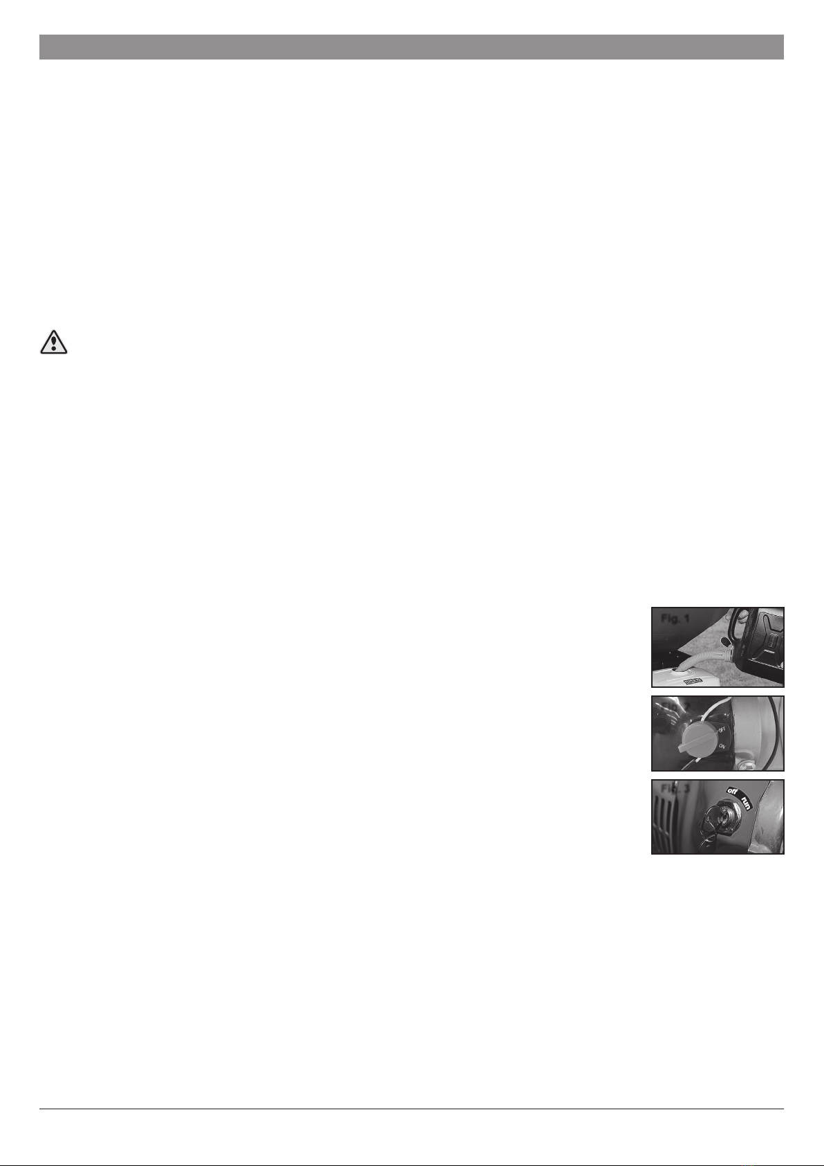
•Thefueltankmustbelledusingafunnel(Fig.1),alwaysintheopenairorinawell-ventilatedspace,with
theengineswitchedoffandhavingcooleddown.Fuelishighlyammable.Donotsmokeorlightare.Use
onlyanapprovedcontainer.Alwaysreplaceandsecurelytightenthefuelcapafterrelling.
• If fuel is spilled, do not attempt to start the engine, but move the machine away from the area of spillage
before starting. Always clean up spilled fuel.
• Place the machine in such a way that the exhaust fumes are blown away from the operator position. If
needed move the machine.
• Do not operate the machine on a paved or gravel surface where ejected material could cause injury.
•Onlyoperatethemachineinanopenspace(e.g.notclosetoawallorotherxedobject).
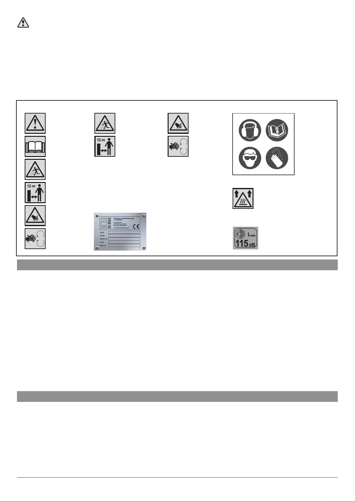
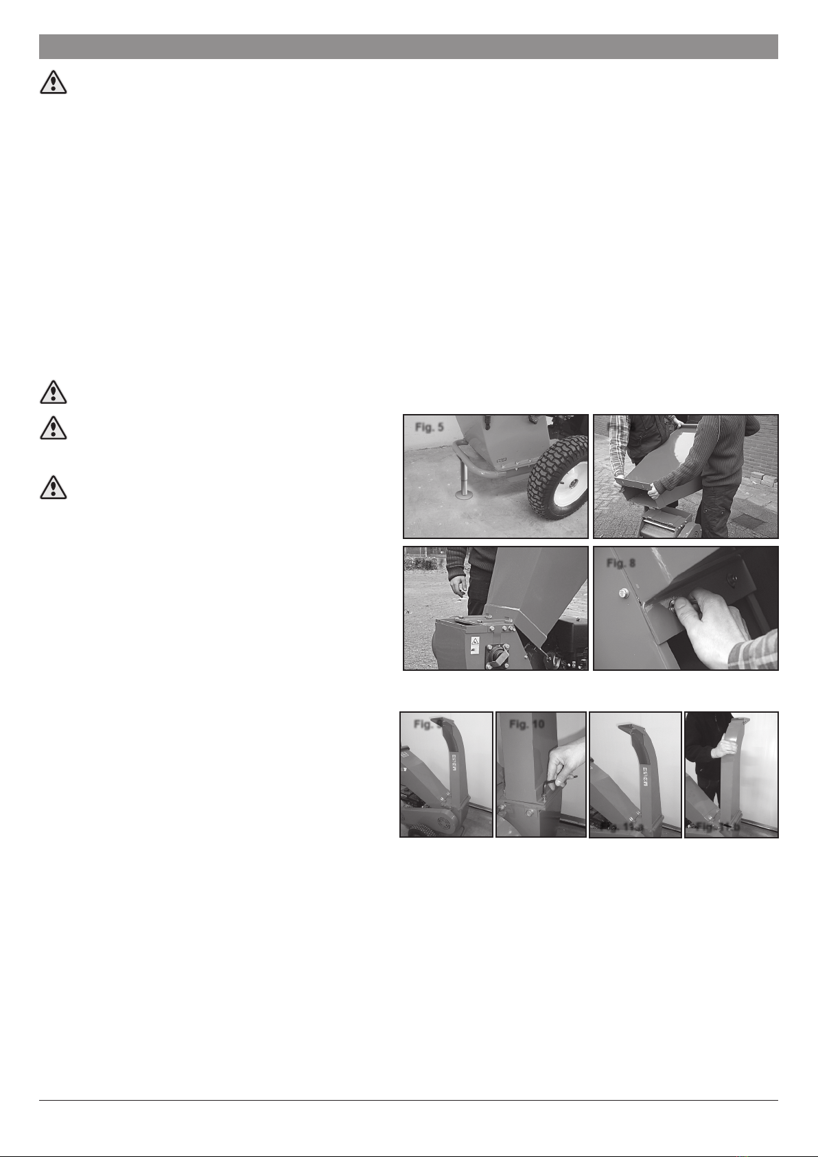
• Never leave the machine unattended. If you leave the machine, stop the engine (Fig. 2) and (if applicable)
remove the key (Fig. 3) from the contact or disconnect the spark plug wire.
• Assemble the machine completely before use. Never use the machine without the infeed or outfeed tube mounted on the machine.
If the machine is equipped with a turnable output tube, never remove the turnable output. Always assemble the belt cover and the
handle. All these parts assure that it is possible to work on a safe and easy way with the machine.
•
If the blades hit a foreign object (anything except wood), or if the machine starts making unusual noises and/or shaking unusually, you
must switch off the machine at once to stop the blades rotating. Switch off the engine and take the machine to the recommended dealer.
• The blades are blunt when the material isn’t smoothly pulled into the machine anymore. The blades should be turned, grinded or
replaced. Blunt blades increase the force on the rotor exponential and can cause broken parts which are not covered by warranty.
•
Keep your face and body as far as possible from the input tube. While feeding the machine do not stand higher than the bottom of the
wheels. Keep your balance and make sure your feet have grip on the soil. Do not bent forwards. Do not allow hands or any other part of
thebodyorclothinginsidetheinfeedoroutfeedtube.Stayawayfrommovingparts.Replacewarningsignsifdamagedornotsufciently
legible.
• It is prohibited to feed any other material into the machine (e.g. metal, stones, plastics or any other material) than those mentioned in the manual.
• If the machine becomes clogged at the input or output tube, shut-off the engine and disconnect the spark plug wire or remove the key
(if applicable) before cleaning the debris. Keep the power source clear of debris and other accumulations to prevent damage to the
engineorpossiblere.Rememberthatoperatingthestartingmechanismontheenginewillcausethecuttingmeanstomove.
• Do not tilt the machine while the engine is running.
Fig. 1
Fig. 3
Fig. 2

5
www.vilagrancha.com
Manual
GTS-1000MZ - EN -
D09-GV09020-01
1.3 Safety directions for use and maintenance
Do not leave the key (when applicable) in the ignition. Never leave the keys unattended. Keep out of reach of children and unautho-
rised persons. Disconnect the spark plug wire before attempting to do maintenance on the machine.
Wait until the engine is cooled down before attempting maintenance on the machine.
During servicing disconnect the battery, if applicable.
The blades have to be sharp and well balanced.
Never repair bent or damaged blades, but replace them. Always use ORIGINAL blades for your own safety!
Do not use, nor perform maintenance in the absence of light.
Remember that operating the starting mechanism on engine powers machines will still cause the cutting means to move.
1.4 Explanation of the stickers and safety symbols (Fig. 4)
2. Description and technical service
2.1 Type description
EachGTS1000MZwoodchipperisprovidedwithafactoryidenticationandserialnumberplatewiththemostimportantdates.Youcan
ndthisplateonthechassisbetweenmotorandrotorhousing.
2.2 Service
This manual contains the instructions for the operation and basic maintenance of the GTS woodchipper. An authorized service dealer
should carry out all other adjustments. It is advised to have the machine serviced once every year by an authorized service dealer.
2.3 Spare parts
Always use ORIGINAL spare parts, which are safe and guaranteed replacements.
2.4 Warranty
The warranty will be granted in accordance with the text on the last page of this instruction manual.
3. General description
The GTS1000MZ is a woodchipper intended to shred all kinds of fresh cut wood with a diameter of maximum 8 cm. It is also possible to
shred roots, but the roots need to be cleaned from sand, earth, rocks or any other materials.
The machine consist out of an engine that propels a rotor using two belts. On the rotor there are two blades installed. Via an infeed
tube the cut wood is introduced into the rotor where the material is shredded. The shredded material is then discharged via the output
tube. An optional turnable output can be installed and allows to change the direction of the output.
On the rotorhousing one counter blade is installed.
132 kg
2013
GTS 900
132 kg
2013
GTS 900
132 kg
2013
GTS 900
132 kg
2013
GTS 900
132 kg
2013
GTS 900
132 kg
2013
GTS 900
132 kg
2013
GTS 900
132 kg
2013
GTS 900
132 kg
2013
GTS 900
132 kg
2013
GTS 900
C
M
Y
CM
MY
CY
CMY
K
D.05.WARNHOT-02_Warning_hot-surface - 38x38mm_BW.pdf 1 8-6-2016 11:35:16
Watch out:
danger!
Sticker 1: Sticker 2:
Sticker 6:
Sticker 7:
Fig. 4
Sticker 5:
Sticker 3: Sticker 4:
Read the
users' manual
carefully
Danger of
yingdebris
Danger of
yingdebris
Keep a
sufcient
distance (12 m)
Keep a
sufcient
distance (12 m)
Serial number
plate
Hotsurface–
Risk of burns
Noise level
Risk of severe
cuts and
wounds
Risk of severe
cuts and
wounds Read the
users’ manual
carefully
Wear safety
goggles, ear
protection and
safety gloves
Risk of
getting stuck
Risk of
getting stuck
Lwa_115dB_40x36mm.pdf 1 20-8-2014 8:45:43

6
Manual
GTS-1000MZ - EN -
D09-GV09020-01
www.vilagrancha.com
4. Unpacking and assembly
An unpacking instruction is available inside the crate. Follow the instructions carefully to prevent damage during unpacking.
4.1 Parts inside the crate
The crate contains the following items:
• Hopper (input tube).
• Discharge tube (output or conveyor).
• Handle.
• Machine (chassis, motor and rotorhouse).
• Manual and unpacking instructions.
• Bag with tools (wrench for starter plug & screw driver) and bolts and nuts (4 long allen bolts (M8x25), 2 short allen bolts (M8x16), 4
rings, 2 wingnuts, and 2 bolts with handle).
• Key for de-blocking the rotor.
4.2 Assembly instructions
The following tools are needed during assembly: Allenwrench 6
4.2.1. Assembly of the hopper (input tube)
The hopper (input tube) is big and heavy. We suggest to never lift it alone.
When mounting the hopper on the machine, the machine
can get out of balance. Support the bumper on the chas-
sis to prevent the machine from tilting (Fig. 5)
Alwaysmountthehopper(inputtube)rst.Itisnot
possible to mount the hopper when the discharge tube
(output) is installed on the machine.
Putthehopperontheoorinfrontofthemachine.Makesure
the hinges are on the bottom, facing the machine. (Fig. 6)
Lift the hopper and hold it above the rotor housing. Slide the
hinges in the holes on the rotor housing.
Tilt the hopper to the front until it touches the rotor housing.
(Fig. 7). Use the 2 long allen bolts (M8x25), 2 spring washers
andtworingstoxthehoppertotherotorhousing.
Tightenrmly.(Fig. 8)
Advice: Put the spring washers over the bolt before putting the
rings.
4.2.2. Assembly of the output tube
Put the output tube on top of the output hole of the rotor
housing (Fig 9). Take the 2 long allen bolts (M8x25) and 2 short
allenbolts(M8x16),and4springwasherstoxtheoutputtube
to the rotorhousing (Fig. 10). The long allen bolts are used on
the back of the machine, the short allen bolts are used on the
front side of the output tube (facing the input tube). Tighten
rmly.
It doesn’t matter how you orientate the output tube. This is a user decision. Both directions are possible. This allows the user to choose
the output direction (Fig 11a and Fig 11b).
4.2.3. Assembly of the handle
Assemblethehandleonthechassis.Putthelongboltswithhandlethroughthechassisandthroughthehandle.Tightenrmly.
4.2.4. Assembly of the (optional) turnable output
Please refer to the manual of the turnable output for the proper instructions.
Fig. 5 Fig. 6
Fig. 7 Fig. 8
Fig. 9 Fig. 10
Fig. 11.a Fig. 11.b

7
www.vilagrancha.com
Manual
GTS-1000MZ - EN -
D09-GV09020-01
5. Controls (Fig 12, 13)
a. Start handle
b. Throttle handle
c. Choke handle
d. Fuel valve
e. On/Off switch
f. Emergency button
g. Deector
h. Input tube, hopper
6. Instructions for use
6.1. Preparation
Check that the machine is assembled according to the assembly instructions. Check following points before using the machine:
• No damage to the machine.
• Allboltsandnutstightenedrmly.
• Oil level of the engine.
Always respect the safety and environment instructions!
Before starting the machine, always check that there are no woodchips in the rotor. These chips can block the rotor, making it
impossible to start the engine.
6.2. Starting the engine
Before starting the engine, execute following steps:
• Open the fuel valve.
• Close the choke handle.
• Open the throttle valve for 1/3.
• Verify that the emergency button is not active (see chapter 6.5).
• Verifythepositionofthedeector(seechapter6.6).
• Put the on/off switch in the “on” position (not applicable for electric start machines).
Pull the starter rope (depending 3 to 6 times) to start the engine.
When the engine is running, push the choke handle back to the normal position. If you leave the choke handle open too long, you will
drawn the engine.
Let the engine run idle for at least 30 seconds before opening the throttle handle.
The machine is now ready for use.
Always start the machine idle (without load). Make sure that the input tube is empty and that there are no woodchips in the rotor.
6.3. Chipping/shredding
Put the branches in the input tube until the woodchipper starts pulling the branches into the machine. Release the branches.
When shredding branches with a big diameter, don’t put too much branches at once. Make sure the speed of the engine doesn’t drop.
Cut side branches thicker than 3cm off from the main branch and gradually feed them into the machine separately.
Fig. 13
h
f
Fig. 12
a
e
b
c
g
d

8
Manual
GTS-1000MZ - EN -
D09-GV09020-01
www.vilagrancha.com
Advice: The hardness of the wood depends on the wood type, the time between pruning and chipping and how dry the branches are.
The machine performs best if the branches are chipped right after pruning.
Check the torque of the blade bolts every two hours. If needed adjust the torque! (see chapter 7.5)
6.4. Stopping the machine
Make sure the machine is completely empty before stopping the engine. After feeding the last branch into the
machine, let the machine turn for a couple of minutes. Then you can switch the machine off using the on/off
switch.
Don’t hesitate to use the emergency button in case of unexpected situations.
6.5. Emergency stop button
The emergency stop button is located on the chassis on the side of the input (Fig 14). The button can be opera-
ted by foot or hand. Push the emergency stop button by pressing the button. The engine will stop immediately.
To release the emergency stop button, turn the red button. Within half a turn, the button is released and it will be possible to start the
machine again.
6.6.Deector
Thedeectorguidesthewoodchipssotheyenduponapredenedplace.Theangleofthedeectorcanbechangedbythewingnut.
Never stand in front of the output of a woodchipper when the engine is turning.
6.7. Blocking of the rotor
It is possible that the rotor blocks because the rotor was not empty before stopping the engine, or the emergency push button was pressed
(leaving woodchips inside the rotor) or because the engine has stopped due to overloading the chipper with too many branches, etc.
To de-block the motor, follow these steps:
Put the on/off switch in the “off” position. Remove the input and output
tubes. Remove the bracket from the bearing housing by loosening the
two bolts. The black cover can now be removed (Fig.15.1). Use the
supplied key and slide it over the shaft of the rotor (Fig.15.2). Twist the
key up and down and remove the woodchips between the blades on
the rotor and the counter blade.
Use a branch or a tool to remove the woodchips between the
blades. Never use your hands. Be careful! The blades are very
sharp and can cause serious injuries. Assemble the input as explained in chapter 4.2.1. Assemble the output as explained in
chapter 4.2.2.
Always check the blades after a jam. Replace the blades immediately when damaged.
Using damaged blades is very dangerous.
6.8. Blocking of output
When too much wet material is put into the input, it is possible that the output jams.
To empty the output tube, follow these steps:
Put the on/off switch in the “off” position. Disassemble the output tube from the machine and remove all the material inside the output
tube. Remove all the material on top of the rotor. Also remove the material inside the rotor to prevent the machine from blocking during
start up.
Use a branch or a tool to remove the woodchips between the blades. Never use your hands. Be careful! The blades are very
sharp and can cause serious injuries.
Assemble the output as explained in chapter 4.2.2.
6.9 Moving the machine
Themachineisequippedwithabumper.Putthemachineinavanoronatrailer.Makesurethebumperistouchingaverticalatsurf-
ace. Now use straps to tie down the machine. Use the chassis to attach the straps to the machine. Check that the machine can’t move.
Never use the input or output tube to strap the machine down.
Fig. 14
Fig. 15.1 Fig. 15.2

9
www.vilagrancha.com
Manual
GTS-1000MZ - EN -
D09-GV09020-01
7. Maintenance
Before you start any maintenance activities, always take following precautions:
• Stop the engine and let the engine cool down.
• Remove the starter plug cap.
• If the machine is equipped with an electrical start system, remove the key from the contact and disconnect the battery.
The GTS1000MZ consists out of parts with a weight over 20kg. Never lift these parts alone. Ask someone to help you lifting
these parts.
• Rotor housing +/- 20kg
• Engine +/- 20kg
7.1. Cleaning
Do not clean the machine with high pressure water.
7.2. Vericationoftheemergencystopbutton
Start the machine as described earlier. Do not put any material in the input (hopper). Push on the emergency button. The machine should stop.
Release the emergency button as described in chapter 6.5. It is now possible to start the machine again. Execute this check before each use.
7.3. Replacing and adjusting the belts
The belts only need to be replaced when they are worn or damaged. Inspect the belts at least 2 times a year.
Unscrew the bolts of the cover of the belt housing (Fig 16.1).
Remove the cover from the belt housing (Fig 16.2).
Un-
screwtheboltsxedhorizontallytotheengine.(Fig.16.3).
Loosenslightlytheboltsthatxtheengineonthechas-
sis (Fig 16.4). Move the engine block in the direction of
the rotor. Now the old belts can be removed and the new
onescanbetted.
Note that once the belts are removed, it is easy to check
the distance between blades and counterblade, because
the rotor can turn freely.
Tension the belts by moving the engine block away from
the rotor and, once the correct belt tension is found,
block the engine position by screwing tight the 4 bolts to
the chassis.
Onceyouhavegottherighttension,checkthatthepulleysarealigned.Youcancheckthisbyholdingabaragainstthepulleys(Fig
16.5).Youhavereachedtherighttensionwhenthebeltcanbepulleddown±6cm/2.5inches(Fig16.6).
Whennewbeltsarettedthedistancebetweenpulleyspindlesshouldbe+/-730mm.Checkagainaftertensioningthebeltsthatthe
pulleys are aligned. Check that all bolts are tightened properly. Put the cover for the belt housing back in place and mount the hopper
and output chute.
After changing the belts, let the machine run for 5 minutes without load. While running without load, check the machine for loose bolts,
unusual noises or vibrations. Now the machine is ready for use.
7.4. Greasing the bearinghousing
There are 2 grease nipples on the machine, on both sides of the rotorhouse,
on the bearinghousings (Fig. 17.1 and Fig. 17.2). Slide a grease pump over the
nippleandllthebearinghousingwithuniversalgrease.
REMARK: if you have problems reaching the grease nipple on the side of the
belt cover, just loosen the bolt that holds the belt cover attached to the rotor
housing. Now you can pull a little on the belt cover and now you should be able
totthegreasepumpoverthenipple.Don’tforgettoputtheboltback!
Grease the bearing housings at least once a year, using universal grease.
Fig. 16.3Fig. 16.1 Fig. 16.2
Fig. 16.4
Fig. 16.5 Fig. 16.6
Fig. 17.1 Fig. 17.2

10
Manual
GTS-1000MZ - EN -
D09-GV09020-01
www.vilagrancha.com
7.5. Replacing the blades
The blades are blunt when the material isn’t pulled into the machine anymore. The blades should be turned, grinded or replaced. The
blades are sharp on both sides, so you can turn the blades around and use the other side of the blade. When this side becomes blunt,
a new pair needs to be installed or the blades can be sharpened.
To replace the blades, follow the steps below:
• Stop engine.
• Turn the engine swith to the "off" position.
• Remove the hopper and output chute.
• Pull the starter rope until you can see the blades trough the input port on the rotorhousing.
• Unscrew the threaded plug M12 on the rotor house, using a screw driver (Fig. 18.1 and 18.2). Insert the rotor locking bolt M12x50
until you feel it's passing under the blade support block (Fig. 18.3). Screw the bolt further in until the bolt head is touching the rotor
house (Fig. 18.4).
• Now the rotor is blocked, it is safe to remove the blade bolts and the blade.
• Unblock the rotor by removing the rotor locking bolt.
Always use gloves when handling the blades.
• Now repeat these steps to remove the second blade.
• In case of turning the blades, clean the blade thoroughly. No dirt should be on the bottom or top side of the blade.
• Clean the surface of the rotor where the blades should be mounted. These surfaces must be spotless.
• Before mounting the blades on the rotor, inspect the blades for damages. Never install damaged blades. In case of damaged
blades and/or doubt, contact your service dealer.
• Before putting the bolts back, add a little Loctite 243 on the side of the bolt.
• Now the blades can be mounted on the rotor. First tighten the bolts
manually, to prevent damaging the thread on the rotor. Than a tool
can be used to tighten the bolts. Don’t forget to block the rotor be-
fore using tools.
• Tighten the bolts with a torque wrench up to 80Nm for the cutting
blades (Fig 19).
• After installing the blades, check the gap between the blades and
the counter blade (Fig. 20).
The gap should not be smaller than 0.5mm and not bigger than
1.00mm. The best way to check the gap is when the counter blade is
in the middle of the grinded surface of the blade.
This adjustment is very critical for the good operation of the machine. If you experience any trouble during this procedure, you
could also remove the belts. In this case the rotor can move freely.
When the distance between the blades is not according the above mentioned distances, the counterblade needs to be adjusted.
Untighten the bolts from the counterblade, do not remove the bolts completely, just untighten them a bit. Adjust the position of the
counterbladeandcheckthedistancebetweentheblades.Whenthegapisaccordingtospecications(0.5-1.00mm),tightenthe
bolts. Check the gap once more. Now put the bolts from the counterblade with a torque wrench up to 50Nm.
Don’t forget to put the caps back on the rotor house.
Don’t forget to re-install the threaded plug back and to fasten it.
When both sides of the blades are blunt, the blades can be sharpened again.
Always ask an experienced technician to sharpen the blades.
Don’t sharpen a damaged blade. Using damaged blades can lead to dangerous situations.
Never use a grinder that doesn’t guarantee a straight sharp edge. Make sure that the cutting edge
during grinding doesn’t become overheated, as this will make the steel soft at the cutting edge.
Whengrinding,respecttheanglesshowningure21.
When the blades have been sharpened again, and they are mounted onto the machine, make sure
the blade bolts don’t touch the counterblade. In case of doubt, replace the blade with a new one.
Fig. 21
Fig. 18.1
Fig. 18.1 Fig. 18.2
Fig. 18.2 Fig. 18.3
Fig. 18.3 Fig. 18.4
Fig. 18.4
Fig. 19 Fig. 20

11
www.vilagrancha.com
Manual
GTS-1000MZ - EN -
D09-GV09020-01
7.6. Replacing motor oil
Please consult the engine manual of the engine manufacturer.
7.7. Engine maintenance
Please consult the engine manual of the engine manufacturer.
8.Technicalspecications
Type GTS1000MZ
Engine YamahaMZ300
Starter Recoil
Displacement 296 cc
Power 10 hp 7,46 kW
Fuel Unleaded
Fuel tank capacity 5,8 l
Oil sensor Yes
Max. diameter branches 80 mm
Input:
Input height 105 cm
Input dimensions 25 x 25 cm
Output:
Output height 138 cm
Output direction Side
Deector 90° adjustable
Emergency stop Yes
Diameter wheels 40 cm
Wheels On ball bearings
Blades 2 + 1 counterblade
Dimensions (l x w x h) 125 x 67 x 138 cm
Weight 132 kg
Measured LWA 111 dB(A)
Guaranteed LWA 115 dB(A)

12
Manual
GTS-1000MZ - EN -
D09-GV09020-01
www.vilagrancha.com
9. Trouble shooting table
Problem Cause Solution
The woodchipper does
not perform properly: the
wood is not pulled in by
the rotor itself.
The chips do not have
the same size.
- The blades are worn too
much.
- The diameter of the branches
inserted into the machine is
too large.
- The gap is too big between
thexedbladeandthe
counter blade: the correct
gap is between 0.5 mm and
1.00 mm.
- Reverse or sharpen or change the blades (chapter 7.5).
- Remove branches thicker than 8.5 cm.
-Adjustthegapbetweenxedbladeandcounterblade:thecorrectgap
is between 0.5 mm and 1.00 mm (see chapter 7.5).
The engine does not
start/ the engine shuts
off by itself.
- Electrical problem with the
engine.
- No fuel.
- No or not enough oil in the
engine (the oil should be level
withthethreadsoftheller
hole).
- Check that the start-switch on the engine is on “on” or “1”.
- Check if the emergency switch is de-activated.
- Check oil and fuel levels.
If necessary: contact your dealer.
The machine jams
during use. The engine
will not start/turn
because the rotor is
jammed.
- The diameter of the branch is
too big.
- There are unacceptable mate-
rials such as stones or metal
in the input tube.
Shut off the engine and remove the key from the start switch. Remove
the cap from the rotor-axle. Turn the rotor a few degrees counter-clock-
wise by means of the de-blocking tool. Block the rotor by blocking this
tool on the rotor axle behind the wheel axle. Remove material from the
input tube by means of a stick or tool and start the machine again. If
necesarry, change the blades.
NEVERPUTYOURHANDINTOTHEINPUTTUBEORROTOR.
The machine does not
throw out chips any
more. The output tube is
jammed.
Too much wet material (leaves,
grass, rotten material) has been
fed into the machine.
Shut off the engine, remove the spark plug cap. Block the rotor-axle by
blocking the special spanner behind the wheel axle. Dismount/remove
the output tube. Do not touch the blades, even if you are wearing
gloves! There is a high risk of cutting your hands badly. Remove
debris with a stick or tool. Mount the output tube again, tighten the
screwsrmly.Removethespecialspannerfromtheaxle.Fitthecapon
the rotor axle. Start the engine again.

13
www.vilagrancha.com
Manual
GTS-1000MZ - EN -
D09-GV09020-01
10. Warranty conditions
1. Warranty
Youareentitledtowarrantyonfactory-andcomponentfaultsprovidedthatthemachineisusedasdescribedinthemanual.Notin-
cluded are parts that are subject to wear. For the engine you should apply to the manufacturer in question.
2. Terms
For professional use: 6 months.
For private use: 2 years.
3. Conditions
The warranty covers the replacement of faulty parts and the corresponding labour, but not the costs of transport. The purchase invoice
isalsothewarrantycerticateandsotheserialnumbermustbementionedontheinvoice.
4. Exceptions
The warranty is invalidated when the operating and maintenance instructions, which are provided with the machine, have not been
followed,whenaninproperusehasbeenmade,whennotoriginalsparepartshavebeenusedorwhenunqualiedrepairershave
tampered with the machine.
5. Where
ThequaliedAfter-Sale-Service,forrepairunderwarranty,isavailablefromthedealerfromwhomyouhave
purchased the machine. Ask for an invoice marked “Warranty Repair” for the repair.

14
Manual
GTS-1000MZ - EN -
D09-GV09020-01
www.vilagrancha.com
12. EC - Declaration of conformity
Declaration according to Annex II.1.A of the Machinery Directive 2006/42/EC
Thislanguageversionofthedeclarationisveriedbythemanufacturer(originaldeclaration).
We:
Business name : Technische Handelmaatschappij J. De Wild B.V.
Adress : De Meeten 54, 4706 NH ROOSENDAAL
Country : NEDERLAND
Declare for the product described below:
Generic denomination : Woodchipper
Commercial name : GTS1000MZ
Type : GTS1000MZ
Serialno. : ______________________
Year : 2016
Function : Woodchipper GTS1000MZ designed to shred fresh wood.
Max. average diameter branches: 80 mm.
Power : YamahaMZ300BARAO,10hp/3600rpm.
Weight : 132 kg.
ThatalltherelevantprovisionsoftheMachineryDirectivearefullled.
That the product also complies with the following European Directives:
- 2006/42/EC Machine Directive
- 2004/108/EC Directive 2004/108/EC of the European Parliament and of the Council of 15 December 2004
on the approximation of the laws of the Member States relating to electromagnetic compati-
bility and repealing Directive 89/336/EEC
- 2000/14/EC Directive 2000/14/EC of the European Parliament and of the Council of 8 May 2000 on the
approximation of the laws of the Member States relating to the noise emission in the environ-
ment by equipment for use outdoors
That the following harmonized standards have been used:
- EN 12100 Safety of Machinery
- EN 13683+A2 Garden Equipment (expect part 5.2.2, 5.2.3.1)
- EN 13525 Forestry Machinery (only part 4.3.4, 4.5.1)
- EN 11201 Acoustics–NoiseemittedbyMachineryandEquipment
- EN 3744 Acoustics–Determinationofsoundpowerlevelsofnoicesources
- EN 55012 Vehicles–Boatsandinternalcombustionengines–RadiodisturbanceCharacteristics
The conformity assessment was carried out by:
Business name :
STÀTNÍZKUŠEBNAZEMĚDĚLSKÝCHPOTRAVINÁŘSKÝCHALESNICKÝCHSTROJŮA.S.
Adress :
Třanovského622/11,16304PRAHA6,CZECHREPUBLIC
NotiedBodynumber : 1016
Examination number : 35-365
Measured Sound Power Level LWA = 111 dB(A)
Guaranteed Sound Power Level LWA = 115 dB(A)
Weighted Sound Pressure Level LpA = 105 dB(A)
ThatthefollowingnaturalorlegalpersonestablishedintheCommunityisauthorizedtocompilethetechnicalle:
Business name : Technische Handelmaatschappij J. De Wild B.V.
Name and position : ing. J.K. Elenbaas, CTO Europe
Adress : De Meeten 54, 4706 NH ROOSENDAAL
Country : NEDERLAND
Done at Roosendaal, 13 June 2016.
Ing. J.K. Elenbaas
CTO Europe


www.vilagrancha.com
Table of contents
Popular Chipper manuals by other brands

Farmi Forest Corporation
Farmi Forest Corporation VALBY CH 260 OPERATION, MAINTENANCE AND SPARE PARTS MANUAL

TruYard
TruYard CM65 Series Safety, operation & maintenance instructions

DK2 Power
DK2 Power OPC506 Assembly guide

Altec
Altec DRM 12 manual

Timberwolf
Timberwolf TW 125PH instruction manual

Hansa
Hansa C40 Operation, maintenance and safety manual