manuals.online logo
Brands
  1. Home
  2. •
  3. Brands
  4. •
  5. Yamaha
  6. •
  7. Musical Instrument
  8. •
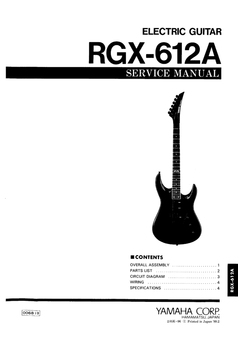
  9. Yamaha Silent Viola SVV-200 User manual

Yamaha Silent Viola SVV-200 User manual

SERVICE MANUAL
HAMAMATSU, JAPAN
0.944K-068 Printed in Japan 2002.05
011635
NV
CONTENTS
SPECIFICATIONS .............................................................................. 3
PANEL LAYOUT.................................................................................. 4
CIRCUIT BOARD LAYOUT................................................................. 6
BLOCK DIAGRAM .............................................................................. 7
DISASSEMBLY PROCEDURE ........................................................... 8
IC BLOCK DIAGRAM.........................................................................11
CIRCUIT BOARDS ............................................................................11
INSPECTIONS.................................................................................. 13
POINTS TO CHECK WHEN NOISE HAS OCCURED ..................... 13
.......................................................................................................... 14
.......................................................................................................... 14
TUNING ............................................................................................ 15
OVERALL CIRCUIT DIAGRAM
PARTS LIST
This document is printed on chlorine free (ECF) paper with soy ink.
SVV-200
20020420-125000
2
SVV-200
WARNING
Components having special characteristics are marked and must be replaced with parts having specification equal to those originally installed.
WARNING: CHEMICAL CONTENT NOTICE!
The solder used in the production of this product contains LEAD. In addition, other electrical / electronic and / or plastic (where
applicable) components may also contain traces of chemicals found by the California Health and WelfareAgency (and possibly other
entities) to cause cancer and / or birth defects or other reproductive harm.
DO NOT PLACE SOLDER, ELECTRICAL / ELECTRONIC OR PLASTIC COMPONENTS IN YOUR MOUTH FOR ANY
REASON WHAT SO EVER!
Avoid prolonged, unprotected contact between solder and your skin! When soldering, do not inhale solder fumes or expose eyes to
solder / flux vapor!
If you come in contact with solder or components located inside the enclosure of this product, wash your hands before handling food.
IMPORTANT NOTICE
This manual has been provided for the use of authorized Yamaha Retailers and their service personnel. It has been assumed
that basic service procedures inherent to the industry, and more specifically Yamaha Products, are already known and under-
stood by the users, and have therefore not been restated.
WARNING: Failure to follow appropriate service and safety procedures when servicing this product may result in
personal injury, destruction of expensive components and failure of the product to perform as speci-
fied. For these reasons, we advise all Yamaha product owners that all service required should be
performed by an authorized Yamaha Retailer or the appointed service representative.
IMPORTANT:
This presentation or sale of this manual to any individual or firm does not constitute authorization, certifica-
tion, recognition of any applicable technical capabilities, or establish a principal-agent relationship of any
form.
The data provided is believed to be accurate and applicable to the unit(s) indicated on the cover. The research engineering,
and service departments of Yamaha are continually striving to improve Yamaha products. Modifications are, therefore, inevi-
table and changes in specification are subject to change without notice or obligation to retrofit. Should any discrepancy
appear to exist, please contact the distributor's Service Division.
WARNING:
Static discharges can destroy expensive components. Discharge any static electricity your body may have
accumulated by grounding yourself to the ground bus in the unit (heavy gauge black wires connect to this bus).
IMPORTANT: Turn the unit OFF during disassembly and parts replacement. Recheck all work before you apply power
to the unit.
3
SVV-200
SPECIFICATIONS
Neck ......................................... Hard Maple
Body ......................................... Spruce
Fingerboard/Tuning Pegs......... Ebony
Bridge....................................... Hard Maple (Aubert)
Frame....................................... Plywood
Chin Rest/Tailpiece .................. Ebony
Adjuster .................................... 1st string (Wittner)
Strings ...................................... Ball-end type (Dominant)
Sensor...................................... Stereo Piezo pick-up (underneath the bridge)
Connectors/Controls ................ • Headphone Output
• EQ CTRL (Equalizer Control)
• LINE OUT
• VOLUME
• EQ MODE Switch (EQ MODE 1/EQ MODE 2)
• POWER Switch (ON/OFF)
Power ....................................... 6F22 (S-006P) 9V battery x1
Battery Life (Continuous Use) .. Using Manganese battery : approximately 5 hours
Using Alkaline battery : approximately 12 hours
String Length............................ 375 mm (14-3/4”)
Body Length ............................. 406 mm (16”)
Output Impedance.................... 1kΩ(LINE OUT)
Dimensions .............................. 677 (L) x 246 (W) x 129 (H) mm
27-5/8” (L) x 9-11/16” (W) x 5-1/16” (H)
Weight (with battery) ................ approximately 740g (1 lbs. 10 oz.)
4
SVV-200
PANEL LAYOUT
FRONT
Tuning peg
Nut
Neck
Fingerboard
4th string (C) 2nd string (D)
3rd string (G) 1st string (A)
Frame
Body
Bridge
Bridge seat
Adjuster
Tailpiece
Chin rest
End pin
Tailpiece Wire
5
SVV-200
CONTROL PANEL side
q
w
e
r
qPOWER Switch
wVOLUME
eEQ CTRL (Equalizer Control)
rEQ MODE Switch
• EQ MODE 1
• EQ MODE 2
y
u
t
tPickup Balancer (located inside)
yLINE OUT jack: Standard phone type
uPHONES jack: Stereo mini type
iBattery Case: 6F22(S-006P) 9V
i
Adjustable Range
Increase the
high sensor
Increase the
low sensor
6
SVV-200
CIRCUIT BOARD LAYOUT
MA MA
JK
PHONE Jack
Battery Box
7
SVV-200
BLOCK DIAGRAM
8
Pickup
Sensor
(Low)
Pickup
Sensor
(High)
Pickup
Assembly
3
55
21
3
3
3
3
2
2
1
1
1
1, 23
12
76
6
24
1
IC1-8P
18
2
7
4
4
4
4
4
6
5
33
67
VOLUME
VR1
SW2
SW1
VR2
EQ CTRL
Pickup
Balancer
TR4
TR1
LD1
TR5
TR3
TR2
+9A
+4.5V
+4.5V
+4.5V
+4.5V
+4.5V
+4.5V
+4.5V
+4.5V
+4.5V
+9A
+4.5V
+4.5V
+9A
+9A
+9A +9A
8
*6
*6
8
+9A
+9A
+5A
+9A
+9A
+9A1
+4.5V
REGULATOR
+5V
GR RE
CN4-3P
CN5-2P
MA JK
CONTROLLED/
DIRECT
POWER ON/OFF
RY1
PHONES
LINE OUT
BATTERY
MJ-074N
JK2
IC3-8P
OP AMP
IC5-8P
OP AMP
IC2-8P
OP AMP
OP AMP
IC1-8P
OP AMP
IC2-8P
OP AMP
IC4-8P
OP AMP
IC5-8P
OP AMP
IC6-4P
IC8-3P
D1
MUTE
IC7-4P
RESET
SUM
SUM
SUM
From IC6
to RY1 1Pin
FT1
FT2
VR3
FT3 H.P.F
CN1-3P
2, 4
2, 4
D2
CN2-5P
CN3-5P
ONOFF
*1
*2
*3
*4
*5
MA Ver-A- MA Ver-B-
IC1, 2 uPC4570G2 NJU7062
IC4 uPC4570G2 LMH6647
*1 PS7113L Not install
*2 Open Short
*3 - Connect IC4-Pin8
(SD: Shutdown)
*4 IC4 Pin1 IC4 Pin6
*5 IC4 Pin8 IC4 Pin7
*6 +9A1 +9A
Only Ver. A
8
SVV-200
DISASSEMBLY PROCEDURE
(Fig. 1) (Fig. 3)(Fig. 2)
[60]
[60]
[80]
[80]
[30]
[30]
(Fig. 4)
PREPARATION
Before disassemble the unit, proceed as follows.
• Turn off the power. (Fig.1)
• Remove the chin rest.
• Remove the battery from the battery box. (Fig.2)
• Remove all the strings and the bridge. (Fig.3)
1. MA Circuit Board (Time required: about 2 min)
1-1 Remove the four (4) screws marked [60] to remove
the cover assembly. (Fig.4)
1-2 Remove the two (2) screws marked [50]. (Fig.5)
1-3 Remove the VR knob marked [60]. The MA circuit
board can then be removed. (Fig.5)
* The shield cover is attached to the circuit
board with adhesive tape, so remove it
carefully.
[30]: Flat Head Screw M2.6x6 MFZN2BL (EC020020)
[60]: Bind Head Tapping Screw-1 3.0x12 MFZN2BL (VB998200)
[80]: Flat Head Tapping Screw-1 3.0x14 MFZN2BL (VC043700)
9
SVV-200
[60]
[50]
COVER ASSEMBLY
MA
(Fig. 5)
2. JK Circuit Board (Time required: about 2 min)
2-1 Remove the three (3) screws marked [80] to
remove the battery plate assembly. (Fig.4)
2-2 Remove the hexagonal nut marked [A]. The JK
circuit board can then be removed. (Fig.6)
* The JK circuit board is attached to the side
board with adhesive tape, so remove it
carefully.
* When removing the JK circuit board, take
care not to lose the two SPACER 1.0. (Fig. 6)
3. HP Jack Assembly (Time required: about 2 min)
3-1 Remove the battery plate assembly.
(See procedure 2-1)
3-2 Remove the nut marked [B]. The HP jack assembly
can then be removed. (Fig.6)
(Fig. 6)
[50]: Bind Head Tapping Screw-P PW 3.0x8 MFZN2BL (V9343100)
[60]: Konb (V2300100)
Nut [A]
Nut [B]
Nut [A]
Nut [B]
Side Board UnitSide Board Unit
SPACER 1.0SPACER 1.0
JK Circuit BoardCircuit Board
HP Jack AssemblyHP Jack Assembly
10
SVV-200
Pic
Pic
kup Assemb
kup Assemb
lyPickup Assembly
Escutcheon
Escutcheon
Escutcheon
[110] [70]
4. Battery Box Assembly
(Time required: about 2 min)
4-1 Remove the battery plate assembly.
(See procedure 2-1)
4-2 Remove the four (4) screws marked [30]. The
battery box assembly can then be removed. (Fig.4)
5. Pickup Assembly (Time required: about 1 min)
5-1 Remove the cover assembly. (See procedure 1-1)
5-2 Push the cable of the pickup assembly into a hole
on the body assembly so that the pickup assembly
floats.
The pickup assembly can then be removed. (Fig.7)
6. Side Board Unit (Time required: about 1 min)
6-1 Remove the screw marked [70] and the two (2)
screws marked [110]. The side board unit can then
be removed. (Fig.8)
(Fig.7)
(Fig. 8)
[70]: Flat Head Tapping Screw-1 3.0X14 MFZN2BL (VC043700)
[110]: Flat Head Tapping Screw-1 3.0X20 MFZN2BL (VH922600)
11
SVV-200
IC BLOCK DIAGRAM
PC4570G2 (XF291A00)
Dual Operational Amplifier
1
2
3
4-V
8
7
6
5
Output A +V
Non-Inverting
Input A
-DC Voltage Supply
+DC Voltage
Supply
Output B
Inverting
Input B
Non-Inverting
Input B
Inverting
Input A
+-
+-
1
2
3
4-V
8
7
6
5
Output A
+V
Non-Inverting
Input A
-DC Voltage Supply
+DC Voltage
Supply
Output B
Inverting
Input B
Non-Inverting
Input B
Inverting
Input A
+-
+-
NJM3414AM(T1) (XR294A00)
Dual Operational Amplifier
MA(Ver. A): IC1, IC2, IC3, IC4
MA(Ver. B): IC3
12
3
4
3
1
4
2
1: V
OUT
2: Manual Reset
3: Vcc
4: GND
PST594C (XT627A00)
SYSTEM RESET
PS7113L-1A (V4494200)
OCMOS FET
123
4
5
6
1
2
3
6
5
4
1: LED ANODE
2: LED CATHODE
3: NC
4: MOS FET Drain
5: MOS FET Source
6: MOS FET Drain
1
2
3
4
7
6
5
8N /C
-IN
+IN
V -
SD
V+
OUTPUT
N /C
+
-
LMH6647MAX (X3124A00)
Operational Amplifier
NJU7062M (X3125A00)
Dual Operational Amplifier
1
2
3
4
7
6
5
8Output 1
IN -1
IN +1
GND
VDD
Output 2
IN -2
IN +2
+
-
+
-
CIRCUIT BOARDS
Note: See parts list for details of
circuit board component parts.
MA: ENA-V883800 2
JK: ENA-V883800 2
•JK Circuit Board
Component Side Pattern Side
Line Out
to Phone Jack Assemblyto Battery
MA(Ver. B): IC4
MA(Ver. B): IC1, IC2 MA(Ver.A): IC6, IC7
MA(Ver. B): IC6, IC7 MA(Ver. A): RY1
MA(Ver. A): IC5
MA(Ver. B): IC5
to MA-CN2 (Ver.A)
to MA-CN2 (Ver.B)
12
SVV-200
Note: See parts list for details of circuit board component parts.
Version A circuit board fast lot only
MA: ENA-V883800 2
JK: ENA-V883800 2
•MA Circuit Board
(Ver. B)
Component Side
Pattern Side
EQ MODE
POWER ON/OFF VOLUME
EQ CTRL
to JK-CN3
to Pickup Sensor
•MA Circuit Board
(Ver. A) EQ MODE POWER ON/OFF VOLUME
EQ CTRL
Pickup Balancer
to JK-CN3
to Pickup Sensor
Component Side
Pattern Side
Pickup Balancer
13
SVV-200
INSPECTION
POINTS TO CHECK WHEN NOISE HAS OCCURED
When a mechanical noise is produced, check and adjust the following points.
1. When the adjusting screw protrudes too much it makes a noise; make
sure the adjuster screw is not too loose.
2. Make sure the adjuster fixing screw is tightened.
3. When the bridge is inclined or touches the escutcheon edge, place the
bridge in the center of the escutcheon and slightly incline it towards
the tailpiece side, so that the bridge is aligned at 90 degrees to the
escutcheon after the strings has been tuned.
1
2
1. Preparation
To check the unit, following jigs are required.
•Stereo Inner phones (Headphones)
•Powered speaker
•Battery (S-006P x 1)
Load a battery into the product.
Connect headphones and a powered speaker to [PHONE] jack and [LINE OUT] jack respectively.
Perform each inspection aurally or visually.
Set each control as follows.
[VOLUME] knob : Minimum
[EQ CTRL] dial : Minimum
[EQ MODE] switch: EQ MODE 2
2. Inspection Procedure
2-1 Power supply and Volume
Turn on the [POWER ON/OFF] switch with the [EQ MODE] switch set to "EQ MODE2", and confirm that the LED
illuminates red.
About 2 seconds after turning on the power, play strings and turn the [VOLUME] knob from minimum to maximum
position, and confirm that the sound volume of headphones or a speaker changes continuously.
Besides, confirm that the no mechanical noise is generated and that the knob can be turned smoothly without interfer-
ence of external fittings.
Next, set the [EQ MODE] switch to "EQ MODE1", and confirm that the LED turns to green.
Finally, confirm that no noise is generated when the [POWER ON/OFF] switch is turned on or turned off.
2-2 Tone Control
Play a string with fingers and turn the [EQ CTRL] dial from minimum to maximum position. And confirm that high
frequencies are gradually emphasized.
Besides, confirm that the no mechanical noise is generated and that the dial can be turned smoothly without interfer-
ence of external fittings.
14
SVV-200
15
SVV-200
TUNING
The Silent Viola is shipped from the factory with the bridge unfitted.
First, set up the bridge and then proceed with tuning.
• The lower side of the bridge supports the 1st string (A), the higher side supports
the 4th string (C). Make sure the bridge is placed properly, then set the bridge in
the bridge seat. (Make sure the logo side of the bridge is facing the tailpiece.)
• Make sure the entire underside of the bridge’s legs is in contact with the pickup.
Also, make sure that the bridge does not slide off of the Bridge Seat or that its
legs are touching the sides of the Bridge Seat. Doing so will result in deterio-
rated sound quality.
• Ensure that the tailpiece side of the bridge stands vertically. If it leans to one
side, use both hands to adjust. Make sure that each string passes over the
corresponding slits in the bridge.
* Playing the viola with a leaning bridge may result in damage to the bridge
or a deterioration in sound quality.
A
D
G
C
1st string
4th string
Looking from the tailpiece
Correct
Bad
Bridge is placed vertically
Bridge seat Tailpiece
Placing the Bridge’s Legs
Bridge seat
Pickup
Bridge Legs (Underside)
Tuning
• The strings are tuned to the following pitches. The 1st string is tuned to A, the
2nd string to D, the 3rd string to G, and the 4th string to C.
Use a piano, tuning fork, tuner, etc., and adjust the pitch of each string using the
tuning pegs. When rotating the peg, apply firm pressure towards the head stock.
• After tuning is complete, make sure that the tailpiece side of the bridge is still
properly aligned. If the bridge is leaning in either direction, slightly loosen the
strings and carefully re-align the bridge using both hands.
• An adjuster is provided on the 1st string for fine tuning the string’s pitch.
Bad
Right angle
Body
SVV-200
SVV-200
SVV-200
ABCDEFGH
1
2
3
4
5
Battery
MA
JK
LINE OUT
PHONE
Power SW
to Pickup Sensor
OP AMP
RESET
REGURATOR +5V
RESET
OP AMP
OP AMP OP AMP
OP AMP
OP AMP
PICKUP
BALANCER
Master Volume
CC11: Not installed
Pickup Volume
(EQ CTRL)
1: COMMON
2: INPUT
3: OUTPUT
NJU7202U50
(X0150A00)
REGULATOR +5V
3
2
1
MA: IC8
1: EMITTER
2: BASE
3: COLLECTOR
2SA1162(O,Y) (VJ927200)
2SC2412K Q,R,S
(VV556400)
2SC3326 A,B (VD303700)
Transistor
MA: TR1, TR2, TR3,
TR4, TR5
1
2
3
1: SOURCE
2: DRAIN
3: GATE
2SK1103-(TX) (VY891400)
FET
MA: FT1, FT2, FT3
1
2
3
1: ANODE(RED)
2: CATHODE
3: ANODE(GREEN)
SPR-39MVW
(VS079300)
LED
MA: LD1
2
2
1
1
3
3
RB160L (VS597600)
Diode
MA: D1
1: ANODE
2: CATHODE
2
1
RE
GR
KEC-54257 0
KEC-54257 0
SVV-200 OVERALL CIRCUIT DIAGRAM (MA -Ver. A-, JK)
Note: See parts list for details of circuit board component parts.
<P.1>
ABCDEFGH
1
2
3
4
5
SVV-200
SVV-200SVV-200
MA
JK
Battery
LINE OUT
PHONE
Power SW
to Pickup Sensor
OP AMP
RESET
REGURATOR +5V
MUTE
OP AMP
OP AMP
OP AMP OP AMP
OP AMP
Pickup Volume
Master Volume
KEC-54257 1
KEC-54257 1
1: COMMON
2: INPUT
3: OUTPUT
NJU7202U50
(X0150A00)
REGULATOR +5V
3
2
1
MA: IC8
1: EMITTER
2: BASE
3: COLLECTOR
2SA1162(O,Y) (VJ927200)
2SC2412K Q,R,S
(VV556400)
2SC3326 A,B (VD303700)
Transistor
MA: TR1, TR2, TR3,
TR4, TR5
1
2
3
1: ANODE(RED)
2: CATHODE
3: ANODE(GREEN)
SPR-39MVW
(VS079300)
LED
MA: LD1
2
2
1
1
3
3
RB160L (VS597600)
Diode
MA: D1
1: ANODE
2: CATHODE
2
1
RE
GR
(EQ CTRL)
PICKUP
BALANCER
1: SOURCE
2: DRAIN
3: GATE
2SK1103-(TX) (VY891400)
FET
MA: FT1, FT2, FT3
1
2
3
SVV-200 OVERALL CIRCUIT DIAGRAM (MA -Ver. B-, JK)
<P.2>
SVV-200
1
PARTS LIST
WARNING
Components having special characteristics are marked and must be replaced with parts having
specifications equal to those originally installed.
CONTENTS
OVERALLASSEMBLY...................................................................................................... 2
ELECTRICAL PARTS ....................................................................................................... 5
• The numbers in “ QTY ” show quantities for each unit.

• The parts with “ - - ” in “ PART NO. ” are not available as spare parts.
• The mark “ } ” in the remarks column indicates that these parts are interchangeable.
• The second letter of the shaded ( ) part number is O, not zero.
• The second letter of the shaded ( ) part number is I, not one.
Note) DESTINATION ABBREVIATIONS
A: Australian model M: South African model
B: British model O: Chinese model
C: Canadian model Q: South-east Asia model
D: German model T: Taiwan model
E: European model U: U.S.A. model
F: French model V: General export model (110V)
H: North European model W: General export model (220V)
I: Indonesian model N,X: General export model
J: Japanese model Y: Export model
SVV-200
SVV-200
2
OVERALL ASSEMBLY
C30
A20
70
80
10
30
90
40
50
60
20
A30
B10
B30
B20
A30a
A30b
F30
F30
F20
F10
H40
H20
H10
F40
F20
A10 A50
D20
D30
D100
A40
D50 D50
D10
D70
D60
A60
A70
C60
C10
C70
G10
G50
G80
G40
G70
G60
G30
G20
C20
C50
C40
E30
E20
E10
D90
A80
D80
D40
C80
C90
C100
C110
SVV-200
3
REF NO.PART NO. DESCRIPTION REMARKS QTY RANK
RANK : Japan only* : N w parts
*
*
*
*
*
*
*
*
*
*
*
*
*
*
*
*
*
*
*
*
*
10
20
30
40
50
60
70
70
80
90
A10
A20
A30
A30a
A30b
A40
A50
A60
A70
A80
B10
B20
B30
C10
C20
C30
C40
C50
C60
C70
C80
C90
C100
C110
D10
D20
D30
D40
D50
D60
D70
D80
D90
D100
E10
E20
E30
F10
F20
F20
F30
F30
F40
G10
--
--
V8771600
--
--
--
--
--
V8772600
V8772200
--
--
--
V8773200
V8773300
--
VB304400
V8773400
V8505600
VB998200
--
VC043700
V8771600
--
--
--
--
--
--
V8774400
--
--
V9065700
VC043700
V8774300
V9394000
V9394100
VH922600
--
V8773700
V8773800
V8773900
V6059100
V4514500
V2300100
V6228200
V8774500
V8774600
V9551400
--
V8774100
V8125300
EC020020
--
--
--
V8775400
--
V8775400
--
V9065700
--
Viola mittel #136
Viola mittel #137
Viola mittel #138
Viola mittel #139
PH- 3P
MA-JK
3.0X12 MFZN2BL
3.0X14 MFZN2BL
V-30 V-60
3.0X16 MFZN2BL
3.0X14 MFZN2BL
3.0X20 MFZN2BL
MA
PW 3.0X8 MFZN2BL
2.6X6 MFZN2BL
A,C
D,G
SVV-200 (V877070)
(V877150)
(V877170)
(V877180)
(V877190)
(V877200)
(V877210)
(V877230)
(V877150)
(V877280)
(V877360)
(V877350)
(V877240)
(V877250)
(V547270)
(V877280)
(V877420)
(V877480)
(V906560)
(V934310)
(V877340)
(V883800)
VOLUME
(V877350)
(V877420)
(V877470)
(V877510)
(V877520)
(V877500)
(V877490)
4
3
2
2
2
2
2
2
4
2
2
01
03
01
01
01
01
04
06
08
01
OVERALLASSEMBLY
Overall Assembly
Sub Assembly(2)
Tailpiece Assembly
String1,A
String2,D
String3,G
String4,C
Bridge
Bridge
Chin Rest
Name Plate
Sub Assembly(2)
Sub Assembly(1)
Pickup Spacer
Pickup Assembly
Pickup
Connector Housing
Cover Assembly
Connector Assembly
Bind Head Tapping Screw-1
Battery Plate Assembly
Flat Head Tapping Screw-1
Tailpiece Assembly
Tailpiece
Adjuster
Tailpiece wire
Sub Assembly(1)
Wooden Unit Assembly
Side Board Spacer
Escutcheon
Washer
Round Head Tapping Screw
Side Board Unit
Flat Head Tapping Screw-1
End Sheet
Body Spacer A
Body Spacer B
Flat Head Tapping Screw-1
Cover Assembly
Cover
Shield Cover
Circuit Board
Switch Sheet
Bind Head Tapping Screw-P
Knob
Rubber Lid
Circuit Board Spacer
Side Board Cushion
Cover Spacer
Battery Plate Assembly
Battery Plate
Battery Box Assembly
Flat Head Screw
Wooden Unit Assembly
Body Assembly
Tuning Peg
Tuning Peg
Tuning Peg
Tuning Peg
Nut
Side Board Unit
Side Board Assembly

Other manuals for Silent Viola SVV-200

1

Other Yamaha Musical Instrument manuals

Yamaha YVN500S User manual

Yamaha

Yamaha YVN500S User manual

Yamaha Clavinova CLP-340 User manual

Yamaha

Yamaha Clavinova CLP-340 User manual

Yamaha Clavinova CLP-115 User manual

Yamaha

Yamaha Clavinova CLP-115 User manual

Yamaha Clavinova CLP-150 Installation and operation manual

Yamaha

Yamaha Clavinova CLP-150 Installation and operation manual

Yamaha Clavinova CLP-725 User manual

Yamaha

Yamaha Clavinova CLP-725 User manual

Yamaha Electone B-40 User manual

Yamaha

Yamaha Electone B-40 User manual

Yamaha VSS-200 User manual

Yamaha

Yamaha VSS-200 User manual

Yamaha YPR-20 User manual

Yamaha

Yamaha YPR-20 User manual

Yamaha Clavinova CLP-152S Assembly instructions

Yamaha

Yamaha Clavinova CLP-152S Assembly instructions

Yamaha DG1590A User manual

Yamaha

Yamaha DG1590A User manual

Yamaha PSR-S710 Instruction Manual

Yamaha

Yamaha PSR-S710 Instruction Manual

Yamaha Electone ME-30BX User manual

Yamaha

Yamaha Electone ME-30BX User manual

Yamaha Silent Series User manual

Yamaha

Yamaha Silent Series User manual

Yamaha Clavinova CLP-115 User guide

Yamaha

Yamaha Clavinova CLP-115 User guide

Yamaha CH-500 User manual

Yamaha

Yamaha CH-500 User manual

Yamaha CP4 Stage Instruction Manual

Yamaha

Yamaha CP4 Stage Instruction Manual

Yamaha KB-180 User manual

Yamaha

Yamaha KB-180 User manual

Yamaha Violin V5SA User manual

Yamaha

Yamaha Violin V5SA User manual

Yamaha Electone FS-50 User manual

Yamaha

Yamaha Electone FS-50 User manual

Yamaha Clavinova CLP-970A User manual

Yamaha

Yamaha Clavinova CLP-970A User manual

Yamaha Electone B-20R User manual

Yamaha

Yamaha Electone B-20R User manual

Yamaha Clavinova CVP-25 User manual

Yamaha

Yamaha Clavinova CVP-25 User manual

Yamaha Clavinova CLP-950 User manual

Yamaha

Yamaha Clavinova CLP-950 User manual

Yamaha YCH7018 User manual

Yamaha

Yamaha YCH7018 User manual

Popular Musical Instrument manuals by other brands

Wurlitzer 4100 series Guide

Wurlitzer

Wurlitzer 4100 series Guide

Roland RD-64 owner's manual

Roland

Roland RD-64 owner's manual

Johannus WM-47 quick start guide

Johannus

Johannus WM-47 quick start guide

K&K Sound pure classic user manual

K&K Sound

K&K Sound pure classic user manual

Roland KR-11 owner's manual

Roland

Roland KR-11 owner's manual

Roland RG-3M Brochure & specs

Roland

Roland RG-3M Brochure & specs

impact Firenza manual

impact

impact Firenza manual

Roland FP-3 owner's manual

Roland

Roland FP-3 owner's manual

thomann Harley Benton Electric Cello HBCE 990 user manual

thomann

thomann Harley Benton Electric Cello HBCE 990 user manual

Ibanez AEQ-2TM Information

Ibanez

Ibanez AEQ-2TM Information

Hammond SK Pro Series manual

Hammond

Hammond SK Pro Series manual

Roland Atelier AT-90SL owner's manual

Roland

Roland Atelier AT-90SL owner's manual

Rogers Imagine 351T quick start guide

Rogers

Rogers Imagine 351T quick start guide

Hammond A-405SP owner's manual

Hammond

Hammond A-405SP owner's manual

Roland GP607 owner's manual

Roland

Roland GP607 owner's manual

B.C. Rich Bich 10 Brochure & specs

B.C. Rich

B.C. Rich Bich 10 Brochure & specs

Dynatone DPR-3500 owner's manual

Dynatone

Dynatone DPR-3500 owner's manual

Classenti CDP 2 owner's manual

Classenti

Classenti CDP 2 owner's manual

manuals.online logo
manuals.online logoBrands
  • About & Mission
  • Contact us
  • Privacy Policy
  • Terms and Conditions

Copyright 2025 Manuals.Online. All Rights Reserved.