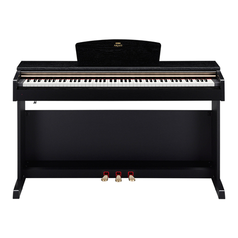
YDP-131/YDP-131C
9
9. End Block Assembly (L, R)
(Time required: About 5 minutes)
9-1 Remove the top board assembly. (See procedure 2)
9-2 Remove the key cover assembly. (See procedure 6)
9-3 Remove the stopper rail assembly. (See procedure 7)
9-4 Remove the rack L. (See procedure 8)
9-5 Remove the screw marked [S10]. (Fig. 7)
9-6 Slide the end block assembly L backward and lift it
out. (Fig. 7)
* The left and right end block assembly can then be
removed in the same manner.
10. Keyboard Assembly
(Time required: About 10 minutes)
10-1 Remove the top board assembly. (See procedure 2)
10-2 Remove the key cover assembly. (See procedure 6)
10-3 Remove the stopper rail assembly. (See procedure 7)
10-4 Remove the rack L and R. (See procedure 8)
10-5 Remove the end block assembly L and R.
(See procedure 9)
10-6 Remove the two (2) screws marked [S03D]. The cable
holder can then be removed. (Fig. 7)
10-7 Remove the nine (9) screws marked [S06] and the eight
(8) screws marked [S07]. The keyboard assembly can
then be removed. (Fig. 7)
9. 拍子木Assy(L・R)(所要時間:約 5 分 )
9-1 屋根Assyを外します。(2項参照)
9-2 スライド蓋Assyを外します。(6項参照)
9-3 鍵盤押えAssyを外します。(7項参照)
9-4 ラック(L)を外します。(8項参照)
9-5 [S10]のネジ1本を外します。(図7)
9-6 拍子木(L)Assyを後方へスライドさせて外します。
(図7)
※ 拍子木(R)Assyも同様に外すことができます。
10. GHL(GHS)鍵盤Assy(所要時間:約10分)
10-1 屋根Assyを外します。(2項参照)
10-2 スライド蓋Assyを外します。(6項参照)
10-3 鍵盤押えAssyを外します。(7項参照)
10-4 ラック(L・R )を外します。(8項参照)
10-5 拍子木Assy(L・R)を外します。(9項参照)
10-6 [S03D]のネジ2本を外し、束線固定金具Assyを外し
ます。(図7)
10-7 [S06]のネジ9本と[S07]のネジ8本を外し、GHL
(GHS)鍵盤Assyを外します。(図7)
11. HP Circuit Board
(Time required: About 6 minutes)
11-1 Remove the top board assembly. (See procedure 2)
11-2 Remove the key cover assembly. (See procedure 6)
11-3 Remove the stopper rail assembly. (See procedure 7)
11-4 Remove the rack L. (See procedure 8)
11-5
Remove the end block assembly L. (See procedure 9)
11-6 Remove the two (2) hexagonal nuts marked [3B]. The
HP circuit board can then be removed. (Fig. 7)
11. HPシート
(所要時間:約 6 分 )
11-1 屋根Assyを外します。(2項参照)
11-2 スライド蓋Assyを外します。(6項参照)
11-3 鍵盤押えAssyを外します。(7項参照)
11-4 ラック(L)を外します。(8項参照)
11-5 拍子木(L)Assyを外します。(9項参照)
11-6 [3B]の特殊ナット2個を外し、HPシートを外します。
(図7)
12.
MV Circuit Board, PN Circuit Board
(Time required: About 7 minutes each)
12-1 Remove the top board assembly. (See procedure 2)
12-2 Remove the key cover assembly. (See procedure 6)
12-3 Remove the stopper rail assembly. (See procedure 7)
12-4 Remove the rack L. (See procedure 8)
12-5 Remove the end block assembly L. (See procedure 9)
12-6 MV Circuit Board
Remove the three (3) screws marked [9A]. The MV
circuit board can then be removed. (Fig. 8)
12-7 PN Circuit Board
Remove the six (6) screws marked [9B].The PN circuit
board can then be removed. (Fig. 8)
12. MVシート、PNシート(所要時間:各約7分)
12-1 屋根Assyを外します。(2項参照)
12-2 スライド蓋Assyを外します。(6項参照)
12-3 鍵盤押えAssyを外します。(7項参照)
12-4 ラック(L)を外します。(8項参照)
12-5 拍子木(L)Assyを外します。(9項参照)
12-6 MVシート
[9A]のネジ3本を外し、MVシートを外します。(図8)
12-7 PNシート
[9B]のネジ6本を外し、PNシートを外します。(図8)
13. SWシート(所要時間:約 7 分 )
13-1 屋根Assyを外します。(2項参照)
13-2 スライド蓋Assyを外します。(6項参照)
13-3 鍵盤押えAssyを外します。(7項参照)
13. SW Circuit Board
(Time required: About 7 minutes)
13-1 Remove the top board assembly. (See procedure 2)
13-2 Remove the key cover assembly. (See procedure 6)
13-3 Remove the stopper rail assembly. (See procedure 7)
