Yamaha RX-V1073 Quick start guide

English
Français
Deutsch
Svenska
Italiano
Español
Nederlands
AV Receiver/Ampli-tuner audio-vidéo
G
Easy Setup Guide
Manuel de configuration rapide
Anleitung zur Schnelleinrichtung
Snabbinstallationsguide
Guida di configurazione rapida
Guía de configuración sencilla
Easy Setup-gids
RX-V1073_esg_G_cover1.fm Page 1 Monday, April 23, 2012 2:03 PM
Black process 45.0° 240.0 LPI

En 1
Check that the following accessories are supplied with the product.
The following cables (not supplied) are required to build the system described in this
document.
• Speaker cables (depending on the number of speakers)
• HDMI cable (x2)
• Audio pin cable (x1)
• Digital optical cable or stereo pin cable (x1*)
* Not required if your TV supports ARC (Audio Return Channel)
1Preparation
Accessories
Remote control Batteries
(AAA, R03, UM-4) (x2)
Insert the batteries the right way round.
AM antenna FM antenna YPAO microphone
Power cable CD-ROM
(Owner’s Manual) Safety Brochure Easy Setup Guide
• The illustrations of the main unit used in this guide are of the Europe model, unless otherwise
specified.
*One of the above is supplied depending
on the region of purchase.
*The supplied power cable
varies depending on the
region of purchase.
Cables required for connections
This document explains how to set up a 5.1- or 7.1-channel system and
play back surround sound from a BD/DVD on the unit.
To reduce the impact on natural resources, the Owner’s Manual for this product is
supplied on CD-ROM. For more information about this product, refer to the
Owner’s Manual on the supplied CD-ROM.
PDF versions of this guide and “Owner’s Manual” can be downloaded from the
following website.
http://download.yamaha.com/
Easy Setup Guide
English
AV Receiver
RX-V1073_esg_C.fm Page 1 Wednesday, April 25, 2012 10:54 AM
Black process 45.0° 240.0 LPI

2En
Set up the speakers in the room using the following diagram as a reference.
For information on other speaker systems, refer to “Owner’s Manual”.
1Front speaker (L)
2Front speaker (R)
3Center speaker
4Surround speaker (L)
5Surround speaker (R)
6Surround back speaker (L)
7Surround back speaker (R)
9Subwoofer
2Placing speakers
5.1-channel system
12
39
45
10° to 30°10° to 30°
7.1-channel system
45
12
39
67
30 cm or more
10° to 30° 10° to 30°
RX-V1073_esg_C.fm Page 2 Wednesday, April 25, 2012 10:54 AM
Black process 45.0° 240.0 LPI

En 3
■Connecting speaker cables
Speaker cables have two wires. One is for connecting the
negative (–) terminals of the unit and the speaker, and the
other is for the positive (+) terminals. If the wires are
colored to prevent confusion, connect the black wire to
the negative and the other wire to the positive terminals.
aRemove approximately 10
mm of insulation from the
ends of the speaker cable
and twist the bare wires of
the cable firmly together.
bLoosen the speaker
terminal.
cInsert the bare wires of the cable into the gap on the side
(upper right or bottom left) of the terminal.
dTighten the terminal.
Using a banana plug
(Canada, China and
Australia models only)
aTighten the speaker
terminal.
bInsert a banana plug into
the end of the terminal.
1Connect the front speakers (1/2)
to the FRONT (//\) terminals. 2Connect the center speaker (3) to the
CENTER terminal.
3Connecting speakers/subwoofer
• Under its default settings, the unit is configured for 8-ohm
speakers. When connecting 6-ohm speakers, set the unit’s
speaker impedance to “6 ΩMIN”. For details, see “Setting the
speaker impedance” in “Owner’s Manual”.
• Use a subwoofer equipped with built-in amplifier.
• Before connecting the speakers, remove the unit’s power cable
from the AC wall outlet and turn off the subwoofer.
• Ensure that the core wires of the speaker cable do not touch
each other or come into contact with the unit’s metal areas. This
may damage the unit or the speakers. If the speaker cables
short circuit, “Check SP Wires” will appear on the front display
when the unit is turned on.
FRONT
-
+
aa
b
d
c
– (black)
+ (red)
FRONT
+
a
b
Banana plug
1
2
ZONE OUT
CENTER
SUBWOOFER
ZONE 2
ROUND SUR. BACK
SPEAKERS
CENTER FRONTSURROUND BACKSURROUND
BI–AMP
ZONE 2/F.PRESENCE/
R L R R R
LL L
SINGLE
PRE OUT
SUBWOOFER
CENTER
FRONT
SURROUND SUR. BACK
(SINGLE)
EXTRA SP
12
3
45
9
The unit (rear)
1
2
ZONE OUT
CENTER
SUBWOOFER
ZONE 2
ROUND SUR. BACK
SPEAKERS
CENTER FRONTSURROUND BACKSURROUND
BI–AMP
ZONE 2/F.PRESENCE/
R L R R R
LL L
SINGLE
PRE OUT
SUBWOOFER
CENTER
FRONT
SURROUND SUR. BACK
(SINGLE)
EXTRA SP
12
3
45
9
The unit (rear)
RX-V1073_esg_C.fm Page 3 Wednesday, April 25, 2012 10:54 AM
Black process 45.0° 240.0 LPI

4En
3Connect the surround speakers
(4/5) to the SURROUND (//\)
terminals.
4Connect the subwoofer (9) to the
SUBWOOFER (1) jack. Connect the surround back speakers
(6/7) to the SURROUND BACK (//\)
terminals.
1
2
ZONE OUT
CENTER
SUBWOOFER
ZONE 2
ROUND SUR. BACK
SPEAKERS
CENTER FRONTSURROUND BACKSURROUND
BI–AMP
ZONE 2/F.PRESENCE/
R L R R R
LL L
SINGLE
PRE OUT
SUBWOOFER
CENTER
FRONT
SURROUND SUR. BACK
(SINGLE)
EXTRA SP
12
3
45
9
The unit (rear)
1
2
ZONE OUT
CENTER
SUBWOOFER
ZONE 2
ROUND SUR. BACK
SPEAKERS
CENTER FRONTSURROUND BACKSURROUND
BI–AMP
ZONE 2/F.PRESENCE/
R L R R R
LL L
SINGLE
PRE OUT
SUBWOOFER
CENTER
FRONT
SURROUND SUR. BACK
(SINGLE)
EXTRA SP
12
3
45
9
Audio pin cable
The unit (rear)
For 7.1-channel system
1
2
ZONE OUT
CENTER
SUBWOOFER
ZONE 2
ROUND SUR. BACK
SPEAKERS
CENTER FRONTSURROUND BACKSURROUND
BI–AMP
ZONE 2/F.PRESENCE/
R L R R R
LL L
SINGLE
PRE OUT
SUBWOOFER
CENTER
FRONT
SURROUND SUR. BACK
(SINGLE)
EXTRA SP
67
12
3
45
9
The unit (rear)
RX-V1073_esg_C.fm Page 4 Wednesday, April 25, 2012 10:54 AM
Black process 45.0° 240.0 LPI

En 5
4Connecting external devices
INPUT
MAIN ZONE
VOLUME
PURE DIRECT
NETWORKDC OUT
5V
0.5A
( 3 NET )
MONITOR OUT/
ZONE OUT
HDMI OUT
ARC
12
HDMI
(1 BD/DVD)
AV 1 AV 2 AV 3 AV 4 AV 5 AV 6 AV 7
TRIGGER
OUT
1
2
RS-232C
YPBPR
YPBPR
YPBPR
MONITOR OUT/ZONE OUT
IN OUT
AV 1
AV 3
REMOTE
COMPONENT VIDEO
A
AV 2
B
C
AV 4 D
AV OUT
R
L
AV 3 AV 4AV 2AV 1
(1 BD/DVD)
OPTICAL
4
OPTICAL
3
COAXIAL
2
COAXIAL
1
PHONO
GND
AC IN
OPTICAL
1
2
AUDIO 4
MULTI CH INPUT ZONE OUT
AUDIO 3AUDIO 2AUDIO 1
(2 TV)
CENTER
SUBWOOFER
ZONE 2FRONT
SURROUND SUR. BACK
SPEAKERS
CENTER FRONTSURROUND BACKSURROUND
BI–AMP
ZONE 2/F.PRESENCE/
R
5
COAXIAL
6
L R R R
LL L
SINGLE
PRE OUT
SUBWOOFER
CENTER
FRONT
SURROUND SUR. BACK
(SINGLE)
EXTRA SP
12V 0.1A
FM 75Ω
ANTENNA
AM
(4 RADIO)
(1 BD/DVD)
AV 1
HDMI OUT
ARC
12
HDMI HDMI
OPTICAL
L
R
OPTICAL
AUDIO 1
(2 TV)
5
L
R
L
R
O
O
HDMI
HDMI
HDMI
a
d
c
HDMI
b
TVAudio out (digital optical or
analog stereo) HDMI in HDMI out
BD/DVD player
HDMI OUT 1
jack
HDMI (AV 1) jack
AUDIO 1
(OPTICAL or AUDIO) jack
The unit (rear)
To an AC wall
outlet
Turn on the unit
The unit (front)
Press the bottom of the
front panel door gently to open the door
1Connect external devices to the unit.
aConnect a BD/DVD player to the unit with an HDMI
cable.
If the BD/DVD player is currently connected to the
TV directly with an HDMI cable, disconnect the
cable from the TV and connect it to the unit.
bConnect a TV to the unit with the other HDMI cable.
cConnect a TV to the unit with a digital optical cable
or a stereo pin cable.
This connection is required to play back TV audio
on the unit. This connection is not required if your
TV supports ARC (Audio Return Channel).
dConnect the supplied power cable to the unit and
then to an AC wall outlet.
• For information on how to connect radio antennas or other
external devices, see “PREPARATIONS” in “Owner’s Manual”.
2Turn on the unit, the TV and the BD/DVD
player.
3Use the TV remote control to change the
TV input to video from the unit.
The connections are complete. Proceed to the next
page to optimize the speaker settings.
• By connecting a TV to the unit with an HDMI cable, you can
configure the unit’s settings with the menu displayed on the TV. In
addition, you can select the on-screen menu language from English
(default), Japanese, French, German, Spanish, Russian and
Chinese. For details, refer to “Owner’s Manual”. In this guide,
illustrations of English menu screens are used as examples.
RX-V1073_esg_C.fm Page 5 Wednesday, April 25, 2012 10:54 AM
Black process 45.0° 240.0 LPI

6En
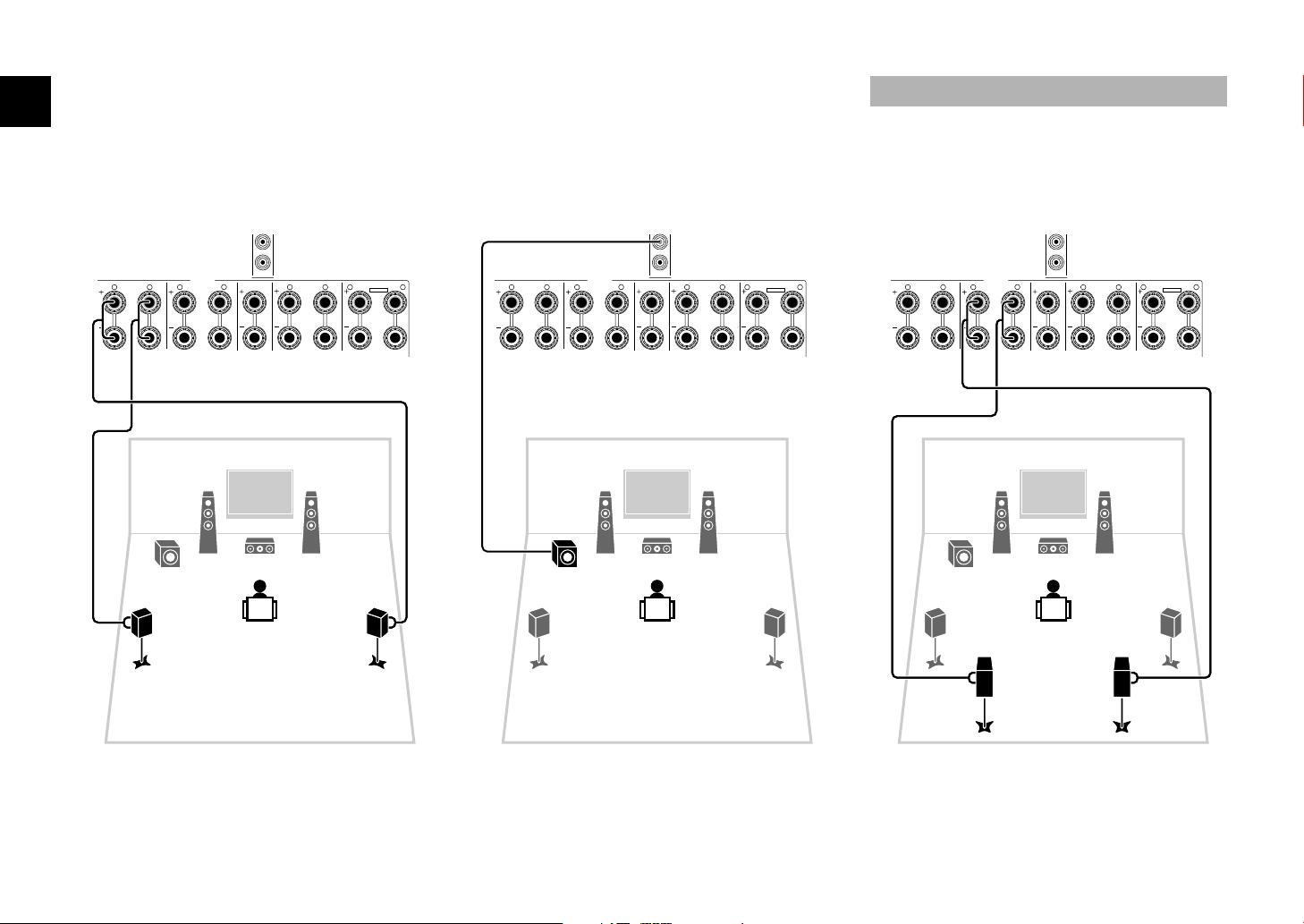
The Yamaha Parametric room Acoustic Optimizer (YPAO) function detects speaker connections, measures the
distances from them to your listening position(s), and then automatically optimizes the speaker settings, such as
volume balance and acoustic parameters, to suit your room.
Preparing for YPAO
5
Optimizing the speaker settings automatically (YPAO)
TV VOL TV CH
TV
INPUT
MUTE
CODE SET
90
10
ENT
MEMORY
5687
1234
MOVIE
ENHANCER
TUNING PRESET
BAND
DISPLAYRETURN
ENTER
ON
SCREEN OPTION
TOP MENU
MUTE
PROGRAM VOLUME
POP-UP/MENU
PURE DIRECT
STRAIGHT
INFO SLEEP
MUSIC
PARTY HDMI OUT
TUNER
MAIN
ZONE 2
MODE
SCENE
4321
TVBD/DVD
NET
RADIO
SOURCE
RECEIVER
AV
AUDIO
5 6 7
V-AUX
1234
1234
SUR. DECODE
PHONO MULTI
USB NET
T
V VOL
T
V C
H
TV
INPU
T
MUTE
CO
DE
S
E
T
9
0
1
0
E
N
T
MEMOR
Y
5
6
8
1
2
3
4
MOVI
E
ENHAN
C
E
R
TU
NIN
G
PRE
S
E
T
BAND
D
ISPLAY
O
N
SC
REEN OPTIO
N
T
O
P MEN
U
MUTE
PR
OG
RAM V
O
L
U
M
E
PO
P-
U
P
/
MEN
U
PU
RE DIRE
C
T
S
TRAI
GH
T
INF
O
S
LEEP
M
USI
C
PARTY
H
DMI
OU
T
TUNER
MAIN
Z
O
NE
2
M
OD
E
S
CEN
E
4
3
2
1
TV
B
D
/
DV
D
NE
T
RAD
I
O
SOU
R
CE
RE
C
EIVER
AV
A
UDI
O
5
6
7
V
-
AUX
1
2
3
4
1
2
3
4
SU
R. DE
CO
D
E
P
HONO MULT
I
U
S
B
N
ET
Cursor keys
ENTER
RETURN
• During the measuring process, test tones are output at high volume. Ensure that the test
tones do not frighten small children. Also, refrain from using this function at night when it
may be a nuisance to others.
• During the measuring process, you cannot adjust the volume.
• During the measuring process, keep the room as quiet as possible.
• Do not connect headphones.
• Do not stand between the speakers and the YPAO microphone during the measurement
process (about 3 minutes).
• Move to the corner of the room or leave the room.
YPAO MIC
VOLUME HIGH CUT
CROSSOVER/
MIN MAXMIN MAX
The unit (front)
Place the YPAO microphone at your
listening position (same height as your
ears). We recommend the use of a
tripod as a microphone stand. You can
use the tripod screws to fix the
microphone in place.
YPAO
microphone
Ear height
Turn on the subwoofer and set
the volume to half. If the
cross-over frequency is
adjustable, set it to maximum.
1Connect the YPAO microphone to the
YPAO MIC jack on the front panel.
The following screen appears on the TV.
• To cancel the operation, disconnect the YPAO microphone
before starting the measurement.
2To start the measurement, use the cursor
keys to select “Measure” and press
ENTER.
The measurement will start in 10 seconds.
The following screen appears on the TV when
the measurement finishes.
• If any error message (such as E-1) or warning message (such
as W-2) appears, see “Error messages” or “Warning
messages” in “Owner’s Manual”.
• If the warning message “W-1:Out of Phase” appears, see
“If “W-1:Out of Phase” appears” (next page).
RX-V1073_esg_C.fm Page 6 Wednesday, April 25, 2012 10:54 AM
Black process 45.0° 240.0 LPI

En 7
3Use the cursor keys to select
“Save/Cancel” and press ENTER.
4Use the cursor keys to select “SAVE” and
press ENTER.
5Disconnect the YPAO microphone from the
unit.
This completes optimization of the speaker settings.
Follow the procedure below to check the speaker
connections.
Depending on the type of speakers or room
environment, this message may appear even if the
speakers are connected correctly.
aUse the cursor keys to select “Result” and press ENTER.
bUse the cursor keys to select “Wiring”.
cCheck the cable connections (+/–) of the speaker that
was identified as being “Reverse” in the warning
message.
If the speaker is connected correctly:
You can save the current settings.
Press RETURN and proceed to step 3.
If the speaker is connected incorrectly:
Turn off the unit, reconnect the speaker cable, and then
try YPAO measurement again.
• The YPAO microphone is sensitive to heat, so should not be
placed anywhere where it could be exposed to direct sunlight or
high temperatures (such as on top of AV equipment).
If “W-1:Out of Phase” appears
RX-V1073_esg_C.fm Page 7 Wednesday, April 25, 2012 10:54 AM
Black process 45.0° 240.0 LPI

8En
Now let’s play back a BD/DVD.
We recommend playing back multichannel audio
(5.1-channel or more) to feel surround sound produced
by the unit.
1Press AV 1 to select “AV 1” as the input
source.
2Start playback on the BD/DVD player.
3Press STRAIGHT repeatedly to select
“STRAIGHT”.
4Press VOLUME to adjust the volume.
This completes the basic setup procedure.
Sound is only being output from the front speakers
during multichannel audio playback
Check the digital audio output setting on the BD/DVD
player.
It may be set to 2-channel output (such as PCM).
No sound is coming from a specific speaker
See “Troubleshooting” in “Owner’s Manual”.
6Playing back a BD/DVD
TV VOL TV CH
TV
INPUT
MUTE
CODE SET
90
10
ENT
MEMORY
5687
1234
MOVIE
ENHANCER
TUNING PRESET
BAND
DISPLAYRETURN
ENTER
ON
SCREEN OPTION
TOP MENU
MUTE
PROGRAM VOLUME
POP-UP/MENU
PURE DIRECT
STRAIGHT
INFO SLEEP
MUSIC
PARTY HDMI OUT
TUNER
MAIN
ZONE 2
MODE
SCENE
4321
TVBD/DVD
NET
RADIO
SOURCE
RECEIVER
AV
AUDIO
5 6 7
V-AUX
1234
1234
SUR. DECODE
PHONO MULTI
USB NET
T
V VOL
T
V C
H
TV
INPU
T
MUTE
CO
DE
S
E
T
9
0
1
0
E
N
T
MEMOR
Y
5
6
8
1
2
3
4
MOVI
E
ENHAN
C
E
R
TU
NIN
G
PRE
S
E
T
BAND
D
ISPLAYRETUR
N
ENTE
R
O
N
SC
REEN OPTIO
N
T
O
P MEN
U
MUTE
PR
OG
RAM
PO
P-
U
P
/
MEN
U
PU
RE DIRE
C
T
INF
O
S
LEEP
M
USI
C
PARTY
H
DMI
OU
T
TUNER
MAIN
Z
O
NE
2
M
OD
E
S
CEN
E
4
3
2
1
TV
B
D
/
DV
D
NET
RADI
O
SOU
R
CE
RE
C
EIVER
AV
A
UDI
O
5
6
7
V
-
AUX
2
3
4
1
2
3
4
SU
R. DE
CO
D
E
P
HONO MULT
I
U
S
B
N
ET
AV 1
STRAIGHT
VOLUME
If surround sound is not working
OUT
1
IN
OUT
2
VOLUME
MUTE
DRCADAPTIVE
3
ZONE
2
STEREO
ENHANCER
SLEEP
HD
TUNED
PRE
AMP
PAR TY
ZONE
3
ZONE
4
HD
TAG
DOCK
SBLPL SBRSB PR
SW1
SL
SW2SW
SR
PL
CLR
PR
SPIMP.-
A.Sel:Auto
AV1
OUT
1
IN
OUT
2
VOLUME
MUTE
DRCADAPTIVE
3
ZONE
2
STEREO
ENHANCER
SLEEP
HD
TUNED
PRE
AMP
PAR TY
ZONE
3
ZONE
4
HD
TAG
DOCK
SBLPL SBRSB PR
SW1
SL
SW2SW
SR
PL
CLR
PR
A.Sel:Auto
SPIMP.-
STRAIGHT
OUT
1
IN
OUT
2
VOLUME
MUTE
DRCADAPTIVE
3
ZONE
2
STEREO
ENHANCER
SLEEP
HD
TUNED
PRE
AMP
PAR TY
ZONE
3
ZONE
4
HD
TAG
DOCK
SBLPL SBRSB PR
SW1
SL
SW2SW
SR
PL
CLR
PR
SPIMP.-
Main:Volume
Many more features!
The unit has various other functions.
Please refer to “Owner’s Manual” on the supplied
CD-ROM to help you get the most out of the unit.
Connecting other playback
devices
Connect audio devices (such as CD player),
game consoles, camcorders, and many others.
Selecting the sound mode
Select the desired sound program (CINEMA
DSP) or surround decoder suitable for movies,
music, games, sports programs, and other uses.
Playing back from iPod
By using a USB cable supplied with iPod, you
can enjoy iPod music on the unit.
■
Listening to FM/AM radio
■Playing back music stored on
a USB storage device
■
Playing back the network
contents
■
Selecting the input source and
favorite settings at once
For more information, see “What you can do
with the unit”.
RX-V1073_esg_C.fm Page 8 Wednesday, April 25, 2012 10:54 AM
Black process 45.0° 240.0 LPI

Fr 1
Vérifiez que les accessoires suivants sont fournis avec le produit.
Les câbles suivants (non fournis) sont requis pour l’installation du système décrit dans
le présent document.
• Câbles d’enceintes (en fonction du nombre d’enceintes)
• Câble HDMI (x2)
• Câble de broche audio (x1)
• Câble optique numérique ou câble de broche stéréo (x1*)
* Non requis si votre téléviseur prend en charge la fonction ARC (Audio Return Channel).
1Préparation
Accessoires
Télécommande Piles
(AAA, R03, UM-4) (x2)
Insérez les piles comme indiqué.
Antenne AM Antenne FM Microphone YPAO
Câble d’alimentation CD-ROM
(Mode d’emploi) Brochure sur la
sécurité Manuel de
configuration rapide
• Les illustrations de l’unité principale utilisées dans ce manuel représentent le modèle pour l’Europe,
sauf mention contraire.
*L’élément fourni dépend de la région
d’achat.
*Le câble d’alimentation fourni
dépend de la région d’achat.
Câbles requis pour les raccordements
UAB
Ce document décrit la configuration d’un système à 5.1 ou 7.1 voies et
explique comment restituer le son d’ambiance d’un disque BD/DVD sur
l’unité.
Afin de préserver l’environnement, le Mode d’emploi de ce produit est fourni sur
CD-ROM. Pour en savoir plus sur ce produit, reportez-vous au Mode d’emploi
fourni sur CD-ROM.
Pour télécharger ce guide ainsi que le « Mode d’emploi » au format PDF, ren-
dez-vous sur le site Web suivant :
http://download.yamaha.com/
Manuel de
configuration rapide
Français
Ampli-tuner audio-vidéo
RX-V1073_esg_G.fm Page 1 Wednesday, May 16, 2012 5:06 PM

2Fr
Installez les enceintes dans la pièce en vous reportant au diagramme suivant.
Pour obtenir des informations sur les autres systèmes d’enceinte, consultez le « Mode d’emploi ».
1Enceinte avant (G)
2Enceinte avant (D)
3Enceinte centrale
4Enceinte Surround (G)
5Enceinte Surround (D)
6Enceinte Surround arrière (G)
7Enceinte Surround arrière (D)
9Caisson de graves
2Installation des enceintes
Système à 5.1 voies
12
39
45
10° à 30°10° à 30°
Système à 7.1 voies
45
12
39
67
30 cm ou plus
10° à 30° 10° à 30°
RX-V1073_esg_G.fm Page 2 Wednesday, May 16, 2012 5:06 PM

Fr 3
■Raccordement des câbles
d’enceinte
Les câbles d’enceinte sont composés de deux fils. L’un
se connecte aux bornes négatives (-) de l’appareil et de
l’enceinte, et l’autre aux bornes positives (+). Si les fils
sont de couleurs différentes afin d’éviter toute confusion,
connectez le fil de couleur noire aux bornes négatives et
l’autre fil aux bornes positives.
aDénudez les extrémités
du câble d’enceinte sur
environ 10 mm, puis
torsadez fermement les
brins dénudés du câble.
bDesserrez la borne
d’enceinte.
cInsérez les fils dénudés du câble dans l’écartement sur le
côté (supérieur droit ou inférieur gauche) de la borne.
dSerrez la borne.
Utilisation d’une fiche
banane
(Modèles pour le Canada,
la Chine et l’Australie
uniquement)
aSerrez la borne d’enceinte.
bInsérez la fiche banane
dans l’extrémité de la borne.
1Raccordez les enceintes avant
(1/2) aux bornes FRONT (//\). 2Raccordez l’enceinte centrale (3) à la
borne CENTER.
3Raccordement des enceintes/du caisson de graves
• L’unité est configurée pour des enceintes 8 ohms par défaut.
Lorsque vous raccordez des enceintes 6 ohms, réglez
l’impédance d’enceinte de l’unité sur « 6 ΩMIN ». Pour plus
d’informations, reportez-vous à la section « Réglage de
l’impédance des enceintes » du « Mode d’emploi ».
• Utilisez un caisson de graves équipé d’un amplificateur intégré.
• Avant de raccorder les enceintes, retirez le câble d’alimentation
de l’unité de la prise secteur et éteignez le caisson de graves.
• Veillez à ce que les fils conducteurs du câble de l’enceinte ne se
touchent pas ou n’entrent pas en contact avec les parties
métalliques de l’unité. Ce contact risque d’endommager l’unité ou
les enceintes. Si un court-circuit survient au niveau des câbles de
l’enceinte, le message « Check SP Wires » apparaît sur
l’afficheur de la face avant lors de la mise sous tension de l’unité.
FRONT
-
+
aa
b
d
c
– (noir)
+ (rouge)
FRONT
+
a
b
F
iche banane
1
2
ZONE OUT
CENTER
SUBWOOFER
ZONE 2
ROUND SUR. BACK
SPEAKERS
CENTER FRONTSURROUND BACKSURROUND BI–AMP
ZONE 2/F.PRESENCE/
R L R R RL L L
SINGLE
PRE OUT
SUBWOOFER
CENTER
FRONT
SURROUND SUR. BACK
(SINGLE)
EXTRA SP
12
3
45
9
L’unité (arrière)
1
2
ZONE OUT
CENTER
SUBWOOFER
ZONE 2
ROUND SUR. BACK
SPEAKERS
CENTER FRONTSURROUND BACKSURROUND BI–AMP
ZONE 2/F.PRESENCE/
R L R R RL L L
SINGLE
PRE OUT
SUBWOOFER
CENTER
FRONT
SURROUND SUR. BACK
(SINGLE)
EXTRA SP
12
3
45
9
L’unité (arrière)
RX-V1073_esg_G.fm Page 3 Wednesday, May 16, 2012 5:06 PM

4Fr
3Raccordez les enceintes d’ambiance
(4/5) aux bornes SURROUND
(//\) .
4Raccordez le caisson de graves (9)
à la prise SUBWOOFER (1). Raccordez les enceintes surround arrière
(6/7) aux bornes SURROUND BACK
(//\).
1
2
ZONE OUT
CENTER
SUBWOOFER
ZONE 2
ROUND SUR. BACK
SPEAKERS
CENTER FRONTSURROUND BACKSURROUND BI–AMP
ZONE 2/F.PRESENCE/
R L R R RL L L
SINGLE
PRE OUT
SUBWOOFER
CENTER
FRONT
SURROUND SUR. BACK
(SINGLE)
EXTRA SP
12
3
45
9
L’unité (arrière)
1
2
ZONE OUT
CENTER
SUBWOOFER
ZONE 2
ROUND SUR. BACK
SPEAKERS
CENTER FRONTSURROUND BACKSURROUND BI–AMP
ZONE 2/F.PRESENCE/
R L R R RL L L
SINGLE
PRE OUT
SUBWOOFER
CENTER
FRONT
SURROUND SUR. BACK
(SINGLE)
EXTRA SP
12
3
45
9
Câble de broche audio
L’unité (arrière)
Pour le système à 7.1 voies
1
2
ZONE OUT
CENTER
SUBWOOFER
ZONE 2
ROUND SUR. BACK
SPEAKERS
CENTER FRONTSURROUND BACKSURROUND BI–AMP
ZONE 2/F.PRESENCE/
R L R R RL L L
SINGLE
PRE OUT
SUBWOOFER
CENTER
FRONT
SURROUND SUR. BACK
(SINGLE)
EXTRA SP
67
12
3
45
9
L’unité (arrière)
RX-V1073_esg_G.fm Page 4 Wednesday, May 16, 2012 5:06 PM

Fr 5
4Raccordement des appareils externes
INPUT
MAIN ZONE
VOLUME
PURE DIRECT
NETWORKDC OUT
5V
0.5A
( 3 NET )
MONITOR OUT/
ZONE OUT
HDMI OUT
ARC
12
HDMI
(1 BD/DVD)
AV 1 AV 2 AV 3 AV 4 AV 5 AV 6 AV 7
TRIGGER
OUT
1
2
RS-232C
YPBPR
YPBPR
YPBPR
MONITOR OUT/ZONE OUT
IN OUT
AV 1
AV 3
REMOTE
COMPONENT VIDEO
A
AV 2
B
C
AV 4 D
AV OUT
R
L
AV 3 AV 4AV 2AV 1
(1 BD/DVD)
OPTICAL
4
OPTICAL
3
COAXIAL
2
COAXIAL
1
PHONO
GND
AC IN
OPTICAL
1
2
AUDIO 4
MULTI CH INPUT ZONE OUT
AUDIO 3AUDIO 2AUDIO 1
(2 TV)
CENTER
SUBWOOFER
ZONE 2FRONT
SURROUND SUR. BACK
SPEAKERS
CENTER FRONTSURROUND BACKSURROUND
BI–AMP
ZONE 2/F.PRESENCE/
R
5
COAXIAL
6
L R R R
LL L
SINGLE
PRE OUT
SUBWOOFER
CENTER
FRONT
SURROUND SUR. BACK
(SINGLE)
EXTRA SP
12V 0.1A
FM 75Ω
ANTENNA
AM
(4 RADIO)
(1 BD/DVD)
AV 1
HDMI OUT
ARC
12
HDMI HDMI
OPTICAL
L
R
OPTICAL
AUDIO 1
(2 TV)
5
L
R
L
R
O
O
HDMI
HDMI
HDMI
a
d
c
HDMI
b
TV
Sortie audio (optique numérique
ou stéréo analogique) Entr
é
e HDMI Sortie HDMI
Lecteur BD/DVD
Prise
HDMI OUT 1
Prise HDMI (AV 1)
Prise AUDIO 1
(OPTICAL ou AUDIO)
L’unité (arrière)
Branchement
sur une prise
secteur
Mettre l’unité
sous tension
L’unité (avant)
Pour ouvrir le clapet de
la face avant, appuyez
doucement au bas du clapet
1Raccordez les appareils externes à l’unité.
aRaccordez un lecteur BD/DVD à l’unité au moyen
d’un câble HDMI.
Si le lecteur BD/DVD est actuellement directement
raccordé au téléviseur à l’aide d’un câble HDMI,
débranchez ce câble du téléviseur et raccordez-le
à l’unité.
bRaccordez un téléviseur à l’unité au moyen de
l’autre câble HDMI.
cRaccordez le téléviseur et l’unité au moyen d’un câble
optique numérique ou d’un câble de broche stéréo.
Ce raccordement est nécessaire si vous souhaitez
restituer le son TV sur l’unité. Ce raccordement
n’est pas nécessaire si votre téléviseur prend en
charge la fonction ARC (Audio Return Channel).
dRaccordez le câble d’alimentation fourni à l’unité,
puis à une prise secteur.
• Pour plus d’informations sur le raccordement des antennes
radio ou des autres appareils externes, reportez-vous à la
section « PRÉPARATION » du « Mode d’emploi ».
2Mettez sous tension, l’unité, le téléviseur
et le lecteur BD/DVD.
3Utilisez la télécommande du téléviseur pour
changer la source d’entrée du téléviseur et
afficher l’image à partir de l’unité.
Les raccordements sont terminés. Passez à la page
suivante pour optimiser les réglages des enceintes.
• Lorsque le téléviseur est raccordé à l’unité par un câble HDMI, vous
pouvez configurer les réglages de cette dernière à l’aide du menu
qui s’affiche sur le téléviseur. Par ailleurs, vous pouvez sélectionner
la langue souhaitée dans le menu affiché à l’écran parmi les
langues suivantes : allemand, anglais (par défaut), chinois,
espagnol, français, japonais et russe. Pour plus d’informations,
reportez-vous au « Mode d’emploi ». Des illustrations d’écrans de
menus anglais sont utilisées comme exemples dans ce guide.
RX-V1073_esg_G.fm Page 5 Wednesday, May 16, 2012 5:06 PM

6Fr
La fonction Yamaha Parametric room Acoustic Optimizer (YPAO) permet de détecter les raccordements des enceintes et
de mesurer la distance entre ces dernières et la position d’écoute. Elle optimise ensuite automatiquement les réglages
des enceintes tels que les paramètres d’équilibre du volume et les paramètres acoustiques qui conviennent à la pièce.
Préparation à la fonction YPAO
5
Optimisation automatique des réglages d’enceintes
(YPAO)
TV VOL TV CH
TV
INPUT
MUTE
CODE SET
90
10
ENT
MEMORY
5687
1234
MOVIE
ENHANCER
TUNING PRESET
BAND
DISPLAYRETURN
ENTER
ON
SCREEN OPTION
TOP MENU
MUTE
PROGRAM VOLUME
POP-UP/MENU
PURE DIRECT
STRAIGHT
INFO SLEEP
MUSIC
PARTY HDMI OUT
TUNER
MAIN
ZONE 2
MODE
SCENE
4321
TVBD/DVD
NET
RADIO
SOURCE
RECEIVER
AV
AUDIO
5 6 7
V-AUX
1234
1234
SUR. DECODE
PHONO MULTI
USB NET
T
V
V
O
L
T
V CH
TV
I
NPU
T
M
U
T
E
CO
DE
S
ET
9
0
1
0
E
N
T
MEM
O
RY
5
6
8
1
2
3
4
MO
VI
E
E
NHAN
CE
R
TU
NIN
G
P
RE
S
ET
BAND
DI
S
PLA
Y
O
N
SC
REE
N
O
PTI
ON
TO
P MEN
U
MUTE
P
R
OG
RAM V
O
L
U
ME
P
O
P-
U
P
/
MEN
U
P
U
RE DIRE
CT
S
TRAI
GH
T
I
NF
O
S
LEE
P
M
US
I
C
P
ART
Y
H
DMI
O
U
T
TUNER
MAIN
ZO
NE
2
M
O
D
E
SC
EN
E
4
3
2
1
TV
B
D/DVD
N
ET
R
ADI
O
SOU
R
CE
RE
C
EIVE
R
AV
A
U
DI
O
5
6
7
V-A
UX
1
2
3
4
1
2
3
4
SU
R. DE
CO
D
E
P
H
O
N
O
MULT
I
U
S
B NET
Touches de
curseur
ENTER
RETURN
• Lors de la mesure, des signaux test sont restitués à un volume élevé. Assurez-vous que
le signal test n’effraie pas les jeunes enfants. Évitez également d’utiliser cette fonction la
nuit, où elle peut constituer une nuisance pour les autres.
• Lors de la mesure, vous ne pouvez pas régler le volume.
• Faites en sorte que la pièce soit le plus calme possible.
• Ne raccordez pas d’écouteurs.
• Ne restez pas entre les enceintes et le microphone YPAO pendant la mesure (environ
3 minutes).
• Placez-vous dans un coin de la pièce ou quittez-la.
YPAO MIC
VOLUME HIGH CUT
CROSSOVER/
MIN MAXMIN MAX
L’unité (avant)
Placez le microphone YPAO à votre
position d’écoute (à hauteur d’oreilles).
Nous conseillons l’utilisation d’un trépied
comme support de microphone. Lorsque
vous utilisez un trépied, utilisez les vis du
trépied pour fixer le microphone.
Microphone YPAO
Hauteur
d’oreille
Allumez le caisson de graves et
réglez le volume à moitié. Si la
fréquence de coupure est
réglable, réglez-la sur le
maximum.
1Raccordez le microphone YPAO à la prise
YPAO MIC sur le panneau avant.
L’écran suivant apparaît sur le téléviseur.
• Pour annuler l’opération, débranchez le microphone YPAO
avant le début de l’opération de mesure.
2Pour commencer la mesure, utilisez les
touches de curseur pour sélectionner
« Measure » et appuyez sur ENTER.
La mesure commence dans les 10 secondes.
Lorsque la mesure est terminée, l’écran suivant
apparaît sur le moniteur TV.
• Si un message d’erreur (par exemple E-1) ou d’avertissement
(par exemple W-2) apparaît, reportez-vous aux sections
« Messages d’erreur » ou « Messages d’avertissement » du
« Mode d’emploi ».
• Si le message d’avertissement « W-1:Out of Phase » apparaît,
reportez-vous à la section « Si le message « W-1:Out of Phase »
apparaît » se trouvant à la page suivante.
RX-V1073_esg_G.fm Page 6 Wednesday, May 16, 2012 5:06 PM

Fr 7
3Utilisez les touches de curseur pour
sélectionner « Save/Cancel » et appuyez
sur ENTER.
4Utilisez les touches de curseur pour
sélectionner « SAVE » et appuyez sur
ENTER.
5Débranchez le microphone YPAO de
l’unité.
L’optimisation des réglages d’enceintes est
maintenant terminée.
Suivez la procédure ci-dessous pour vérifier les
raccordements de l’enceinte.
Selon le type d’enceintes ou l’environnement, ce
message peut apparaître, même si les enceintes sont
correctement raccordées.
aUtilisez les touches de curseur pour sélectionner
« Result » et appuyez sur ENTER.
bUtilisez les touches de curseur pour sélectionner
«Wiring».
cVérifiez les raccordements de câble (+ et -) de l’enceinte
désignée par « Reverse » dans le message
d’avertissement.
Si l’enceinte est correctement raccordée :
Vous pouvez enregistrer les réglages actuels.
Appuyez sur RETURN et passez à l’étape 3.
Si l’enceinte n’est pas correctement raccordée :
Mettez l’unité hors tension et raccordez à nouveau le
câble d’enceinte, puis essayez à nouveau d’effectuer la
mesure YPAO.
• Le microphone YPAO est sensible à la chaleur. Ne le placez
pas dans un endroit où il pourrait être exposé directement à la
lumière du soleil ou à des températures élevées (sur un
équipement AV, etc.).
Si le message « W-1:Out of Phase »
apparaît
RX-V1073_esg_G.fm Page 7 Wednesday, May 16, 2012 5:06 PM

8Fr
Voyons maintenant comment lire un disque BD/DVD.
Pour sentir les effets d’ambiance sonore produits par
l’unité, nous vous recommandons de lire les disques
avec le système audio multivoies (5.1 voies et plus).
1Appuyez sur AV 1 pour sélectionner
« AV 1 » comme source d’entrée.
2Commencez la lecture sur le lecteur BD/DVD.
3Appuyez à plusieurs reprises sur STRAIGHT
pour sélectionner « STRAIGHT ».
4Appuyez sur VOLUME pour régler le volume.
La procédure d’installation de base est maintenant
terminée.
Lors de la lecture à l’aide du système audio
multivoies, le son est restitué uniquement par les
enceintes avant
Vérifiez le réglage de la sortie audio numérique du
lecteur BD/DVD.
Il est peut-être réglé pour restituer un son à 2 voies
(PCM par exemple).
Une enceinte spécifique n’émet aucun son
Reportez-vous à la section « Guide de dépannage » du
« Mode d’emploi ».
6Lecture d’un disque BD/DVD
TV VOL TV CH
TV
INPUT
MUTE
CODE SET
90
10
ENT
MEMORY
5687
1234
MOVIE
ENHANCER
TUNING PRESET
BAND
DISPLAYRETURN
ENTER
ON
SCREEN OPTION
TOP MENU
MUTE
PROGRAM VOLUME
POP-UP/MENU
PURE DIRECT
STRAIGHT
INFO SLEEP
MUSIC
PARTY HDMI OUT
TUNER
MAIN
ZONE 2
MODE
SCENE
4321
TVBD/DVD
NET
RADIO
SOURCE
RECEIVER
AV
AUDIO
5 6 7
V-AUX
1234
1234
SUR. DECODE
PHONO MULTI
USB NET
T
V
V
O
L
T
V CH
TV
I
NPU
T
MU
T
E
CO
DE
S
ET
9
0
1
0
E
N
T
MEM
O
RY
5
6
8
1
2
3
4
MO
VI
E
ENHAN
CE
R
TU
NIN
G
P
RE
S
ET
BAND
DI
S
PLA
Y
RETURN
ENTE
R
O
N
SC
REE
N
O
PTI
ON
TO
P MEN
U
MUTE
PR
OG
RAM
P
O
P-
U
P
/
MEN
U
P
U
RE DIRE
CT
INF
O
S
LEE
P
M
US
I
C
P
ART
Y
H
DMI
O
U
T
TUNER
MAIN
ZO
NE
2
M
O
D
E
SC
EN
E
4
3
2
1
TV
B
D/DVD
NET
RADI
O
SOU
R
CE
RE
C
EIVE
R
AV
A
U
DI
O
5
6
7
V-A
UX
2
3
4
1
2
3
4
SU
R. DE
CO
D
E
P
H
O
N
O
MULT
I
U
S
B NET
AV 1
STRAIGHT
VOLUME
Si le système de son d’ambiance ne
fonctionne pas
OUT
1
IN
OUT
2
VOLUME
MUTE
DRCADAPTIVE
3
ZONE
2
STEREO
ENHANCER
SLEEP
HD
TUNED
PRE
AMP
PAR TY
ZONE
3
ZONE
4
HD
TAG
DOCK
SBLPL SBRSB PR
SW1
SL
SW2SW
SR
PL
CLR
PR
SPIMP.-
A.Sel:Auto
AV1
OUT
1
IN
OUT
2
VOLUME
MUTE
DRCADAPTIVE
3
ZONE
2
STEREO
ENHANCER
SLEEP
HD
TUNED
PRE
AMP
PAR TY
ZONE
3
ZONE
4
HD
TAG
DOCK
SBLPL SBRSB PR
SW1
SL
SW2SW
SR
PL
CLR
PR
A.Sel:Auto
SPIMP.-
STRAIGHT
OUT
1
IN
OUT
2
VOLUME
MUTE
DRCADAPTIVE
3
ZONE
2
STEREO
ENHANCER
SLEEP
HD
TUNED
PRE
AMP
PAR TY
ZONE
3
ZONE
4
HD
TAG
DOCK
SBLPL SBRSB PR
SW1
SL
SW2SW
SR
PL
CLR
PR
SPIMP.-
Main:Volume
Encore plus de
fonctions !
L’unité propose diverses autres fonctions.
Reportez-vous au « Mode d’emploi » sur le
CD-ROM fourni pour savoir comment utiliser
l’unité de manière optimale.
Raccordement d’autres
appareils de lecture
Raccordez des appareils audio (lecteurs CD et
autres), consoles de jeux, caméscopes, etc.
Sélection du mode sonore
Sélectionnez le programme sonore souhaité
(CINEMA DSP) ou le décodeur d’ambiance qui
convient aux films, à la musique, aux jeux, aux
programmes sportifs, etc.
Écoute de musique à partir
d’un iPod
Grâce au câble USB fourni avec l’iPod, vous
pouvez écouter votre musique sur l’unité.
■
Écoute d’émission FM/AM
■Lecture de musique stockée sur
un dispositif de stockage USB
■
Lecture de contenus réseau
■
Sélection simultanée de la
source et des paramètres favoris
Pour plus d’informations, reportez-vous à la
section « Fonctions de l’unité ».
RX-V1073_esg_G.fm Page 8 Wednesday, May 16, 2012 5:06 PM

De 1
Prüfen Sie, ob das folgende Zubehör im Lieferumfang des Produkts enthalten ist.
Die folgenden Kabel (nicht mitgeliefert) sind erforderlich, um das in diesem Dokument
beschriebene System aufzubauen.
• Lautsprecherkabel (je nach Anzahl der Lautsprecher)
• HDMI-Kabel (x 2)
• Audio-Cinchkabel (x 1)
• Digitaloptisches Kabel oder Stereo-Cinch-Kabel (x 1*)
* Nicht erforderlich, wenn Ihr Fernseher ARC unterstützt (Audio Return Channel)
1Vorbereitung
Zubehör
Fernbedienung Batterien
(AAA, R03, UM-4) (x2)
Setzen Sie die Batterien in der
richtigen Ausrichtung ein.
AM-Antenne FM-Antenne YPAO-Mikrofon
*Je nach Erwerbsort wird eines der
beiden obigen Zubehörteile mitgeliefert.
Netzkabel
CD-ROM
(Bedienungsanleitung)
Sicherheitsbroschüre
Anleitung zur
Schnelleinrichtung
*Je nach Erwerbsort ist das
mitgelieferte Netzkabel
unterschiedlich ausgeführt.
• Die Abbildungen des Hauptgeräts in dieser Anleitung stammen vom europäischen Modell, falls nicht
anders angegeben.
Erforderliche Anschlusskabel
UAB
Dieses Dokument beschreibt, wie ein 5.1- oder 7.1-Kanal-System
eingerichtet und Surround-Sound von BD/DVD über das Gerät
wiedergegeben wird.
Um die Umwelt zu schonen, wird die Bedienungsanleitung für dieses Produkt auf
CD-ROM ausgeliefert. Weitere Einzelheiten über dieses Produkt finden Sie in der
Bedienungsanleitung auf der beiliegenden CD-ROM.
PDF-Versionen dieser Anleitung zur Schnelleinrichtung sowie der
„Bedienungsanleitung“ können von der folgenden Website heruntergeladen werden.
http://download.yamaha.com/
Anleitung zur
Schnelleinrichtung
Deutsch
AV-Receiver
RX-V1073_esg_G.fm Page 1 Wednesday, May 16, 2012 5:08 PM

2De
Stellen Sie die Lautsprecher im Raum auf, während Sie sich an der folgenden Abbildung orientieren.
Informationen zu anderen Lautsprechersystemen entnehmen Sie bitte der „Bedienungsanleitung“.
1Front-Lautsprecher (L)
2Front-Lautsprecher (R)
3Center-Lautsprecher
4Surround-Lautsprecher (L)
5Surround-Lautsprecher (R)
6Hinterer Surround-Lautsprecher (L)
7Hinterer Surround-Lautsprecher (R)
9Subwoofer
2Aufstellen der Lautsprecher
5.1-Kanal-System
12
39
45
10° bis 30°10° bis 30°
7.1-Kanal-System
45
12
39
67
mindestens 30 cm
10° bis 30° 10° bis 30°
RX-V1073_esg_G.fm Page 2 Wednesday, May 16, 2012 5:08 PM

De 3
■Anschließen der Lautsprecherkabel
Lautsprecherkabel haben zwei Adern. Eine davon wird
am negativen (–) Anschluss von Gerät und Lautsprecher
angeschlossen, die andere am positiven (+) Anschluss.
Wenn die Adern farbkodiert sind, um Verwechslungen zu
verhindern, sollten Sie die schwarz gefärbte Ader an der
negativen Polklemme und die andere Ader an der
positiven Polklemme anschließen.
aEntfernen Sie vom Ende
jedes Lautsprecherkabels
circa 10 mm der
Isolierung, und verdrehen
Sie die Metallfäden der
blanken Litze möglichst
fest miteinander.
bLösen Sie die
Lautsprecherklemme.
cFühren Sie die blanke Litze des Lautsprecherkabels in
die seitliche Öffnung (oben rechts oder unten links) der
Klemme ein.
dZiehen Sie die Klemme fest.
Verwenden eines
Bananensteckers
(Nur kanadisches,
chinesisches und
australisches Modell)
aZiehen Sie die
Lautsprecherklemme fest.
bStecken Sie einen
Bananenstecker in die Öffnung an der Schraubklemme.
1Schließen Sie die Front-Lautsprecher
(1/2) an den Anschlüsse FRONT
(//\) an.
2Schließen Sie den Center-Lautsprecher
(3) an der Anschluss CENTER an.
3Anschließen von Lautsprechern und Subwoofer
• Das Gerät ist werksseitig für 8-Ohm-Lautsprecher konfiguriert.
Beim Anschluss von 6-Ohm-Lautsprechern stellen Sie die
Lautsprecherimpedanz-Einstellung auf „6 ΩMIN“ ein. Näheres
siehe unter „Einstellen der Lautsprecherimpedanz” in der
„Bedienungsanleitung“.
• Verwenden Sie einen Subwoofer mit integriertem Verstärker.
• Bevor Sie die Lautsprecher anschließen, trennen Sie das
Netzkabel des Geräts von der Netzspannungsversorgung, und
schalten Sie den Subwoofer aus.
• Achten Sie darauf, dass die Leitungsadern des
Lautsprecherkabels nicht einander berühren und auch nicht mit
metallenen Bereichen am Gerät in Kontakt kommen. Dadurch
könnten das Gerät oder die Lautsprecher beschädigt werden.
Im Fall eines Kurzschlusses der Lautsprecherkabel wird die
Meldung „Check SP Wires“ auf dem Frontblende-Display
angezeigt, wenn das Gerät einschaltet wird.
FRONT
-
+
aa
b
d
c
– (Schwarz)
+ (Rot)
FRONT
+
a
b
Bananenstecker
1
2
ZONE OUT
CENTER
SUBWOOFER
ZONE 2
ROUND SUR. BACK
SPEAKERS
CENTER FRONTSURROUND BACKSURROUND BI–AMP
ZONE 2/F.PRESENCE/
R L R R RL L L
SINGLE
PRE OUT
SUBWOOFER
CENTER
FRONT
SURROUND SUR. BACK
(SINGLE)
EXTRA SP
12
3
45
9
Gerät (Rückseite)
1
2
ZONE OUT
CENTER
SUBWOOFER
ZONE 2
ROUND SUR. BACK
SPEAKERS
CENTER FRONTSURROUND BACKSURROUND BI–AMP
ZONE 2/F.PRESENCE/
R L R R RL L L
SINGLE
PRE OUT
SUBWOOFER
CENTER
FRONT
SURROUND SUR. BACK
(SINGLE)
EXTRA SP
12
3
45
9
Gerät (Rückseite)
RX-V1073_esg_G.fm Page 3 Wednesday, May 16, 2012 5:08 PM
Table of contents
Languages:
Other Yamaha Receiver manuals

Yamaha
Yamaha RX-V465 User manual

Yamaha
Yamaha RX-V575 User manual

Yamaha
Yamaha Aventage RX-A720 User manual

Yamaha
Yamaha RX-V1900 User manual

Yamaha
Yamaha rx-sl100 User manual

Yamaha
Yamaha RX-V1079 User manual

Yamaha
Yamaha HTR-5063 User manual

Yamaha
Yamaha RX-V740 User manual

Yamaha
Yamaha RX-V371 Series User manual

Yamaha
Yamaha R-N402 User manual

Yamaha
Yamaha HTR-5635 User manual

Yamaha
Yamaha HTR-5860 User manual

Yamaha
Yamaha RX-V800 User manual

Yamaha
Yamaha RX-V1200 RDS User manual

Yamaha
Yamaha RX-V765BL User manual

Yamaha
Yamaha RX-V10MK II User manual

Yamaha
Yamaha RX-V630 User manual

Yamaha
Yamaha RX-V781 User manual

Yamaha
Yamaha RX-V395 RDS User manual

Yamaha
Yamaha RDX-E700 User manual