Yamaha TF Series User manual

Digital Desk
Yamaha TF Series
Yamaha’s Starter Series, comprising three digital desks, features 1-knob and GainFinder thus offering new solutions
ensuring fast and safe handling.
Text and Measuring: Anselm Goertz | Photos: Dieter Stork
Review from Issue 9/2015

2|PRODUCTION PARTNER 09/2015
Test | Yamaha TF
Due to the favorable price development of DSPs, converters
and other electronic components, lower-priced digital mixing
desks have now become available, too. So it is even more im-
portant to offer the less experienced user a user interface that
can be handled easily and provides a clear and simple layout
of its rather complex functions. This is what Yamaha had in
mind when it created the novel TF series featuring as many
standard functions as possible to be accessed directly and a
distinct channel assignment. A real innovation utilized in the
TF series is the ”1 knob“ function for EQs and compressors en-
abling the user to use just the one knob instead of adjusting
lots of single parameters. In addition to that, there are libraries
containing presets for certain applications and microphone
types (the latter created in cooperation with Audio-Technica,
Sennheiser and Shure).
So, is the system expandable? Due to cost concerns a perma-
nent integrated Dante audio network interface, which is stan-
dard in the CL and QL series, is not included in our basic ver-
sion of the TF series. For the first time, though, the TF series
features an NY expansion slot allowing the bi-directional
transmission of 64 channels. The old Y-format was limited to
a bi-directional transmission of a maximum of 16 channels and
thus less suited for the network connection of stage boxes.
Perfectly corresponding will be the introduction of the new
Dante card NY64 scheduled in the spring of 2016, featuring a
Dante Brooklyn module suited for setting up a redundant net-
work. Springtime 2016 will also see the launch of the new
stage box Tio1608D with 16 inputs and 8 outputs and, also,
fully remote capable preamps. It will also be equipped with a
primary and secondary network connection and can either be
operated in redundant or in daisy-chain mode with additional
stage boxes.
The user interface is absolutely state-of-the-art now; its huge
color display is fully touch-sensitive and can be operated using
one or two fingers to swipe, rotate, pinch and pull. If you don’t
like that or prefer the precision of an incremental position en-
coder you can, of course, make adjustments or navigate using
the central rotary encoder on the right below the display or
the four user defined knobs. As you can’t connect a gooseneck
lamp you have to make sure that – in dark environments - you
will still be able to identify inactive keys (as they won’t be back-
lit then). For remote control there are the customary apps for
iPads and – in simplified form – for iPhones. The TF StageMix
App offers you a nearly complete remote control of the desk
and can also be used as an expansion to the desk.
The MonitorMixApp is suited for smaller displays and allows
access to the monitor mix via the aux busses for up to 10 ex-
ternal devices. The TF editor, which allows a complete config-
uration of the desk including scenes and presets, is available
for Windows and OS X, as well.
Hardware and Structure
In 2015 the TF series started with 3 consoles, models TF1,
TF3 and TF5. They are basically identical and only differ
when it comes to the number of available input mixing chan-
nels.
Central screen with one fader block visible in the iPad Stage Mix
app (figure 1)
TF Editor on an external computer (figure 2)

PRODUCTION PARTNER 09/2015 |3
The TF1 has 32, the TF3 and TF5 40 each. The number of
faders and of analog inputs also differs. The TF1 has 16, the
TF3 24 and the TF5 32.
The analog outputs on the rear panel are defined as omni outs
and can be Matrix-assigned to any desired sources.
There is no matrix on the inputs. Here the assignment equals
the analog inputs of the desk or the respective USB channels.
The optional Dante card adds a potential Dante channel.
Further rear panel connections are two stereo line-level inputs
which are assigned to the two stereo input channels of the
console. Alternatively you can also assign the stereo playback
from the USB flash drive on the front panel or the USB chan-
nels 33 and 34 of the rear USB host for recording.
Direct recording to a USB storage device is only possible in
dual channel mode and only via the front USB port. This port
can also be used as a direct connection with an iPad that then
can be used as a two-channel player or recorder. If you want
to record all 32 signals or play them back you will have to use
a computer with suitable software, connected via one of the
host ports.
Coming soon:
Dante network and Stage Box
Today’s audio world is digital: Streaming services, music
servers, networked devices – digital technology is everywhere.
The interfaces to acoustic signals, i.e. converters, though, are
still analog. Microphones constitute one side of the signal
chain, speakers the other. Microphones convert an acoustic
signal into electric signals of very low voltage, speakers then
reverse the process, needing high voltages and lots of power
to reconvert electric signals into audible sound pressure.
So, what’s that got to do with digital networks? The low voltage
output of microphones and the high power speaker signals
have one common enemy: long cable runs causing interfer-
ences and signal losses.
So, the overall aim is to transfer signals from the analog to the
digital domain as soon as possible and to reverse this process
as late as possible.
Aux mixing for aux bus 1 performed using the Stage Mix app
(figure 3)
Connector panel with analog inputs and outputs, card slot, net-
work and USB connector; DANTE can be integrated using a NY64
card
Stage box, in 2015 still a preview model with Dante interface and
remote head amps

That’s when audio networks come into play, aiming to pick up
or send audio signals where they are created or needed. This
used to be the task of multicore cables with lots of conductor
pairs for back and forth transmission. These multicores were
heavy, expensive and failure-prone. Using audio networks en-
ables us to reduce all this to one or two network cables and
transmit signals to wherever we want them to be without any
losses or retrieve them from the place they are generated in
(using big or small stage boxes). Nowadays, some controllers
or power amps already have interfaces for audio networks on-
board.
Many users, though, deeply distrust this technology because
of distressing experiences with PC networks etc. Avowed ad-
versaries also often argue that, in the good old days, failures
in analog systems or multicore setups could easily be remedied
by just using a spare channel. If, though, a digital network fails,
the worst case scenario will mean: total disaster, game over!
To enhance the acceptance of network technology you have
to meet, at least, the following user demands: networks must
be easy to configure and must be protected against malfunc-
tions and failures. Not least because of these reasons the
Dante audio network, manufactured by Audinate, was chosen
as the native network used in the QL and CL series as well as
in the corresponding stage boxes.
The simplest configuration in combination with a TF, QL or CL
mixer consists of an I/O-box connected to a console by using
just a simple network connection and nothing else. In case a
second stage box is needed, you can pass the network on to
the second stage box by daisy-chaining it.
The same goes for additional Dante components. You can, for
example, connect a computer as a multitrack recorder directly
to the second network port of the console.
Dante, conveniently, provides the possibility to make all audio
channels available using a computer as a kind of Dante-pow-
ered workstation (utilizing a Dante Virtual Soundcard as net-
work driver). The Dante network, then, will show it as another
component. The virtual soundcard will be recognized by the
computer as a hardware card with ASIO interface. Simultane-
ously, the same network can be used to enable the computer
to perform configuration and control tasks.
In its simplest form, though, the Daisy-Chain system doesn’t
offer any redundancy; that’s why you need a star topology. It
4|PRODUCTION PARTNER 09/2015
TF1, TF3 und TF5 differ in
channel count and inputs and
faders

PRODUCTION PARTNER 09/2015 |5
allows the use of redundant primary and secondary lines for
each device. Should you use more than 2 devices every star
needs at least one external switch. All this can be configured
simply and cost-effectively by using Standard-Ethernet-GBit
switches and Cat.5 respectively Cat.6 cables.
It is really easy to configure a Dante network using Dante
“Controller Software”. All available devices in the network with
their in- and outputs appear in a matrix and can then be routed.
So, three essential requirements have been met: Firstly, the
audio network can be set up easily and cost-effectively, utiliz-
ing sound and reliable standard network components. Sec-
ondly, redundancy – if required – can be achieved using the
dual star topology and, thirdly, its configuration will be fast and
flexible due to the use of the Dante Controller software. So,
even users who aren’t that familiar with networks or even
rookies: fear not!
Measured Values
How successful the transition from the analog audio reality to
the digital level will be, is determined by the capabilities of the
A/D converters and those of the upstream preamps. In a digital
mixing desk a preamp is of the same importance as in analog
ones, as its task is to get everything, from weak microphone
signals to high line levels deriving from keyboards or DI boxes
to the same overall level. The preamps in TF consoles offer a
very wide gain range from –6 dB to +66 dB. Zero dB then
stands for the maximum volume of an analog signal with a
+26 dBu level. As the preamp is fully remote and recall capable
you can’t adjust it using a customary potentiometer.
The preamps feature a passive pad and two relay operated
amp circuits, arrayed consecutively. The difference between
these stages is in each case 24 dB. Switching from +17 to
+18 dB gain and from +41 to +42 dB gain is indicated by an au-
dible soft click. Further gain values from 0 to +18 dB can be
adjusted by making use of a DCA (Digital Controlled Amplifier).
Additional fine-tuning (adjustment in 1 dB intervals) will take
Head amp with combined gain setting for analog and digital. The
analog adjustment happens in 6 dB intervals, the digital part offers
1 dB steps (figure 4)
Sens. 0 dBfs Noise
dBu corresp. (lin.) (A)
dBu dBfs dBfs
–6 +32 –85 –110
+2 +24 –83 –108
+10 +16 –80 –105
+17 +9 –77 –102
+18 +8 –85 –110
+26 0 –83 –108
+34 –8 –80 –105
+41 –15 –77 –102
+42 –16 –83 –108
+50 –24 –76 –101
+58 –32 –69 –94
+66 –40 –61 –86
Noise at the output depending on gain. All measurements with
200 ohm load.
EIN = –126 dBu (lin.) –128 dBu (A) @ max.Gain.

spectrum. Figure 7 shows frequency response measurements
for minimum and maximum gain. The curves are quite linear
– as to be expected – and only start to drop slightly below
20 Hz. At a sampling rate of 48 kHz the upper end of the curve
reaches up to 24 kHz (with all faders in the 0 dB position). This
results in a gain of +1.34 dB plus +3 dB due to the Pan set-
ting. The –6 dB preamp setting thus amounts to a value
of –1.66 dB.
place digitally. Figure 4 shows the process of analog gain trim
in 6 dB intervals before the A/D converter and the digital gain
trim in 1 dB intervals after the A/D converter.
To measure the preamp noise with ADC, a digital gain of 20 dB
was set (and subtracted from the measured value later).
So, the input section noise can be measured independently
from the output section. At the lowest gain setting the maxi-
mum level can be +32 dBu and, accordingly, at the highest gain
setting –40 dBu. At the lowest gain an excellent signal-to-noise
ratio of 110 dB is achieved by the A/D converter. In case of
higher gain values the preamp noise will dominate (but, at the
maximum gain of +66 dB, 86 dB can still be achieved).
Based on these figures, the equivalent input noise will be –126
dBu. The corresponding interference spectra (figure 6) show a
clean white noise. Including the additional 20 dB gain, the over-
all noise level is –65, respectively –41 dBu. If you then subtract
the 20 dB, the corresponding values will be –85 and –61 dBu.
The maximum output voltage at the analog outputs amounts
to +25 dBu, resulting in dB S/N values of 110, respectively 86.
A separate calculation of the analog output values of the
Yamaha TF1 results in an S/N of 111 dB (linear) and of 113 dB (A)
noise levels.
The measuring (as in figure 6) was performed with the master
fader down. There is only uncritical white noise in the noise
6|PRODUCTION PARTNER 09/2015
Test | Yamaha TF
Noise spectrum at the output in dBu at max. (red) and minimum
(blue) preamp gain, measured at the analog output in dBu with ad-
ditional +20 dB digital gain (figure 5)
Noise spectrum at the analog output with fader down at an over-
all level of –86 dBu (lin) and –89 dBu (A). The maximum output vol-
tage represents +25 dBu (figure 6)
Frequency response measured through everything from the ana-
log input to the analog output at a minimum gain of –6 dB (red)
and a maximum gain of +66 dB (blue) (figure 7)

PRODUCTION PARTNER 09/2015 |7
Distortion levels and their significance
The distortion levels of the TF1 were measured between the
analog input and analog output. The measuring conditions cor-
respond to realistic operating situations but there is one slight
disadvantage: It’s kind of hard to distinguish whether distor-
tions are caused at the in- or output. Measured were THD val-
ues, the distortion spectrum and the transient intermodulation
distortion, each for preamp gain levels of +60dB and 0 dB.
Measurements of the extreme preamp gains (–6 dB and
+66 dB) were not taken because these settings do not reflect
normal operating conditions and are only required for very
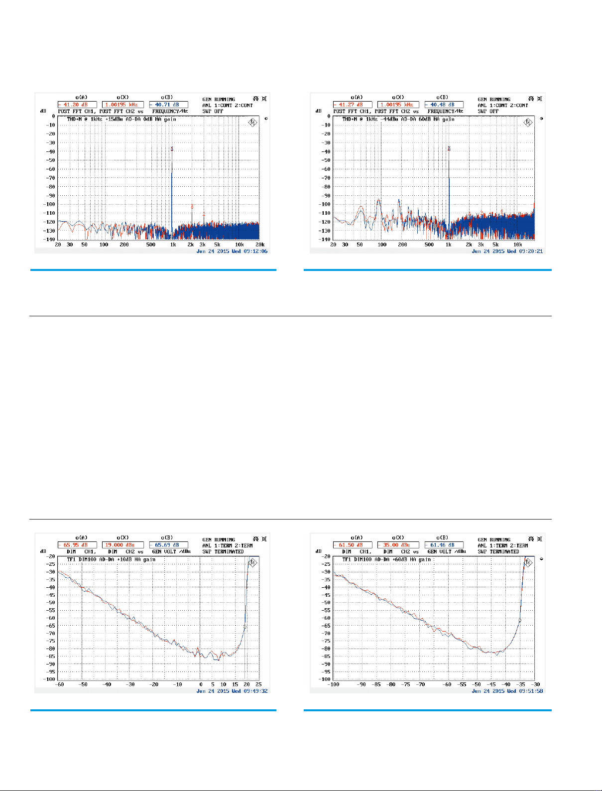
special cases. The curves in figures 8 and 9 demonstrate the
proportional signal distortion (y-axis) as a function of input level
(x-axis). Both curves show the THD (red), the sum of all har-
monic distortions and the THD+N (blue), i.e. all signal shares
not deriving from the signal source including noise.
When you measure at low test signal levels, the share of noise
and distortion will, necessarily, be high. When you increase
the test signal levels, THD and THD+N will decrease more and
more up to the point, where the clipping threshold is reached.
The minimum of the curve is mostly close to or directly at the
clipping threshold. In figure 8, the clipping threshold for 0 dB
gain is reached at +25 dBu, a point with very low distortion
values of –90 dB (= 0.003 %). The distortion minimum is
reached at a marginally lower level of 10 dBu and also really
great –110 dB (= 0.0003 %). Reaching these good values is a
bit more dicult when the preamp is confronted with higher
gain settings, here + 60 dB. Still, the figures are, nevertheless,
quite good compared to measuring at 0 dB. You’ll find the cor-
responding curves in figure 9.
In addition to the absolute distortion values their spectral struc-
ture is quite interesting. The desired harmonic distortion spec-
trum should, of course, have low distortion values but also the
lowest possible number of uneven (k3, k5, …) distortion shares
descending as quickly as possible towards higher order.
Ideal would be some k2, significantly less k3and, preferably,
nothing higher than that. The harmonic distortion spectra for
a sine wave at 1 kHz were measured at 0 and at +60 dB gain
(figures 10 and 11). The test signal level was always 10 dB
below the clipping threshold. Both spectra are quite close to
the ideal targeted values and should guarantee a great sound
quality of the preamp.
The third of the measurement series deals with transient in-
termodulation distortion, also known as TIM or DIM. The test
procedure is the same as in the THD measuring with only one
difference: the test signal is not a sinusoidal one but a mix of
sinus signal and rectangular pulse. This kind of test signal with
its steep rectangular pulse is far more challenging for the
tested circuit than the sinusoidal signal. That is why the DIM
test results are said to be more relevant for evaluating sound
qualities than just measuring THD. DIM values of –80 dB are
Preamp Gain 0 dB THD (red) und THD+N (blue), clipping threshold
is at +25 dBu input level (figure 8)
Gain set to +60 dB THD (red) and THD+N (blue), then clipping
threshold is at –35 dBu input level (figure 9)

Distortion of the TF1 at 0 dB gain and +15 dBu input level
(figure 10)
Distortion at 60 dB gain and –44 dBu input level (figure 11)
DIM transient intermodulation distortion at minimum gain (figure
12)
DIM transient intermodulation distortion at maximum gain (figure
13)
already considered to be really good. DIM curves for 0 and
60 dB preamp gain are shown in figures 12 and 13. The excel-
lent minimum of –85 dB in both cases was measured at ap-
proximately 10 dB below the maximum volume. So, again:
really outstanding results!
Signal processing and structure
Digital equipment has the advantage that the order of the
blocks of signal processing can be chosen quite flexibly. The
same goes for the taps in a signal path, e.g. where the signal
8|PRODUCTION PARTNER 09/2015
Test | Yamaha TF

PRODUCTION PARTNER 09/2015 |9
for the aux busses is generated. The signal path of a channel
strip is structured as follows: input selection, digital gain, high
pass filter, 4 band parametric EQ, gate, compressor and DCA
(fader). In Input Select the selection “Slot In 1–32” is still greyed
out because it will be activated in the desk’s firmware along with
the release of the NY64 expansion cards.
The tap for recording to a DAW connected via USB can be
switched globally. As a rule you’ll use pre-processing setup be-
cause the settings for a LIVE show are normally not the ones
you’ll want for a later downmix to a stereo file. Should you like
to do the downmix using the console again, you can play back
the unprocessed signals to the same position and then perform
the mix. To play back a multi-track recording of a concert is
sometimes quite convenient because you can use the recording
for a sound check on an empty stage. This is advantageous in
several ways:
Firstly, the musicians don’t have to go through a boring and tir-
ing sound check and, secondly, the sound engineer at the con-
sole can kind of get a good LIVE feeling while doing the sound
check (we all know that many musicians play louder and heavier
during a show than when doing the sound check).
Filters
Each input channel of the TF consoles features an adjustable
20 Hz to 600 Hz high pass filter and a 4-band fully parametric
EQ, which can, either, all be defined as Bell filters, or, alterna-
tively, one as high or one as low-shelf filter. The new user inter-
face for the filter section has turned out great: You can enter all
data directly, using the physical encoders, or just use the touch
panel controls (one or two finger mode). Using one finger you
can adjust gain or frequencies, with two fingers you can alter
the filter’s quality factor. The same can be done using the iPad
app. The TF editor transfers all three controls to the mouse
wheel; real purists or techno nerds then have the chance to
enter all filter parameters directly as numeric values.
Typical for Yamaha: the filters are not compensated with respect
to their transfer function. Close to half of the sampling rate, the
filter curve will be compressed while sweeping the frequency
axis. The reason is that the infinite frequency axis is transformed
from the analog to the finite and discrete spectrum of the digital
domain.
Is the half sampling rate at 24 kHz, you will already see signifi-
cant changes in the filter curve shape above 10 kHz. This is
clearly depicted by the two red curves in the upper part of figure
Parametric EQs in all inputs fully equipped, alternatively the EQ
can be set to “1-knob” mode (figure 14)
High and low shelving filters and high pass and low pass filters
(below) in all inputs (figure 15)
Bell-Filter with settings for frequency and gain (above) and for
quality (figure 16)

16. You can also notice this effect by looking at the filter curves
in the display. It is important to realize, that this is not some-
thing like distortion but only a slightly changed filter function,
which deviates from familiar analog behavior. Other manufac-
turers compensate this effect mathematically-feasible up to
reaching the cut-off frequency. Yamaha, traditionally, refrains
from using this compensation method – as usual, it’s, more or
less, a matter of taste.
At all console outputs you will also find graphic 1/3-octave EQs
in addition to the parametric filters. Due to the high number of
filters, the graphics EQs have been implemented as so-called
12 out of 31 filters to reduce the crucial computational power
requirements: Out of 31 a maximum of 12 frequency bands can
be used actively within the range of 20 Hz to 20 kHz. That’s
usually sucient in practice. The curve shape altering effect
close to half of the sampling rate can also be noticed when
looking at the 1/3-octave EQs. Due to the high bandwidth of the
respective filters there is some distinct overlapping. Operating
adjacent filters will therefore lead to strong cuts or boosts
which you have to be aware of.
Dynamic and Effect Functions
At each input of the TF desks there is a compressor/limiter in
combination with a gate; at the outputs you’ll only find com-
presssors/limiters. Again, the design of the user interface is
clear; everything is neatly arranged and easy to operate. You
can gather from figure 20 what effects different settings will
have. The figure shows the compressor reaction to a sine burst
with time constants of 50 and 500 ms for attack and release.
The threshold level of –20 dB here refers to 0 dBfs in the dig-
ital domain.
The two FX buses and – if required – also the six Stereo Aux
busses numbers 9 to 20 can be fed from all inputs. All respec-
tive masters comprise four band fully parametric EQs and sev-
eral effects; you will have varied reverb programs, delays, cho-
rus effects and a multiband compressor with four bands at your
disposal. If you like to use your own special effects you can
feed them in via the FX or Aux outs and return them via two
inputs of your choice.
1-knob functions and facilitations
To users who just want to use the desk as soon as possible,
the TF series offers a lot of features facilitating operation. For
input channels you’ll find ample libraries with preset filter and
compressor settings to record all kinds of instruments. These
presets are combined with mic recommendations made by
renowned microphone manufacturers like Audio-Technica,
Sennheiser or Shure (including optimized settings for the re-
spective recordings with particular mics). You can also create
your own libraries or modify existing ones.
For a desk novice, adjusting gain settings of the preamps often
proves to be the greatest challenge. You don’t want to set the
levels too low and, maybe, cause noise but, on the other hand,
you have to avoid clipping at all costs. A great help is offered
here by the TF consoles’ novel GainFinder function. Finding a
10 |PRODUCTION PARTNER 09/2015
Test | Yamaha TF
Graphic 1/3EQs in the outputs (figure 17)
Graphic EQ single filter bands from 20 Hz to 20 kHz (20 kHz Band
in red), below filter ranging from 500 Hz to 2 kHz single (green)
and en bloc (red) with +5, +10 and +15 dB gain (figure 18)

PRODUCTION PARTNER 09/2015 |11
favorable setting with sucient headroom for signal peaks is clearly
facilitated by just using colored bar indicators.
Another very noteworthy and helpful innovation – not only for begin-
ners – is the 1-knob function for the parametric EQs. You can choose
between different settings, e.g. “Intensity” and “Vocals” for inputs, “In-
tensity” and “Loudness” for outputs. “Intensity” can be applied to all
filter functions and shrinks or expands a complete filter curve’s gain
settings. Let’s say you have a given filter setting and you switch into 1-
knob mode; the curves original shape will first be preserved with the
intensity faders set to 50. At lower values the whole curve will become
flatter and flatter, at higher values this process will boost the curve. At
the intensity setting of zero, the filter will be deactivated and at inten-
sity setting 100, gain settings will be doubled (i.e. a Bell filter, previously
at + 6 dB, will then be at + 12 dB. In figure 22, the red curve represents
the starting point. The green curves were measured at intensity set-
tings between 10 and 100.
There are pre-configured loudness filter settings, also adjustable be-
tween values of 0 to 100. The idea of a loudness filter is to compensate
one weakness of our ears: in case of relatively low levels they pick up
low and high frequency ranges less than midrange frequencies. So you
would increase loudness filtering when you have soft background
music, you would decrease filtering or switch “Loudness” off com-
pletely when the sound environment becomes louder and louder.
For inputs there is a preset “Vocal” filter with a 140 Hz high pass filter
and a slight cut of the low mids and a boost of the higher frequencies.
In addition to the use of filters, dynamic processing constitutes the most important
function of a mixing desk. Especially LIVE music often generates a large dynamic
range meaning you would wish a certain compression would take place. Also, there
are often problems with noise during quiet music passages due to open, unused
mics. By means of compressors loud signal peaks can be reduced and gates can
block unused mic channels. Both functions utilize thresholds that determine when
the signal processing will start. If the compressor threshold is exceeded the signal
will be attenuated in a controlled way. The ratio setting determines the intensity
of attenuation. When all values are radically cut off above the threshold, then a
limiter as a special type of compressor is in use. The gate will react in a reverse
way, i.e. reduce the level or shut off the signal path completely when the values
fall below the threshold.
Both functions imply time constants. The attack time determines how fast a
reaction to exceeding or falling below the threshold will take place. The hold time
defines how long processing will still happen when exceeding or falling below the threshold level has stopped and the
release time defines, how fast the level will return to the initial state after the end of the hold phase.
⎮
Dynamic Processing
Controlling compressors YAMAHA TF
series (figure 19)
1-knob mode adjustments for parametric EQ in the out-
puts set to “Loudness” (figure 21)
Compressor reacting to a sine burst at 50 ms attack and
500 ms release for a threshold set to –20 dBfs (figure
20)

Compressor operation is also simple using the 1-knob function.
For fixed time constants and a ratio of 2:1 you can use the
1-knob parameter to set a combination of threshold and output
gain. The signal will be moderately compressed and then
again the overall level boosted, or, to put it simply, it will seem
to be “louder”.
Summary
The three TF series consoles expand Yamaha’s product range
of digital mixing desks in the lower price segment. All 3 models
are equipped in a way that enables you to use the consoles’
16, 24 respectively 32 Mic/Line inputs without any further ac-
cessories. Users who want to get rid of their old multicore after
acquiring one of the new consoles can use the NY64-Dante
Expansion card and Dante stage boxes (launch in spring 2016)
to create an up-to-date audio network in a simple and secure
way. Handling is equally easy and state-of-the-art. The desks
feature a big touch panel, an editor software for computers as
well as remote apps for iPad and iPhone, thus making them
really convenient and very useful for technicians and musi-
cians. Yamaha experts have also deliberated thoroughly about
how to facilitate getting started for beginners. That is why they
have included ample libraries with predefined channel settings
for all kinds of instruments and established microphone mod-
els, GainFinder for the inputs and the handy 1-knob mode for
parametric EQs and compressors.
All the technical tests have revealed that the TF desks offer
state-of-the-art technology and all measured values are awe-
some.
The very reasonable sales prices of € 2,975 (TF1), € 3,570
(TF2) and € 4,165 (TF3) give customers the chance to get a
great, open mixing desk system that can be enormously and
flexibly expanded using a simple and adaptable Dante net-
work.
12 |PRODUCTION PARTNER 09/2015
Test | Yamaha TF
1-knob filter set to “Intensity” (upper), “Loudness” (middle) and
adjusted for vocals (lower) (figure 22)
Compressor 1-knob adjustment for quick access without irritating
or confusing beginners (figure 23)
Yamaha Music Europe GmbH
Siemensstr. 22 – 34
D-25462 Rellingen
www.yamahaproaudio.com
Other manuals for TF Series
1
This manual suits for next models
3
Table of contents
Other Yamaha Recording Equipment manuals

Yamaha
Yamaha QX 21 User manual

Yamaha
Yamaha TX-216 User manual

Yamaha
Yamaha MW8cx User manual

Yamaha
Yamaha EME-1 User manual

Yamaha
Yamaha TG300 User manual

Yamaha
Yamaha CDR-HD1000 User manual

Yamaha
Yamaha SPX1000 User manual

Yamaha
Yamaha MSS1 User manual

Yamaha
Yamaha QY70 Manual

Yamaha
Yamaha MDR-3 User manual

Yamaha
Yamaha D24 User manual

Yamaha
Yamaha QX1 User manual

Yamaha
Yamaha A4000 User manual

Yamaha
Yamaha FX900 User manual

Yamaha
Yamaha GEP50 User manual

Yamaha
Yamaha D1500 User manual

Yamaha
Yamaha ACU16-C User manual

Yamaha
Yamaha VL1-m User manual

Yamaha
Yamaha FX500B User manual

Yamaha
Yamaha CRW2260t Series User manual