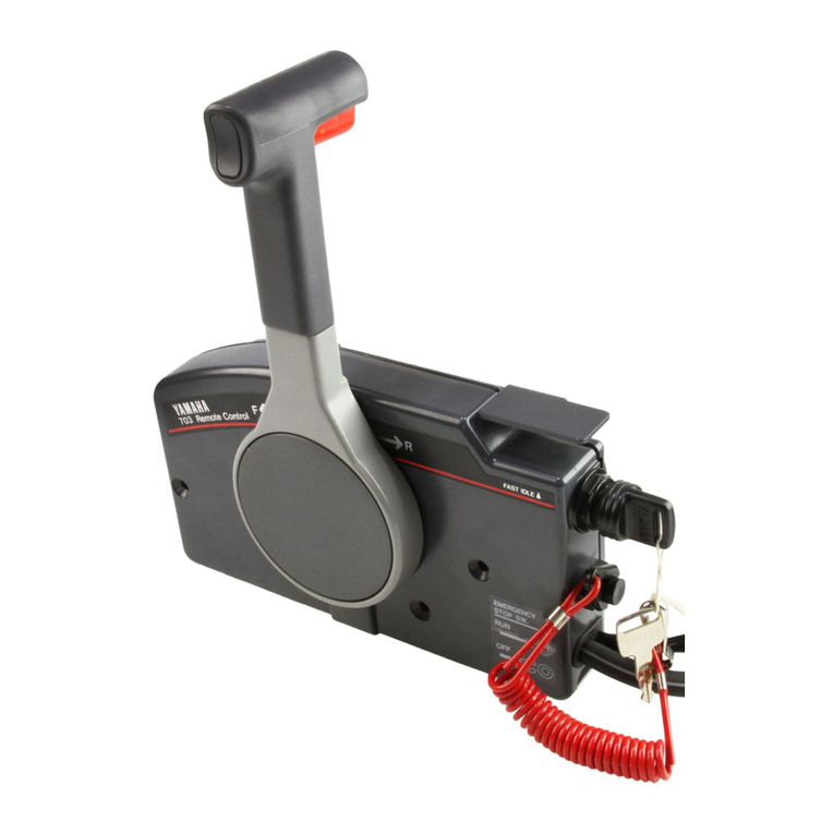
Yamaha Outboards 703 User manual

Marine
Outboards
703
REMOTECONTROLBOX
OPERATIONMANUAL
MODED'EMPLOIDEBOITIER
DECOMMANDEA DISTANCE
"T
YAMAHAMOTORCO.,LTD.
703-28199-33•
http://motorka.org

NOTICE
CONTENTS
1
TABLEDESMATIERES
AVIS1
NOMENCLATURE NOMENCLATURE
OPERATION.2
UTILISATION«...2
REMOTECONTROLBOX
POSITIONINGAND
CABLELENGTH.. 6
INSTALLATION7
CHANGEINTHECONTROL
LEVERPOSITION10
CHANGEFROMTHEPUSH-
TO-OPENTHROTTLETYPE
TOTHEPULL-TO-OPEN
THROTTLETYPE. 12
THROTTLEOPENING
ADJUSTMENTAT
REVERSE 15
POSITIONNEMENTDU
BOITIERDECOMMANDEA
DISTANCEETLONGUEUR
DESCABLES. . 6
POSE
REMOTECONTROLBOX
FORTWIN-ENGINE15
CHANGEMENTDELA
POSITIONDULEVIER
DECOMMANDE10
CHANGEMENT
D'ACCELERATEURDU
TYPEPOUSSERPOUR
OUVRIRAUTYPETIRER
POUROUVRIR.12
REGLAGEDE
LOUVERTUREDE
L'ACCELERATEUREN
MARCHEARRIERE15
NOTESONSTORAGE. ...16
WIRING16
BOITIERDECOMMANDEA
DISTANCEPOURDEUX
MOTEURS15
REMARQUESCONCERNANT
LEREMISAGE16
SCHEMAELECTRIQUE...16

NOTICE
Thisremotecontrolboxissodesignedthatbothclutchand
throttlecanbeactuatedbyoperatingtheremotecontrol
lever.Forthecorrectoperationandinstallationofthe
remotecontrolbox,pleasereadthismanualcarefullyand
thoroughly.
Particularlyimportantinformationisdistinguishedinthis
manualbythefollowingnotations.
A TheSafetyAlertSymbolmeansATTENTION!
BECOMEALERT!YOURSAFETYISINVOLVED!
AWARNING
FailuretofollowWARNINGinstructionscouldresult
insevereinjulyordeathtothemachineoperator,a
bystander,ora personinspectingorrepairingthere-
motecontrolbox.
HMHi
ACAUTIONindicatesspecialprecautionsthatmustbe
takentoavoiddamagetotheremotecontrolbox.
NOTE:
ANOTEprovideskeyinformationtomakeprocedureseasi-
erorclearer.
Specificationsgiveninthismanualmaybesubjectto
changewithoutnotice.
AVIS
Ceboitierdecommandea distanceestcon<?udemaniere
tellequel'inversionetl'accelerationpeuventetreactivees
enactionnantlelevierdecommandea distance.Pour
1'utilisationetlemontagecorrectsduboitierdecommande
adistance,veuillezlirecemanuelsoigneusementeten
totalite.
Danscemanuel,lesinformationsparticulierementimpor-
tantessontdistingueesparlesnotationssuivantes:
Cesymbolesignaleundangeretsignifie:
/KATTENTIONDANGER!SOYEZATTENTIF!
VOTRESECURITEESTENJEU!
AAVERTISSEMENT
LerespectdesconsignesAVERTISSEMENTestimperatif,
fautedequoileconducteur,toutepersonnesetrouvanta
proximiteoulepersonnelchargedePentretiencommande
adistancerisqueraitd'etregrievementvoiremortellement
blesse.
ATTjEMTI©§§
ATTENTIONindiquelesconsignesquidoiventetrerespec-
teesafind'eviterd'endommagerlesystemedecommandea
distance.
N.B.:
N.B.donnedesinformationsimportantesquifacilitentet
expliquentlesdifferentesoperations.
Lescaracteristiquesdonneesdanscemanuelpeuventetre
changeessansavisprealable.
NOMENCLATURE NOMENCLATURE
©Grip
(2)Lockbutton
(3)Powertrimandtiltswitch
(4)Neutralthrottlelever
(5)Mainswitch
(6)Enginestopswitch
(7)Wireharness
(8)Throttlefrictionscrew
(9)Controllever
(T)Poignee
(2)Boutondeverrouillage
(3)Interrupteurdedispositifd'inclinaisonetderelevage
assistes
(?)Levierd'accelerationaupointmort
(5)Contacteurprincipal
(6)Coupe-circuitdesecurite
(7)Faisceauelectrique
(8)Visdereglagedefrictiond'acceleration
(9)Levierdecommande
NOTE:
•Dependingonthespecification,somemodelsarenot
equippedwiththepowertrimandtiltswitch.
•Typewithoutchokeswitchisavailable.
N.B.:
•Suivantlaspecification,certainsmodelesnesontpasmunis
del'interrupteurdedispositifd'inclinaisonetderelevage
assistes.
®Lemodelesansinterrupteurdestarterestdisponible.
-1-

OPERATION
1.ForwardandReverse
Toshiftintoforwardandreverse,turnthecontrollever
downwardabout32°(detentposition)totheF sideandR
side,respectively.Whenthecontrolleverisfurtherturned
downward,thethrottleopens.
r—CAUTION
Ifthelockbuttonisnotfullypulledup,thecontrollever
willnotturnfurtherfromtheneutralposition.
UTILISATION
1.MarcheAvantetMarcheArriere
Pourenclencherlamarcheavantoulamarchearriere,
tournerrespectivementlelevierdecommandeverslebas
d'environ32°(positiondedetente)verslecoteF ouR.
Quandlelevierdecommandeesttournedavantageversle
bas,l'accelerateurs'ouvre.
—ATjm^mt
Sileboutondeverrouillagen'estpascompletementtire
verslehaut,lelevierdecommandenepourrapasetre
tourneaudeladupointmort.
ForwardShift.
MarcheavantInversion
^32°
zFull-closed
ThrottleFermeture
Acceleration
Neutral
Pointmort
IS|ShiftReverse
InversionMarche
Full-closedXXeation
Full-open
Ouverture
maximale
Ouverture
maximale
2.Free-Accelerator
Placethecontrolleverintheneutral(N)andturnthe
neutralthrottleleverupward,thethrottlecanbeopened
withoutshiftingintoanygear.
Usetheneutralthrottleleverwhenstartingorwarmingup
theengine.
r-CAUTION:
Onlywhenthecontrolleverintheneutralposition,the
neutralthrottlelevercanbeoperated.Withoutreturn-
ingtheneutralthrottleleverintheclosed-position(ina
horizontalposition),thecontrollevercannotbe
operated.
2.LevierdeLibreAcceleration
Mettrelelevierdecommandeaupointmort(N)ettourner
lelevierd'accelerationaupointmortverslehaut;
l'accelerateurpeutetreouvertsansenclencherlamarche
avantoulamarchearriere.
Utiliserlelevierd'accelerationaupointmortpourdemarrer
oufairechaufferlemoteur.
—^rimmm^
Lelevierdecelerationaupointmortnepeutetre
actionnequelorsquelelevierdecommandeestaupoint
mort.
Deplus,lelevierdecommandenepeutpasetreactionne
sansremettrelelevierd'accelerationaupointmorten
positiondefermeture(levierhorizontal).
Full-open
Ouverturemaximale
-2-

3.OperationofSwitches
1)Mainswitch
(1)-1Electricalcircuitsstartingengine
Byturningthekey,theelectricalcircuitcanbeopened
andclosed,andtheenginecanbestarted.
NOTE:
WhenthekeyisreleasedatSTART,itwillreturntoON
automatically.
(1)-2Choke
Whenpressinginthemainswitchat"ON"or"START"
positionasshownbythearrow"—"intheillustration
totheright,theremotechokesystemwilloperate.
NOTE:
•Somemodelsarenotequippedwiththeremotechoke
system.
3.UtilisationdesInterrupteurs
1)Contacteurprincipal
(1)-1Circuitselectriques-demarragedumoteur
Entoumantla cle,lecircuitelectriquepeutetreouvertet
ferme,etlemoteurpeutetredemarre.
N.B.:
QuandonrelachelacledelapositionSTART,ellerevient
automatiquementsurlapositionON.
(l)-2Starter
Lesystemedestartera distanceestactionnelorsquevous
enfoncezlecontacteurprincipalenposition"ON"ou
"START"commeindiqueparla fleche"—dans
illustrationdedroite.
N.B.:
•Certainsmodelesnesontpasequipesdusystemedestartera
distance.
OFFONSTART
\
ewttfiewcY•
FT
OPSW.
RUN
—<§)
,ON
RD4-
I
2)Emergencystopswitch
Theemergencystopswitchisprovidedforthesafetyof
theoperator.Whenthelockplateispulledoutfromthe
emergencystopswitch,theenginestopsimmediately.
Theenginewillnotstartwhenthelockplateisremov-
ed.Shouldtheoperatorfallofftheboatorleantoofar
overoneside,thelockplatewillpull outcausingthe
enginetostop.
2)Coupe-circuitdesecurite
Cecoupe-circuitestprevupourlasecuritedel'utili-
sateur.Quandlafourchettedeverrouillageestenlevee
ducoupe-circuitdesecurite,lemoteurs'arreteimmedia-
tement.Quandlafourchetteestenlevee,lemoteurne
peutpasetredemarre.Sil'utilisateurtombedubateau
ousepenchetropd'uncote,lafourchettedeverrouil-
lages'enleveetentraineainsi1'arretdumoteur.
WARNING:
Whenstartingoroperatingtheengine,besureto
tietheSockplatecordtoyourbody.
AVERTISSEMENT:
Quandondemarreouutiliselemoteur,nepasoublier
des'attacherlaficelledelafourchetteau corps.
(T)Lockplate (T)Fourchette

3)Powertrimandtiltswitch
Thepowertrimandtiltswitchisattachedtothecontrol
levergrip.Pushingituptrimsupandtiltsuptheengine,
andpushingitdowntrimsdownandtiltsdownthe
engine.
NOTE:
Whiletheswitchbuttonisbeingpressed,thetrim/tilt
motorturnsandadjuststheenginemountingangle.When
theswitchbuttonisreleased,theenginewillstopinits
position.
3)Interrupteurdedispositifd'inclinaisonetderelevage
assistes
Cetinterrupteurestintegrea lapoigneedulevierde
commandea distance.L'appuisurlehautfaitmonterle
moteur,etl'appuisurlebaslefaitdescendre.
N.B.:
Quandonappuiesurleboutondecetinterrupteur,le
moteurd'inclinaison/derelevagetourneetregiel'anglede
fixationdumoteurhors-bord.Quandonrelachelebouton,
lemoteurs'arrete.
4.AdjustingtheStiffnessoftheControlLever
Byturninginoroutthethrottlefrictionscrewatthefrontof
theremotecontrolbox,thestiffnessofthecontrollever
canbeadjusted.Turningthescrewtotherightmakesthe
controlleverstifftoturn,andturningittotheleftmakes
theleverlight.
4.ReglagedelaDureteduLevierdeCommande
Laduretedulevierdecommandepeutetreregleeenvissant
oudevissantlavisdefrictiond'acceleration.Larotationde
lavisversladroiterendlelevierdecommandedura
tourner,etlarotationdecettevisverslagaucheadoucitla
rotationduditlevier.
\w
Makelight
Pouradoucir
Makestiff
Pourdoucir
—4—

5.OverheatWarningBuzzer
Thesensorinstalledontheenginesidecausestheoverheat
warningbuzzertosoundwhentheengineisgoingto
overheat.
AWARNING
Shouldtheoverheatwarningbuzzersound,turnin
thethrottlegripimmediatelytoslowdownthe
enginetoidlingspeedsothatitcoolsdown.Then,
saildirecttoyournearestportatlowspeeds.
5.VibreurdeSignalisationdeSurchauffe
Lasondesitueesurlemoteurfaitretentirlevibreurde
signalisationdesurchauffequandlemoteurestsurlepoint
desurchauffer.
AAVERT1SSEMENT
Silevibreurdesignalisationdesurchaufferetentit,
fermerimmediatementlapoigneed'accelerationpour
fairetournerlemoteurauralentietluipermettreainsi
derefroidir.Ensuite,rentrerdirectementauportleplus
prochea faiblevitesse.
NOTE:NoB.:
Typewithoutoverheatwarningbuzzerisavailable.Lemodelesanssignalsonoredesurchauffeestdisponible.
6.NeutralSwitch
Theneutralswitchkeepstheenginefromstartingwith
gearsareshiftedin.WhenthecontrolleverisinForwardor
Reverse,theenginecannotbestartedbyoperatingthe
mainswitch.
6.ContacteurdePointMort
Lecontacteurdepointmortempechelemoteurde
demarrerquandlamarcheavantoulamarchearriereest
enclenchee.Quandlelevierdecommandeestenmarche
avantouenmarchearriere,lemoteurnepeutpasetre
demarreenactionnantlecontacteurprincipal.
(T)Overheatwarning
buzzer
(J)Vibreurdesignalisation
desurchauffe
(T)Neutralswitch (T)Contacteurdepointmort
-5-

REMOTECONTROLBOXPOSITIONING
ANDCABLELENGTH POSITIONNEMENTDUBOITIERDECOM-
MANDEA DISTANCEETLONGUEURDES
CABLES
AWARNING
Incorrectselectionorinstallationofa remotecon-
trolmayresultinsuddenandunexpectedlossof
control,thusresultingina seriousaccident.
PleaseconsultyourYamahadealer.
AAVERTISSEMENT
Unmauvaischoixdecommandea distanceouune
mauvaiseinstallationpeuventsetraduireparuneperte
decontrdlesoudaineetfortuite,entrainantainsiun
accidentgrave.Veuillezdoneconsultervotredistribu-
teurYamaha.
1.RemoteControlBoxPosition
Theremotecontrolboxshouldbesetina positioninwhich
itdoesnotobstructtheoperationsofthecontrolleverand
switches.Makesurethereisnoobstructiononthepathof
theremotecontrolcables.
2.RemoteControlCableLength
Measurethedistancefromthe©point(thecenterofthe
remotecontrolbox)tothe© point(thecenterofthe
engine)throughthe(B)point(acornerofthetransom).Add
300mm(1foot)tothisdistance.Thecablelengthshould
beequaltothesum.Positiontheremotecontrolcablesand
checkiftheyarelongenough.Connectthecablestothe
engineandmakesuretheydonotgettangledorbentwhen
thesteeringwheelisturned.
—CAUTION:
Avoidbendingthecablessharply;thatis,makesurethe
cablesdonotfroma loopwitha diameteroflessthan
406mm(16in).
1.PositionduBoitierdeCommandea Distance
Leboitierdecommandea distancedoitetremisdansun
endroitouilnegenepasPutilisationdulevierdecommande
etdesinterrupteurs.S'assurerqu'iln'ya pasd'obstaclesur
letrajetdescablesdecommandea distance.
2.LongueurdesCablesdeCommandea Distance
Mesurerladistancedupoint(§)(centreduboitierde
commandea distance)aupoint© (centredumoteur)en
passantparlepoint(g)(uncoindutableauarriere).Ajouter
300mm(1pied)a cettedistance.Lasommeainsiobtenue
corresponda lalongueurdescables.Positionnerlescables
decommandea distanceetcontrolers'ilssontassezlongs.
Raccorderlescablesaumoteurets'assurerqu'ilsne
s'embrouillentounesetordentpasquandlevolantest
tourne.
—ATTENTION:
Eviterdetropcourberlescables;leurdiametrede
courburenedoitpasetreinferieura 406mm(16po).
-6-

INSTALLATION
1.Pinchthewirecoverwithyourfingersandpullitoutto
remove.
POSE
1.Saisirlesdeuxcotesducachedecablesetletirerpour
l'enlever.
®Wire
c
(T)Cachedecables
2.Loosenthetwoscrews,andremovethelowerback
panel.
2.Enleverlesdeuxvisetenleverledosinferieur.
(T)Backpanel ®Dos
3.Screwinthecablejoints(accessories)about11mm(0.4
in)overtheendsoftheremotecontrolcables,andtighten
thelocknuts.Beforeinstallingthecablejoints,applythe
water-resistancegrease(YamahaGreaseA)totheholesin
thecablejoints.
3.Visserlesraccordsdecable(accessoires)d'environ11
mm(0,4po)surlesextremitesdescablesdecommandea
distancepuisserrerlescontre-ecrous.Avantdemonterles
raccordsdecable,mettredelagraisseetanche(Graisse
YamahaA)dansleurstrousfiletes.
<•0
Applygrease
Graisser
(7)Remotecontrolcable
(2)Locknut
(3)Cablejoint^ o,
11mm(0.4in)
(T)Cabledecommandea distance
(2)Contre-ecrou
(3)Raccorddecable
-7-

4.Inserttheremotecontrolcableouterforshiftingintothe
housingclampsothatthegrooveonitsendfitsoverthe
ridgeintheclamp.Fitthecablejointoverthepinonthe
endoftheshiftarm,andlockitwiththecirclip.
5.Fitthegrommet(accessory)intheclampgroove.
4.Insererlagaineducabledecommanded'inversiona
distancedanslabrideduboitierdemanieretellequela
gorgedesonextremites'ajustesurlanervuredelabride.
Ajusterleraccorddecablesurlagoupillederextremitedu
brasd'inversionpuislebloqueraveclecirclip.
5.AjusterPoeilletencaoutchouc(accessoire)danslagorge
delabride.
(T)Grommet
(2)Clampgroove
(3)Circlip
(4)Shiftarm
(T)Oeilletencaoutchouc
(2)Gorgedelabride
(3)Circlip
(4)Brasd'inversion
6.Connecttheremotecontrolcableforthethrottletothe
throttlearminthesamemanner.
6.Raccorderlecabledecommanded'accelerationa
distanceaubrasd'accelerationdelamememaniere.
(T)Remotecontrolcable
forthrottle
(2)Remotecontrolcable
forshifting
(3)Circlip
(T)Cabledecommande
d'accelerationa distance
(2)Cabledecommanded'inversion
adistance
(3)Circlip
—8—

7.Securethelowerbackpanelwiththetwoscrews,and
installthewirecover.
8.Afterconnectingtheremotecontrolcables,installthe
remotecontrolboxinthepreviouslydeterminedposition
usingtheaccessoryfittings(screws,nuts,washers,and
spacer).
TIGHTENINGTORQUE:
1.2-1.5Nm(0.12-0.15m-kg,0.87-1.1ft-lb)
7.Fixerledosinferieuravecsesdeuxvispuismonterle
cachedecables.
8.Apresavoirraccordelescablesdecommandea distance,
monterleboitierdecommandea distancea l'endroit
prealablementdeterminea l'aidedespiecesaccessoires(vis,
ecrous,rondellesetentretoise).
COUPLEDESERRAGE:
1,2
—
1,5Nm(0,12-0,15m-kg,0,87-1,1ft
•
lb)
(T)Remotecontrolbox © Boitierdecommande
©Screw © adistance
(3)Spacer © Vis
(4)Washer © Entretoise
(5)Nut © Rondelle
(6)Hull © Ecrou
© Coque
9.Accordingtotheinstructionsgivenintherespective
owner'smanualofoutboardmotor,connecttheremote
controlcablesbothforshiftingandthrottleand
wireharnesstotheengine.Whenconnecting,setthecon-
trollevertoN,andplacetheneutralthrottleleverinthe
closedposition(horizontal).
10.Byoperatingthecontrollevera fewtimes,checktosee
thatwhentheleveristurnedtoForwardorReverseuntilit
stopsonce(about32°),thegearshifts,andthatwhenthe
leveristurnedfurtherfromthispositiontoForward,the
throttlefullyopens.Next,makesurethatwhenthecontrol
leverisreturnedtoN,thethrottleiscompletelyclosed.If
notfullyclosed,adjustthepositionsofcablejointsonthe
engineside,andinstallthemagain.
9.ConformementauxinstructionsdonneesdansleManuel
duproprietairedumoteurhors-bord,raccorderlescables
decommanded'inversionetd'accelerationa distanceetle
faisceauelectriqueaumoteur.Lorsduraccordement,
mettrelelevierdecommandeaupointmort,etmettrele
levierd'accelerationaupointmortenpositiondefermeture
(levierhorizontal).
10.Enactionnantlelevierdecommande,controlersila
marcheavantetlamarchearrieresontenclencheesquandil
esttourneverslapositioncorrespondantejusqu'acequ'il
s'arrete(environ32°).Contrdleraussisil'accelerateur
souvreaumaximumquandlelevieresttournedavantagea
partirdecettepositionenmarcheavant.Ensuite,s'assurer
quel'accelerateurserefermecompletementquandlelevier
decommandeestremisaupointmort.Sil'accelerateur
n'estpascompletementferme,reglerlespositionsdes
raccordsdecabledumoteuretlesremettreenplace.
—ATTENTION:
Thecablejointsontheenginesidemustbescrew-
ed inatleast8 mm(0.3 in)overtheremotecontrol
cables.
—ATTENTION:
Lesraccordsdecabledumoteurdoiventetrevissesd'au
moins8 mm(0,3po)surlesextremitesdescablesde
commandea distance.
-9-

CHANGEINTHECONTROLLEVERPOSI-
TION
Theremotecontrolboxpermitstochangethecontrollever
positionfromtherightsidetotheleftsideorviceversa.
1.Pinchthewirecoverwithyourfingers,andpullitoutto
remove.
2.Usinga socketwrench(12mm),loosenthebolt.
CHANGEMENTDELAPOSITIONDULEVI-
ERDECOMMANDE
Ceboitierdecommandea distancepermetdechangerla
positiondulevierdecommandeducotedroitaucote
gauche,ouviceversa.
1.Saisirlesdeuxcotesducachedecablesetletirerpour
Tenlever.
2.A l'aided'uneclea douillede12mm,desserrerle
boulon.
3.Placea punchonthebolthead,andbytappingitwitha
hammer,removethecontrolleverfromtheremotecontrol
box.
r—CAUTION:'
Usecarenottodamagepowertrimandtiltswitch
leads.
3.Mettreunpointeausurlateteduboulonet,entapant
dessusavecunmaillet,enleverlelevierdecommandedu
boitierdecommandea distance.
—ATTENTION:
Prendregardea nepasendommagerlesfilsde
l'interrupteurdedispositifd'inclinaisonetderelevage
assistes.
-10-
http://motorka.org

4.Loosenthetwoscrews,andremovetheneutrallock4.Enleverlesdeuxvisetenleverlesupportdeverrouillage
holder.depointmort.
(T)Neutrallockholder (T)Supportdeverrouillage
depointmort
5.Placetheremotecontrolboxupsidedown,andsecure
theneutrallockholderwiththetwoscrews.
5.Retournerleboitierdecommandea distancepuisfixerle
supportdeverrouillagedepointmortavecsesdeuxvis.
TIGHTENINGTORQUE:
3-4Nm(0.3- 0.4m
•
kg,2.2- 2.9ft
•
lb)
COUPLEDESERRAGE:
3
- 4 Nm(0,3- 0,4m
•
kg,2,2- 2,9ft• lb)
V
en (JlilL
®0 w ®
V
en
0e ^Lh ®
I
|f
6.Installthecontrollever,andsecureitbyscrewinginthe
boltfromthebacksideandwiththewasher. 6.Monterlelevierdecommandeetlefixerenvissantle
boulon,munidesarondelle,parderriere.
TIGHTENINGTORQUE:
10-11Nm(1.0-1.1m-kg,7.2-7.9ft-lb) COUPLEDESERRAGE:
10-11Nm(l,0~1,1m-kg,7,2-7,9ft-lb)
7.Whiletakingcaresothatthepowertrimandtiltswitch
leadsarenottwistedorslackened,installthewirecover. 7.Toutenprenantgardea cequelesfilsdel'interrupteur
dudispositifd'inclinaisonetderelevageassistesnesoient
pasvrillesouaplatis,monterlecachedecables.
-11-

CHANGEFROMTHEPUSH-TO-OPEN
THROTTLETYPETOTHEPULL-TO-OPEN
THROTTLETYPE
Theremotecontrolboxpermitstochangefromthepush-
to-openthrottletypetothepull-to-opentypebychanging
someofthepartsandtheirpositions.
Thismanualdiscussestheprocedureforchangingfromthe
push-to-openthrottletypetothepull-to-openthrottletype.
Therefore,ifithastobechangedfromthepull-to-open
typetothepush-to-opentype,simplyreversethepro-
cedure.
r—CAUTION:
Whenreinstallingparts,applythewater-resistant
grease(YamahaGreaseA)tomovingpartsandcontact
surfacesofparts.
CHANGEMENTD'ACCELERATEURDU
TYPEPOUSSERPOUROUVRIRAUTYPE
TIRERPOUROUYRIR
Ceboitierdecommandea distancepermetdechanger
l'accelerateurdutypepoursserpourouvrirautypetirer
pourouvrirenchangeantcertainesdespiecesetleurs
positions.Cemanueldecritlaproceduredechangementdu
typepousserpourouvrirautypetirerpourouvrir.Par
consequent,sionveutchangerl'accelerateurdutypetirer
pourouvrirautypepousserpourouvrir,ilsuffitd'inverser
cetteprocedure.
—HMHB
Lorsduremontagedespieces,mettredelagraisse
etanche(GraisseYamahaA)surlespiecesmobilesetsur
lesfacesdecontactdespieces.
Forpulltoopenthrottle
L'accelerateurdetirer
pourduvrir
L'accelerateurdepousser
pourouvrir
1.Pinchthewirecoverwithyourfingersandpullitoutto
remove.
2.Loosenthescrews,andremovebothupperandlower
backpanels.
1.Saisirlesdeuxcotesducachedecablesetletirerpour
l'enlever.
2.Enleverlesvisetenleverlesdossuperieuretinferieur.
-12-

3.Loosenthetwoscrewsholdingtheneutralthrottlelever,
andremovethethrottledrum.Rotatethedrum180°,and
holdtheneutralthrottleleverwiththesamescrews.
3.Desserrerlesdeuxvisfixantlelevierd'accelerationau
pointmortpuisenleverletambourd'acceleration.Tourner
letambourde180°puisfixerlelevierd'accelerationau
pointmortavecsesvis.
NOTE:
Usecaresothattherollerdoesnotjumpoutduetospring
force.
N.B.:
Prendregardea cequelaforceduressortnefassepas
sauterlegalet.
TIGHTENINGTORQUE:
1.5~ 1.8Nm(0.15~ 0.18m
*
kg,1.1 -1.3ft- lb) COUPLEDESERRAGE:
1,5
—
1,8Nm(0,15~ 0,18m-kg,1,1~ 1,3ft-lb)
®Throttledrum
(2)Roller
Turnthedrum180°andinstallthelever.
Tournerletambourde180°puismooterlelevier. (T)Tambourdeceleration
(2)Galet
4.Removethethrottlearmforthepush-to-openthrottle
type,andinstallthethrottlearmforthepull-to-openthrot-
tletype.
4.Enleverlebrasd'accelerationdutypepousserpour
ouvriretmonterlebrasd'accelerationdutypetirerpour
ouvrir.
NOTE:
Replacethecamrollerattachedtothethrottlearmwith
thethrottlearmforthepull-to-openthottletype.
N.B.:
Changerlegaletdecamefixesaubrasd'accelerationavec
lebrasd'accelerationdutypetirerpourouvrir.
(T)Camroller (T)Galetdecame
-13-

5.Alignthemainshaftandthrottlearmwiththegrooves,
andalignthedrivepinwiththeslot,andsecuretheupper
backpanelwiththethreescrews.
5.Alignerl'axeprincipaletl'axedebrasd'acceleration
aveclesgorges,etalignerlagoupilled'entrainementavecla
fente.Ensuite,fixerledossuperieuravecsestroisvis.
TIGHTENINGTORQUE:
1.5-1.8Nm(0.15-0.18m -kg,1.1-1.3ft-lb) COUPLEDESERRAGE:
1,5-1,8Nm(0,15-0,18m-kg,1,1- 1,3ft•lb)
(T)Mainshaft
(2)Throttlearmshaft
(3)Drivepin
(T)Axeprincipal
(2)Axedebrasd'acceleration
(3)Goupilled'entrainement
6.Securethelowerbackpanelwiththetwoscrews,and
installthewirecover. 6.Fixerledosinferieuravecsesdeuxvispuismonterle
cachedecables.
——V®,
©e
ZB
^/ -v
(T)Backpanel ®Dos
-14-

THROTTLEOPENINGADJUSTMENTAT
REVERSE
1.Removethewirecover,loosenthescrews,andremove
theupperandlowerpanels.
2.Loosenthelocknut,andadjustthethrottlebyturning
theadjustbolt.Turningtheadjustbolttotheleftmakesthe
throttleopeninglarger,andturningittotherightmakesthe
openingsmaller.
AWARNING
REGLAGEDEL OUVERTUREDEL'ACCE-
LERATEURENMARCHEARRIERE
1.Enleverlecachedecables,enleverlesvisetenleverles
dossuperieuretinferieur.
2.Desserrerlecontre-ecrouetreglerl'accelerateurentour-
nantleboulondereglage.Larotationdeceboulonversla
gaucheaugmentel'ouverture;etlarotationversladroitela
diminue.
AAVERTISSEMENT
Ifthereversethrottleopeningistoolarge,itmay
leadtoanerrorincontroloperation.Set thecon-
trolleversothatitdoesnotturnmorethan60°to
theReverse.
SiFouvertilredel'accelerateurenmarchearriereest
tropgrande,celarisqued'entrainerunepertedecon-
trole.Reglerlelevierdecommandedemanieretelle
qu9ilnetoairaedasdeplusde60°verslapositionR
(marchearriere).
(T)Locknut
(2)Adjustingbolt
(T)Contre-ecrou
(2)Boulondereglage
3.Afteradjusting,tightentheadjustingboltlocknut. 3.Apreslereglage,resserrerlecontre-ecrouduboulonde
reglage.
TIGHTENINGTORQUE:
1.5-1.8Nm(0.15-0.18m kg,1.1~ 1.3ft-lb) COUPLEDESERRAGE:
1,5~ 1,8Nm(0,15~ 0,18m-kg,1,1- 1,3ft- lb)
4.Installbothupperandlowerbackpanels,andinstallthe
wirecover. 4.Monterlesdossuperieuretinferieuretlecachede
cables.
REMOTECONTROLBOXFORTWIN-ENGINE
Whenmountingtwoengines,usethetwin-engineremote
controlbox.
NOTE:
Eitherhalfofthetwin-engineremotecontrolcanbeused
independently.
BOITIERDECOMMANDEA DISTANCE
POURDEUXMOTEURS
Quandonmontedeuxmoteurs,utiliserleboitierdecom-
mandea distancepourmoteursjumeles.
N.B.:
Chaquemoitieduboitierdecommandea distancepour
moteursjumelespeutetreutiliseeindependamment.
®Screw
(2)Spacer
(3)Hull
(4)Washer
(5)Nut
(DRemotecontrolbox
®Vis
(2)Entretoise
(3)Coque
(4)Rondelle
(5)Ecrou
(6)Boitierdecommande
adistance
-15-
http://motorka.org

NOTESONSTORAGE
Toensurea longerlifeoftheremotecontrolbox,besureto
takethefollowingstepswhenstoringitfora longperiodof
time.
1)Removethecablejointsandapplywater-resistant
grease(YamahagreaseA)tothethreadedportionof
theinnercable.
2)Alsoapplywater-resistantgrease(YamahagreaseA)to
innerpartsoftheremotecontrolbox,particularlyto
contactsurfacesofmovingparts.
Ifanyrustisfound,removeitandapplythegrease.
3)Avoidbendingthecablesintoa loopasmuchaspossi-
ble.Butiftheyhavetobelooped,theloopdiameter
shouldbemorethanonemeter(40in).
4)Selecta dryplaceforstorage.
REMARQUESCONCERNANTLEREMISAGE
Pourassurerunemeilleurlongeviteduboitierdecom-
mandea distance,nepasoublierdeprocedercommesuit
avantdeleremiserpourunelongueduree.
1)Enleverlesraccordsdecableetmettredelagraisse
etanche(GraisseYamahaA)surlapartiefileteedes
cables.
2)Mettreaussidelagraisseetanche(GraisseYamahaA)
surlespiecesinternesduboitierdecommandea
distance,surtoutsurlesfacesdecontactdespieces
mobiles.S'ily a delarouille,l'eliminerpuisgraisser.
3)Eviterautantquepossibledecourberlescables,.S'ils
doiventetreenroules,lediametred'untourdoitetre
superieura unmetre(40po).
4)Choisirunendroitsecpourleremisage.
WIRING
NOTE:
Dependingonthespecification,somemodelsarenot
equippedwiththepowertrimandtiltswitch.
SCHEMAELECTRIQUE
N.B.i
Suivantlaspecification,certainsmodelesnesontpasmunis
de1'interrupteurdedispositifd'inclinaisonetderelevage
assistes.
•Typewitha full-lineofequipment
•Modeleaveclagammecompleted'equipment
Q> \ Sb R Lg
UP O O
FREE
DOWN O O
\ W B R Y Br PUSH
OFF O O
ON
START O O O -O •7OQ-Y
D>CJ-P-
\W B
OFF
ON O O
—MD<3
B Black Noir
Br Brown Brun
G Green Vert
Gy Gray Gris
L Blue Bleu
Lg Lightgreen Vertclair
0 Orange Orange
P Pink Rose
R Red Rouge
Sb Skyblue Bleudel
W White Blanc
Y Yellow Jaune
(T)Powertrimandtiltswitch
(2)Mainswitch
(3)Overheatwarningbuzzer
(4)Neutralswitch
(5)Emergencystopswitch
(7)Interrupteurdedispositifd'inclinaisonetderelevage
(2)Contacteurprincipal
(3)Vibreurdesignalisationdesurchauffe
(4)Contacteurdepointmort
(5)Coupe-circuitdesecurite
-16-

•Typewithoutchokeswitch
•Modelesansinterrupteurdestarter ©
Sb Ft Lg
UP oo
FREE
DOWN oo
r
®
oo [OO
a ooo
®
©
\ W B
OFF
ON oo
•Typewithoutchokeswitch,powertrimandtiltswitchandoverheatwarningbuzzer
•Modelesansinterrupteurdestarter,interrupteurdedispositifd'inclinaisonetderelevageetvibreurdesignalisa-
tiondesurchauffe
©
OFFOQ
Ht-
oo
ooo
®®
W B
OFF
ON Oo
(T)Powertrimandtiltswitch
(2)Mainswitch
(3)Overheatwarningbuzzer
(4)Neutralswitch
(5)Leadwirecover
(6)Enginestopswitch
(DInterrupteurdedispositifd'inclinaisonetderelevage
(2)Contacteurprincipal
(3)Vibreurdesignalisationdesurchauffe
@Contacteurdepointmort
(5)Couvercledefils
(6)Coupe-circuitdesecurite
-17-

YAMAHA
YAMAHAMOTORCO.,LTD.
2500SHINGAIIWATASHIZUOKAJAPAN
PrintedinJapan
MAR.1995-7.Ox
1
Q
Other manuals for Outboards 703
1
Table of contents
Other Yamaha Remote Control manuals

Yamaha
Yamaha ACC-GNRST-30-20 User manual

Yamaha
Yamaha RAV300 Installation manual

Yamaha
Yamaha MRX-100 User manual

Yamaha
Yamaha RX-V779 Owner's manual

Yamaha
Yamaha Remote Control User manual

Yamaha
Yamaha RAV-2000 User manual

Yamaha
Yamaha QL5 User manual

Yamaha
Yamaha Remote Control User manual

Yamaha
Yamaha RAV-2000 User manual

Yamaha
Yamaha MRX-70 User manual

Yamaha
Yamaha Memory Max MRX-70 User manual

Yamaha
Yamaha MRX-100 User manual

Yamaha
Yamaha RC-D24 User manual

Yamaha
Yamaha RC-SREV1 User manual

Yamaha
Yamaha ACC-GNRST-30-20 User manual

Yamaha
Yamaha RCX1 User manual

Yamaha
Yamaha RCX1 User manual

Yamaha
Yamaha RK X1 User manual

Yamaha
Yamaha Outboards 703 User manual