3. SAFETY FUNCTIONS
Depending on the combination of the remote control
box and engine, following function may not apply
some models. Refer to the Outboard motor Owner's
Manual for further information.
(1) Warning buzzer
The buzzer will sound if the engine overheats, the
engine oil pressure drops (4-stroke engine) or the
engine oil tank nearly empties (2-stroke engine)
which activated by the sensor installed on the en-
gine.
If the warning buzzer sounds, turn off the engine
and check the cooling water inlet and engine oil
quantity- Then, return to nearest port immedi-
ately at low speeds. Please consult your Yamaha
dealer.
(2) Neutralswitch
The neutral switch prevents the engine from start-
ing with in-gear position. When the remote control
lever is in forward or reverse, the engine cannot be
started by operating the main switch.
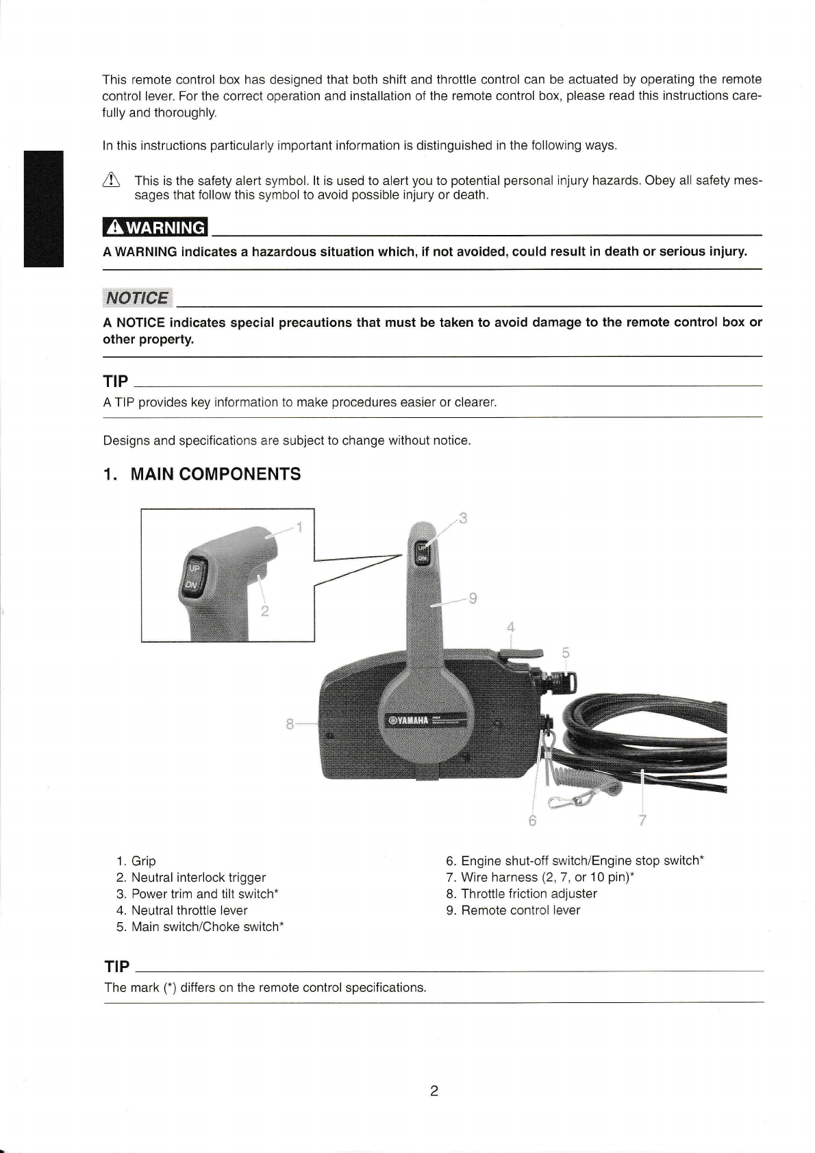
4. REMOTE CONTROL BOX
POSITIONING AND REMOTE
CONTROL CABLE LENGTH
lncorrect selection or installation of a remote
control box may reeuE in sudden and unexpect-
ed loss of eonüol, thus resulting in a serious ac-
cident. Please consutt yourYamaha dealer-
(1) Remote control box position
The remote control box should be set in a position
which it does not obstruct the operations of the re-
mote control lever and switches.
Make sure there is no obstruction on the path of the
remote control cables.
(2) Remote control cable length
Measure the distance from the "A" point (the center
of the remote control box) io the "C" point (the center
of the engine) through the "B" point (a corner of the
transom). Add 1 m (3 ft) length to make a loop in the
motor-well.
Position the remote control cables and check that
they are long enough. Connect ihe cables to the en-
gine and make sure they do not interfere with other
components when the steering is fully turned and
the engine is fulty tilted up.
Do not bend the 33C type (standard inner core)
remote eontro! cable to the 400 mm (16 in) or
less in diameter, and the 33HPC type (low-friction
inner core) remote control cable to the 300 mm
(12 in) or less in diameter.
Bending the cable sharper than this limit could
cause shorten the !ife span of the cable and
increase resistance to the movement of the re-
mote control lever.
1. Loop
INSTALLING THE REMOTE
CONTROL CABLES
Pinch the wire cover with your fingers and pull it
out to remove.
5.
1)
1. Wire cover
2) Remove the two screws, and remove the
panel (loweO.
L
back
3)
-^/
1'
Back panel (lower)
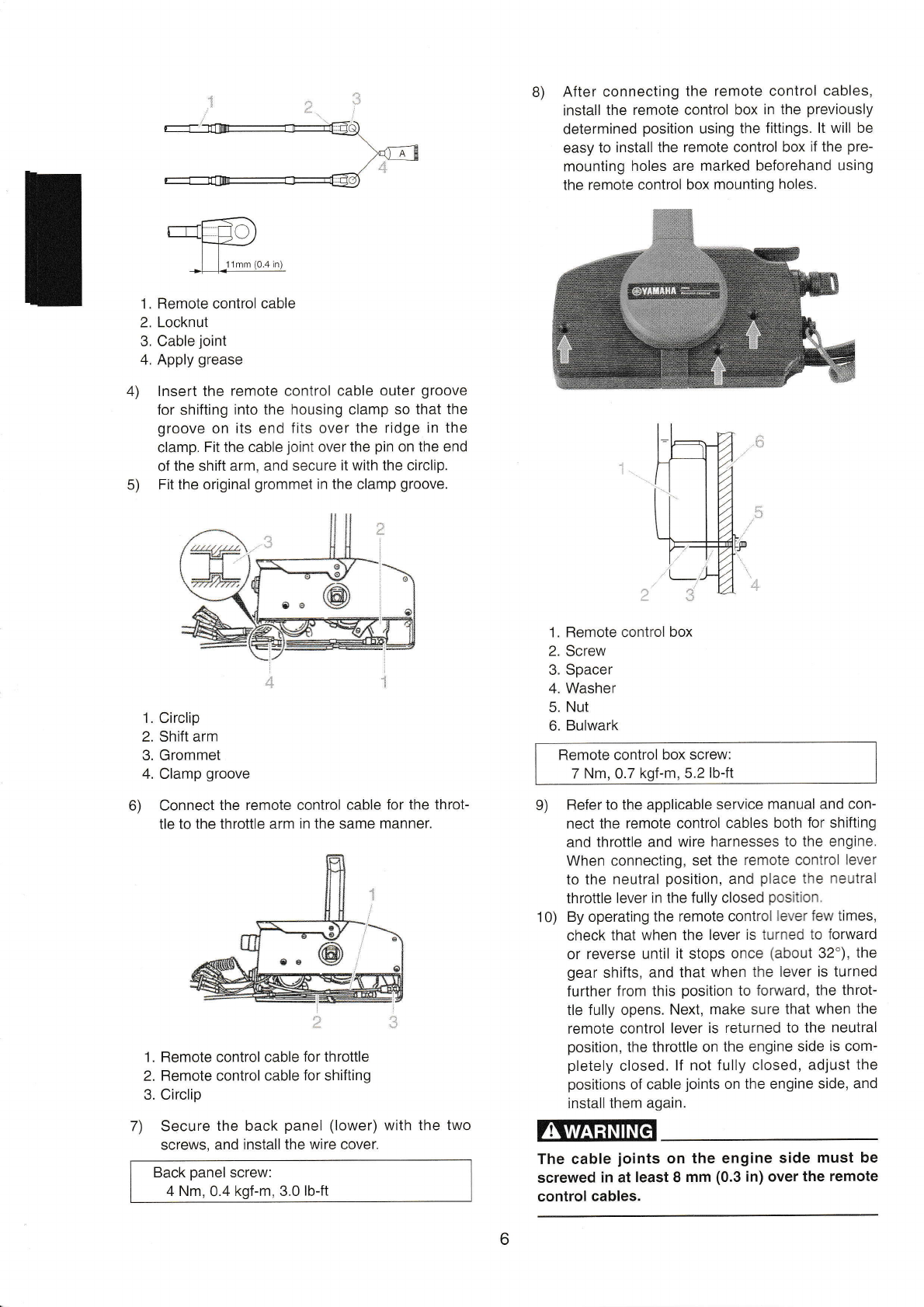
Screw in the cable joints about 11 mm (0.4 in)
over ihe ends of the remote control cables,
and tighten the locknuts. Before installing the
cable joints, apply the water-resistance grease
(Yamaha Grease A) to the holes in the cable
joints.