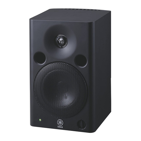
Yamaha MSP Series User manual

SERVICE MANUAL
SPECIFICATIONS(総合仕様)..................................................................... 3
DIMENSIONS(寸法図).............................................................................. 4
PANEL LAYOUT(パネルレイアウト)......................................................... 5
CIRCUIT BOARD LAYOUT(ユニットレイアウト).................................... 6
DISASSEMBLY PROCEDURES(分解手順)............................................... 7
CIRCUIT BOARDS(シート基板図)........................................................... 11
INSPECTIONS(検査)............................................................................... 13
BLOCK DIAGRAM(ブロックダイアグラム)............................................ 15
CIRCUIT DIAGRAM(回路図)................................................................... 16
PARTS LIST
■CONTENTS(目次)
PA 011843
Copyright (c) Yamaha Corporation. All rights reserved. 06.11
HAMAMATSU, JAPAN
このサービスマニュアルはエコパルプ
(ECF:無塩素系漂白パルプ)を使用しています。
200612-34650

MSP5 STUDIO
2
■WARNING
Components having special characteristics are marked and must be replaced with parts having specification equal to those originally
installed.
印の部品は、安全を維持するために重要な部品です。交換する場合は、安全のために必ず指定の部品をご使用ください。
IMPORTANT NOTICE
This manual has been provided for the use of authorized Yamaha Retailers and their service personnel. It has been assumed that basic service
procedures inherent to the industry, and more specifically Yamaha Products, are already known and understood by the users, and have
therefore not been restated.
WARNING: Failure to follow appropriate service and safety procedures when servicing this product may result in personal injury, destruc-
tion of expensive components and failure of the product to perform as specified. For these reasons, we advise all Yamaha
product owners that all service required should be performed by an authorized Yamaha Retailer or the appointed service
representative.
IMPORTANT: This presentation or sale of this manual to any individual or firm does not constitute authorization, certification, recognition of
any applicable technical capabilities, or establish a principal-agent relationship of any form.
The data provided is believed to be accurate and applicable to the unit(s) indicated on the cover. The research engineering, and service
departments of Yamaha are continually striving to improve Yamaha products. Modifications are, therefore, inevitable and changes in specifica-
tion are subject to change without notice or obligation to retrofit. Should any discrepancy appear to exist, please contact the distributor’s Service
Division.
WARNING: Static discharges can destroy expensive components. Discharge any static electricity your body may have accumulated by
grounding yourself to the ground bus in the unit (heavy gauge black wires connect to this bus).
IMPORTANT: Turn the unit OFF during disassembly and parts replacement. Recheck all work before you apply power to the unit.
WARNING: CHEMICAL CONTENT NOTICE!
The solder used in the production of this product contains LEAD. In addition, other electrical/electronic and/or plastic (Where applicable)
components may also contain traces of chemicals found by the California Health and Welfare Agency (and possibly other entities) to cause
cancer and/or birth defects or other reproductive harm.
DO NOT PLACE SOLDER, ELECTRICAL/ELECTRONIC OR PLASTIC COMPONENTS IN YOUR MOUTH FOR ANY REASON WHAT SO
EVER!
Avoid prolonged, unprotected contact between solder and your skin! When soldering, do not inhale solder fumes or expose eyes to solder/flux
vapor!
If you come in contact with solder or components located inside the enclosure of this product, wash your hands before handling food.
IMPORTANT NOTICE FOR THE UNITED KINGDOM
Connecting the Plug and Cord
WARNING: THIS APPARATUS MUST BE EARTHED
IMPORTANT. The wires in this mains lead are coloured in accordance with the following code:
GREEN-AND-YELLOW: EARTH
BLUE: NEUTRAL
BROWN: LIVE
As the colours of the wires in the mains lead of this apparatus may not correspond with the coloured markings identifying the terminals in your
plug, proceed as follows:
The wire which is coloured GREEN and YELLOW must be connected to the terminal in the plug which is marked by the letter E or by the safety
earth symbol or colored GREEN or colored GREEN and YELLOW.
The wire which is coloured BLUE must be connected to the terminal which is marked with the letter N or coloured BLACK.
The wire which is coloured BROWN must be connected to the terminal which is marked with the letter L or coloured RED.

MSP5 STUDIO
3
■SPECIFICATIONS(総合仕様)
* These specifications apply to rated power supplies of 120,
230 and 240 V.
* これらの規格値は定格電圧100V供給時に適用されます。
総合仕様
形式 ................バイ・アンプ2ウェイパワード・スピーカー
クロスオーバー周波数 ............................................... 2.5kHz
LF:24dB/oct、HF:24dB/oct
再生周波数帯域 ................................ 50Hz〜40kHz(-10dB)
最大出力音圧レベル ............................ 101dB、1monAxis
最大外形寸法(W×H×D)......................179x279x208mm
質量 ............................................................................... 7.9kg
防磁型 .............................................................................. Yes
スピーカー部
スピーカーユニット LF ...................... 12cmコーン(防磁型)
HF .................... 2.5cmドーム(防磁型)
エンクロージャー 方式 .................................... バスレフ型
材質 .................................................. PP
アンプ部
定格最大出力* ........................................................ LF:40W
THD=0.02%、RL=4Ω
HF:27W
THD=0.02%、RL=6Ω
S/N、IHF-Afilter ........................... ≧94dB、LEVEL=Max.
入力感度
XLR-3-31 .... +4dBu、LEVEL=Center
-6dBu、LEVEL=Max.
PHONE ...... -10dBu、LEVEL=Center
-20dBu、LEVEL=Max.
入力端子、インピーダンス
XLR-3-31(balanced)、10kΩ
PHONE(unbalanced)、10kΩ
コントロール レベルコントロール ......... 31Positions
DetenttypeVR
(Min=-∞Attenuation)
HIGHTRIM ....................+1.5/0/-1.5dB
at15kHz
LOWTRIM ................ +1.5/0/-1.5/-3dB
at60Hz
POWERswitch ....................... ON/OFF
インジケーター LED ............................緑色:PowerOn
赤:Clipping
消費電力 ......................................................................... 60W
電源コード
長さ ............................................................................... 2.5m
付属品
電源コード、ゴム脚(2個)
General Specifications
Type ...................................... Biamp 2-way Powered speaker
Crossover Frequency ................................................ 2.5 kHz
LF: 24 dB/oct, HF: 24 dB/oct
Overall Frequency Response .......... 50 Hz - 40 kHz (-10 dB)
Maximum Output Level .......................... 101 dB, 1 m on Axis
Dimensiones (W x H x D) ......................179 x 279 x 208 mm
(7-1/2” x 11” x 8-3/16”)
Weight ........................................................................... 7.9 kg
Magnetic Shielding ........................................................... Yes
Speaker section
Components LF ...................... 5” cone (Magnetic Shielding)
HF .................. 1.0” dome (Magnetic Shielding)
Enclosure Type ............................................... Bass-reflex
Material ....................................................... PP
Amplifier section
Output Power* .......................................................... LF: 40 W
THD = 0.02 %, RL = 4 Ω
HF: 27 W
THD = 0.02 %, RL = 6 Ω
S/N, IHF-A filter ................................ ≥94 dB, LEVEL = Max.
Input Sensitivity
XLR-3-31 ................. +4 dBu, LEVEL = Center
-6 dBu, LEVEL = Max.
PHONE................... -10 dBu, LEVEL = Center
-20 dBu, LEVEL = Max.
Input Connectors, Impedance
XLR-3-31 (balanced), 10 kΩ
PHONE (unbalanced), 10 kΩ
Controls LEVEL control .... 31 Positions Detent type VR
(Min = - ∞Attenuation)
HIGH TRIM ............... +1.5/0/-1.5 dB at 15 kHz
LOW TRIM.............. +1.5/0/-1.5/-3 dB at 60 Hz
POWER switch ................................... ON/OFF
Indicators LED ...................................... Green: Power On
Red: Clipping
Power Consumption....................................................... 60 W
AC code
Length ........................................................................... 2.5 m
Accessories
AC cord x 1, Non-skid pads x 2

MSP5 STUDIO
4
179 (7-1/16")
110*
20*
279 (11")30 60
208 (8-3/16")
*Non-skid pad positions.(ゴム脚貼付位置)
(For mounting bracket
(ブラケット用)
)
2-M5
■DIMENSIONS(寸法図)
Unit: mm
単位:mm

MSP5 STUDIO
5
3
47
5
6
1 2
■PANEL LAYOUT(パネルレイアウト)
• Front Panel
(フロントパネル)
• Rear Panel(リアパネル)
1
2
3
4
5
6
7
POWER indicator
LEVEL control
POWER switch
AC IN connector
LOW TRIM switch
HIGH TRIM switch
INPUT 1/2 connector
1
2
3
4
5
6
7
POWERインジケーター
LEVELコントロール
POWERスイッチ
ACIN端子
LOWTRIMスイッチ
HIGHTRIMスイッチ
INPUT端子

MSP5 STUDIO
6
■CIRCUIT BOARD LAYOUT(ユニットレイアウト)
Power
Transformer
(電源トランス)
AMP
LED
VOLUME
INPUT
Tweeter
(ツイータ)
Woofer
(ウーファー)

MSP5 STUDIO
7
Guide
(ガイド)
Cut
(切り込み)
Metal Grille
(メタルグリル)
■DISASSEMBLY PROCEDURE(分解手順)
1. Woofer (Time required: About 1 minute)
1-1 Remove the metal grille. (Fig. 1)
1-2 Remove the four (4) hexagonal socket screws marked
[200]. The woofer can then be removed. (Fig. 1)
Fig. 1(図1) Fig. 2(図2)
1. ウーファー(所要時間:約1分)
1-1 メタルグリルを外します。(図1)
1-2 [200]の6角穴付ネジ4本を外し、ウーファーを外しま
す。(図1)
[200]
Woofer
(ウーファー)
Metal Grille
(メタルグリル)
[200]
Rear Panel Assembly
(リアパネルAss'y)
[210]
[210] [210]
[200]: Hexagonal Socket Tapping Screw-P 4x14 (WJ271000) 6角
穴付Pタイト
[210]: Bind Head Tapping Screw-P 5x25 (WJ286300) +バインドP
タイト
3. ツィータ(所要時間:約3分)
3-1 リアパネルAssyを外します。(2項参照)
3-2 [A]のネジ4本を外し、ツィータを外します。(図3)
※ 軽く手前に力を加えれば容易に外せます。
3. Tweeter (Time required: About 3 minutes)
3-1 Remove the rear panel assembly. (See procedure 2)
3-2 Remove the four (4) screws marked [A]. The tweeter
can then be removed. (Fig. 3)
* Pull the tweeter lightly away from the cabinet to re-
move it.
[ A ][ A ]
Tweeter
(ツイータ)
Rear view
2. Rear panel Assembly
(Time required: About 2 minutes)
2-1 Remove the ten (10) screws marked [210].
The rear panel assembly can then be removed. (Fig. 2)
2. リアパネルAssy(所要時間:約2分)
2-1 [210]のネジ10本を外し、リアパネルAssyを外しま
す。(図2)
※ メタルグリルの取付時には、切り込
みをガイドに合わせてください。
* When installing the metal grille, align
the cut with the guide.
Fig. 3(図3)

MSP5 STUDIO
8
4. Power Transformer
(Time required: About 3 minutes)
4-1 Remove the rear panel assembly. (See procedure 2)
4-2 Remove the three (3) screws marked [B] and screw
marked [C].The power transformer can then be removed.
(Fig. 4)
4. 電源トランス(所要時間:約3分)
4-1 リアパネルAssyを外します。(2項参照)
4-2 [B]のネジ3本、[C]のネジを外し、電源トランスを外
します。(図4)
Power Transformer
(電源トランス)
[C]
[B]
[B]
Fig. 4(図4)
[ E ]
[ D ]
[ D ]
Transformer Bracket
(トランス金具)
[G]
[G]
[G]
[F]
Bracket Shield
(シールド金具)
INPUT
AMP
Fig. 5(図5)
Fig. 6(図6)
5 AMPシート、INPUTシート
(所要時間:各約5分)
5-1 リアパネルAssyを外します。(2項参照)
5-2 [B]のネジ3本と[C]のネジを外し、電源トランスを外
します。(図4)
5-3 [D]のネジ3本と[E]のネジを外し、トランス金具を外
します。(図5)
5-4 AMPシート:
5-4-1 [F]のネジ2本と[G]のネジ4本を外し、AMPシートを外
します。(図6)
5 AMP Circuit Board, INPUT Circuit Board
(Time required: About 5 minutes each)
5-1 Remove the rear panel assembly. (See procedure 2)
5-2 Remove the three (3) screws marked [B] and screw
marked [C].The power transformer can then be removed.
(Fig. 4)
5-3 Remove the three (3) screws marked [D] and screw
marked [E]. The transformer bracket can then be re-
moved. (Fig. 5)
5-4 AMP Circuit Board:
5-4-1 Remove the two (2) screws marked [F] and the four (4)
screws marked [G]. The AMP circuit board can then be
removed. (Fig. 6)

MSP5 STUDIO
9
[220A]
[220A]
[220B]
[220A]
[230], [240]
[230]
[220B]
[240]
[220A/B]: Bonding Tapping Screw-B 3x8 (WJ286400) +ボンディ
ングBタイト
[230]: Hexagonal Nut M12 (WJ285500) +6角ナット
[240]: Washer 12x16x0.6 (WJ286200) +ワッシャー
Fig. 7(図7)
6. VOLUME Circuit Board
(Time required: about 2 minutes)
6-1 Remove the rear panel assembly. (See procedure 2)
6-2 Remove the knob marked [50] and the nut.
The VOLUME circuit board can then be removed.
(Fig. 8)
7. LED Circuit Board
(Time required: about 2 minutes)
7-1 Remove the rear panel assembly. (See procedure 2)
7-2 Remove the two (2) screws marked [H]. The LED circuit
board can then be removed. (Fig. 9)
6. VOLUMEシート(所要時間:約2分)
6-1 リアパネルAssyを外します。(2項参照)
6-2 [50]のツマミとナットを外し、ボリュームシートを外
します。(図8)
7. LEDシート(所要時間:約2分)
7-1 リアパネルAssyを外します。(2項参照)
7-2 [H]のネジ2本を外し、LEDシートを外します。(図9)
Nut
(ナット)
[50]
[50]
Fig. 8(図8)
[50]: Knob Volume (WJ269800) ボリュームノブ
5-5 INPUTシート:
5-5-1 [220A]のネジ4本を外し、シールド金具を外します。
(図7)
5-5-2 [220B]のネジ3本、[230]の6角ナットおよび[240]の
ワッシャ−を外し、INPUTシートを外します。(図7)
5-5 INPUT Circuit Board:
5-5-1 Remove the four (4) screws marked [220A].The bracket
shield can then be removed. (Fig. 7)
5-5-2 Remove the three (3) screws marked [220B], the nut
marked [230], and the washer marked [240]. The IN-
PUT circuit board can then be removed. (Fig. 7)
[H]
LED
VOLUME
Fig. 9(図9)

MSP5 STUDIO
10
8. Heat Sink (Time required: about 6 minute)
8-1 Remove the rear panel assembly. (See procedure 2)
8-2 Remove the power transformer and the bracket trans.
(See procedure 5-2, 5-3)
8-3 Remove the AMP circuit board. (See procedure 5-4)
8-4 Remove the seven (7) screws marked [I] and screw
marked [J]. The heat sink can then be removed.
(Fig. 10)
* Pull the heat sink lightly away from the rear panel to
remove it.
9. Power Switch
(Time required: About 2 minutes)
9-1 Remove the rear panel assembly. (See procedure 2)
9-2 Press the claw to remove the power switch. (Fig. 11)
8. ヒートシンク(所要時間:約6分)
8-1 リアパネルAssyを外します。(2項参照)
8-2 電源トランスとトランス金具を外します。
(5-2、5-3項参照)
8-3 AMPシートを外します。(5-4項参照)
8-4 [I]のネジ7本と[J]のネジを外し、ヒートシンクを外し
ます。(図10)
※ 軽く力を加えれば、容易にヒートシンクを外すこと
ができます。
9. POWERスイッチ(所要時間:約2分)
9-1 リアパネルAssyを外します。(2項参照)
9-2 ツメを押さえながらPOWERスイッチを外します。
(図11)
[J]
[I]
[I]
[I]
[I] Heat sink
(ヒートシンク)
Power Switch
(POWERスイッチ)
Claw
(ツメ)
Fig. 10(図10)
Fig. 11(図11)

MSP5 STUDIO
11
■CIRCUIT BOARDS(シート基板図)
WOOFER
TWEETER
to Power Transformer
to INPUT CN106A
to LED CN206
HIGH TRIM
INPUT
21
(-20~-10dBu)(-6~+4dBu) dB
-1.5
0
+1.5
LOW TRIM
dB
-3
-1.5
0
+1.5
to Power Transformer
to Power SW
to VOLUME CN108
AC INLET
•AMP Circuit Board
Component side(部品側)
Component side(部品側)
•INPUT Circuit Board

MSP5 STUDIO
12
•VOLUME Circuit Board •LED Circuit Board
Component side(部品側) Component side(部品側)
VOLUME
to INPUT CN103
to AMP CN201

MSP5 STUDIO
13
Measuring Voltage [測定電圧] AC100 V, 50/60 Hz (J)
AC120 V, 60 Hz (U, C, T)
AC240 V, 50 Hz (A)
AC230 V, 50 Hz (B)
AC230 V, 50 Hz (H)
AC220 V, 60 Hz (K)
AC230 V, 50 Hz (O)
Load [負荷] LF 4 Ω
HF 6 Ω
LEVEL VR [レベル VR] MAX.
Tone-control SW [トーンコントロール SW] HIGH SW, LOW SW: 0 position.
1. Electric performance(電気性能)
INPUT CONDITIONS
(入力条件)
Output Power
(定格出力)
GAIN
(利得)
Frequency Response
(周波数特性)
Tone-control
Characteristic
(トーンコントロール特性)
Noise Level
Residual Noise
(残留雑音)
MAX. Noise
DC Voltage
ITEM
(項目)
OUTPUT CONDITIONS
(出力条件)
20 Hz
60 Hz
400 Hz
2 KHz
4 KHz
20 KHz
LF: 24.2 dBu OUTPUT
HF: 24.2 dBu OUTPUT
LF SP-OUT
< 0.02 %
< 0.02 %
24.2 dBu ±2 dB
24.2 dBu ±2 dB
24.2 dBu ±2 dB
24.2 dBu ±2 dB
-15 ±2 dB
-6 ±1 dB
+1 ±0.7 dB
0 ±0.5 dB
-19 ±3 dB
-14.5 ±2 dB
-3.7 ±1.2 dB
+1.5 ±1 dB
-3 ±1.5 dB
-1.5 ±1 dB
+1.5 ±1 dB
-1.5 ±1 dB
+1.5 ±1 dB
< -70 dBu
< -70 dBu
< -60 dBu
< ±50 mV
LIMIT
(限界値)
REF: LF OUTPUT
1 KHz 1 W (WF)
REF: LF OUTPUT
1 KHz 1 W (WF)
REF: LF OUTPUT
1 KHz 1 W (WF)
REF: LF OUTPUT
1 KHz 1 W (WF)
REF: LF OUTPUT
1 KHz 1 W (WF)
REF: LF OUTPUT
1 KHz 1 W (WF)
REF: LF OUTPUT
LOW SW: 0
REF: HF OUTPUT
HIGH SW: 0
LF SP-OUT
DIN AUDIO Filter
HF SP-OUT
DIN AUDIO Filter
LF SP-OUT
DIN AUDIO Filter
HF SP-OUT
LF-SP OUT
INPUT1 400 Hz
INPUT1 10 KHz
INPUT1 -6 dBu 400 Hz
VR: MAX
INPUT1 +4 dBu 400 Hz
VR: CENTER
INPUT2 -20 dBu 400 Hz
VR: MAX
INPUT2 -10 dBu 400 Hz
VR: CENTER
INPUT1
HIGH SW: 0
LOW SW: 0
LOW = -3
REF: 60 Hz
LOW = -1.5
REF: 60 Hz
LOW = +1.5
REF: 60 Hz
HIGH = -1.5
REF: 15 KHz
HIGH = +1.5
REF: 15 KHz
LEVEL VR = MIN.
HIGH SW: 0
LOW SW: 0
LEVEL VR = MAX.
HIGH SW: 0
LOW SW: 0
No Signal
No.
1
2
3
4
5
6
7
■INSPECTIONS(検査)
LF SP-OUT
LF SP-OUT
LF SP-OUT
LF SP-OUT
HF SP-OUT
LF SP-OUT
HF SP-OUT
HF SP-OUT
(NOTE): 0 dBu = 0.775 V

MSP5 STUDIO
14
パワースイッチをON/OFFにした時のリレーの動作時間
と、SP端子間に現れるポップノイズはLF、HF共に下表の
範囲であることを確認します。
2. Muting operation(Muting動作)
3-1 Q201のベースに2.2kΩを介してDC+3Vを印加した時リ
レーが即刻OFFになることを確認します。
3-2 Q202のベースに2.2kΩを介してDC-3Vを印加した時リ
レーが即刻OFFになることを確認します。
3. Protection circuit operation(保護回路動作)
4. Clipping level indication(クリップレベル表示)
400Hzを入力し、LF-SPOUTの出力レベルが27dBuとな
るようにしたとき、LEDが緑から赤色に変化することを
確認します。
POWER SWITCH
Non-signal
(無信号)
INPUT Relay operation time
(リレー動作時間)
3.0 ±1.5 sec
1.0 +1.5/-1.0 sec
≤0.1 Vp-p
≤0.1 Vp-p
Noise output voltage(ノイズ出力電圧)
LF, HF SP-OUT
OFF →ON
ON →OFF
Turn ON or OFF the power switch and check the relay
operation time and the pop noise obtained at SP terminal
is within the range specified in the following table.
3-1 Input DC +3 V to the base terminal of Q201 through the
2.2 kΩresistance and check the relay turns off at once.
3-2 Input DC -3 V to the base terminal of Q202 through the
2.2 kΩresistance and check the relay turns off at once.
Input the 400 Hz signal to the input terminal and check
the color of the power indicator is changed from green to
red when the output level obtained at LF-SP OUT termi-
nal is 27 dBu.
5. Stability(安定度)
5-1 Vary the power supply voltage ±10 % and check the oscil-
lation or the like does not occur.
5-2 Connect the following capacitors to the output terminal
and check the oscillation or the like does not occur.
5-1 電源電圧を±10%変化させたとき、発振等を生じないこと
を確認します。
5-2 スピーカー端子に下記容量負荷を接続し、発振等を生じ
ないことを確認します。
1
47 p
Capacity
容量
2
100 p
3
330 p
4
470 p
5
1000 p
6
3300 p
7
4700 p
8
0.01 µ
9
0.033 µ
0
0.047 µ
6. Factory Settings(出荷時の設定)
POWER : OFF
LOW TRIM : 0
HIGH TRIM : 0
LEVEL control : MIN.

MSP5 STUDIO
MSP5 STUDIO
15
MSP5 STUDIO
ABCDEFGH
2
3
4
5
6
7
1
+15V D51,52
RED GREEN
Q52-54
A
IC205-2/2 IC205-1/2
POWER AMP
+Vcc
JK101 +15V -15V -15V +15V
D91
TWEETER
YE
BL
125
6
TRIM IC202
-1/2
7
821 31 75
8
4IC201-1/2
3-Vcc
IC101-2/2 IC101-1/2
HIGHLOW
IC102-1/2 IC102-2/2
WOOFER
-15V
IC201-2/2
JK102 +15V
-15V
+15V
F101C232
POWER
AC INLETAC CORD
POWER AMP
-Vcc +Vcc +15V -15V
PROTECTION
POWER TRANSFORMER
(電源トランス)
VR101
*S
*S: soldered
*S
*S
LEVEL
CN105 (3P)
+15V
D202
D201 R213 RLY1
R217
IC204
IC203
DB201
-15V
CN108 (3P)
CN103 (3P)
4
CN104 (4P)
CN101 (3P)
IC202
-2/2
CN206 (3P)
CN201 (3P)CN106B (4P)
CN106A (4P)
CN207 (4P)
CN205 (3P)
7
8
-15V
4
1
1
2
5
4
53
15
13
14
16
2
LED
DRIVE
A
B
C
+
++
+
–
+
–
–
+
–
+
–
BK
RE
–
+
+
–
-15V
5
4
7
LPF
+15V
3
8
1
HPF
B
C
Q201-203
AMP
AMP
VOLUME LED
INPUT 5/5
2/5 4/5 1/5
3/5
■BLOCK DIAGRAM(ブロックダイアグラム)

MSP5 STUDIO
16
MSP5 STUDIO
MSP5 STUDIO
ABCDEFGHI
1
2
3
4
5
6
Note : See parts list for details of circuit board component parts.
注 :シートの部品詳細はパーツリストを御参照ください。
N.M : Not installed(実装しません)
(C)
:
Ceramic Capacitor
(セラミックコンデンサー)
:
Electrolytic Capacitor
(ケミカルコンデンサー)
(m)
:
Polyester Film Capacitor
(ポリエステルフィルムコンデンサー)
(K)
:MetalFilmResistor
(金属被膜抵抗)
ZA1F9A00102
Components having special characteristics are marked and must be
replaced with parts having specification equal to those originally installed.
印の部品は、安全を維持するために重要な部品です。交換する場合は、安全の
ために必ず指定の部品をご使用ください。
WARNING (注意)
J, U, T : 1.6 A
H, B, A, K, O : 630 mA
AC INLET
OP AMP
POWER AMP
REGULATOR +15V
REGULATOR -15V
OP AMP
OP AMP
OP AMP OP AMP
POWER TRANSFOMER
VH 4P
Jumper
WOOFFER
4Ω
TWEETR
6Ω
LED
VOLUME
AMP
AMP
INPUT
VH 3P
■CIRCUIT DIAGRAM(回路図)

PARTS LIST
OVERALL ASSEMBLY(総組立)............................................................ 2
ELECTRICAL PARTS(電気部品)........................................................... 4
■CONTENTS(目次)
Notes: DESTINATION ABBREVIATIONS
A : Australian model
B : British model
C : Canadian model
D : German model
E : European model
F : French model
H : North European model
I : Indonesian model
J : Japanese model
K : Korean model
M : South African model
O : Chinese model
Q : South-east Asia model
T : Taiwan model
U : U.S.A. model
V : General export model (110V)
W: General export model (220V)
N,X: General export model
Y : Export model
■WARNING(注意)
Components having special characteristics are marked and must be replaced with parts having
specification equal to those originally installed.
印の部品は、安全を維持するために重要な部品です。交換する場合は、安全のために必ず指定の部品
をご使用ください。
• The numbers “QTY” show quantities for each unit.
• The parts with “--” in “PART NO.” are not available as spare parts.
• This mark “ } ” in the REMARKS column means these parts are interchangeable.
• The second letter of the shaded ( ) part number is O, not zero.
• The second letter of the shaded ( ) part number is I, not one.
•部品価格ランクは、変更になることがあります。
•QTY 欄に記されている数字は、各ユニット当たりの使用個数です。
•PARTNO. が--の部分は、サービス用部品として準備されておりません。
•REMARKS 欄の「}」マークの部品は、併用部品です。
•網掛けの付いた PARTNO. の 2 番目の文字は「ゼロ」ではなく、「オー」です。
•網掛けの付いた PARTNO. の 2 番目の文字は「イチ」ではなく、「アイ」です。
MSP5 STUDIO

MSP5 STUDIO
2
■OVERALL ASSEMBLY(総組立)
Non-skid pad(ゴム脚)
10a
10
10b
10c
10d
10e
20 50
30
40
40a
40b
Accessories of VOLUME
(VOLUME付属品)
Apply bond hear
(接着剤)
JK101JK102
100
110
120
130
140
150
160
170
180
200
210
210
210
220
220
230
240
250
260
270
280 290
300
270
280
290
300

MSP5 STUDIO
3
RANKQTYREMARKSDESCRIPTION 部品名REF NO. PART N O.
: New Parts RANK: Japan only
OVERALL ASSEMBLY MSP5 STUDIO
Overall Assembly MSP5 STUDIO J J
Overall Assembly MSP5 STUDIO U U
Overall Assembly MSP5 STUDIO H H
Overall Assembly MSP5 STUDIO B B
Overall Assembly MSP5 STUDIO A A
Overall Assembly MSP5 STUDIO K K
Overall Assembly MSP5 STUDIO T T
Overall Assembly MSP5 STUDIO O O
*10 Enclosure Assembly
*10a Cabinet 437793
*10b Badge 447802
*10c Tape Sheet 446786
*10d Bolt A274A0-5 433645 2
*10e Nut M8 CR3 412967 2
20 Speaker 12cm 4 ohm WOOFER 437508 11
30 Speaker 2.4cm 6 ohm TWEETER 443311 11
*40 Metal Grille Assembly
*40a Metal Grille 448349
*40b Cushion 10x95x1 447573 4
*50 Knob Volume LEVEL VOLUME 439134
*100 Rear Panel 449567
*110 Heat Sink J J 453791
*110 Heat Sink U/C U 453792
*110 Heat Sink B,H H,B 453794
*110 Heat Sink A A 453793
*110 Heat Sink K K 453798
*110 Heat Sink TT T 453802
*110 Heat Sink CHN O 453801
s*120 Power Transformer J J 420235
s*120 Power Transformer U/C,TT U,T 420236
s*120 Power Transformer B,H,CHN H,B,O 420237
s*120 Power Transformer A A 420238
s*120 Power Transformer K K 420239
*130 Circuit Board AMP (MAIN1/5,3/5)
*140 Circuit Board INPUT (MAIN5/5) J,U,T
*140 Circuit Board INPUT (MAIN5/5) H,B,A,K,O
*150 Circuit Board LED (MAIN4/5)
*160 Circuit Board VOLUME(MAIN2/5)
s170 Power Switch SDDJE30100 POWER ON/OFF 381326 06
s*180 AC Inlet SS-120-2.0A-4.0A 446341
*200 Hex.Socket Tapping Screw-P 4x14 NI-BL for WOOFER 423333 4
*210 Bind Head Tapping Screw-P 5x25 NI-BL for REAR PANEL 422354 10
*220 Bonding Tapping Screw-B 3x8 NI-BL for CIRCUIT BOARD 414198 7
*230 Hexagonal Nut M12 NI-BL for TRS CONNECTOR 421223
*240 Washer 12x16x0.6 for TRS CONNECTOR 417370
*250 Switch Cover 381494
*260 Switch Cover 381495
*270 Cushion for XLR CONNECTOR 354855
*280 Cushion for XRS CONNECTOR 356440
*290 Cushion for TRS CONNECTOR 354853
*300 Cushion for TRS CONNECTOR 354854
ACCESSORIES MSP5 STUDIO
sAC Cord J J 414427 08
sAC Cord U/C U 369532 08
sAC Cord H,A,K H,A,K 417976 08
sAC Cord B B 417977 12
sAC Cord TT T 444018
sAC Cord CHN O 414426 12
*Non-skid Pad A1D5A0 381493 2
WJ281200
WJ280100
WJ279900
WJ281300
WJ286000
WJ285600
XU973A0R
XU974A0R
WJ371900
WJ269900
WJ280000
WJ269800
WJ275900
WJ276100
WJ276200
WJ276500
WJ276800
WJ276700
WJ276400
WJ276600
WJ270000
WJ270100
WJ270200
WJ270400
WJ270300
WJ269200
WJ269300
WJ269600
WJ269500
WJ269400
WG263400
WJ279800
WJ271000
WJ286300
WJ286400
WJ285500
WJ286200
WJ371000
WJ371100
WJ371300
WJ371400
WJ371500
WJ371600
WG261700
WG261800
WG262000
WH221600
WH667300
WG262200
WJ370700
総組立
総組立
総組立
総組立
総組立
総組立
総組立
総組立
総組立
エンクロージャAssy
キャビネット
バッジ
テープシート
ボルト
ナット
スピーカ
スピーカ
メタルグリルAssy
メタルグリル
クッション
ボリュームノブ
リアパネル
ヒートシンク
ヒートシンク
ヒートシンク
ヒートシンク
ヒートシンク
ヒートシンク
ヒートシンク
電源トランス
電源トランス
電源トランス
電源トランス
電源トランス
AMPシート
INPUTシート
INPUTシート
LEDシート
VOLUMEシート
パワースイッチ
ACインレット
六角穴付Pタイト
+バインドPタイト
+ボンディングBタイト
六角ナット
ワッシャー
SWカバー
SWカバー
クッション
クッション
クッション
クッション
付属品
電源コード
電源コード
電源コード
電源コード
電源コード
電源コード
ゴム脚

MSP5 STUDIO
4
■ELECTRICAL PARTS(電気部品)
RANKQTYREMARKSDESCRIPTION 部品名REF NO. PART N O.
: New Parts RANK: Japan only
ELECTRICAL PARTS MSP5 STUDIO
*Circuit Board AMP (MAIN 1/5,3/5) (WJ26900,WJ26970)
(6482A-30_1/5,3/5)
*Circuit Board INPUT (MAIN 5/5) J,U,T (WJ26900)
(6482C-30_5/5)
*Circuit Board INPUT (MAIN 5/5) H,B,A,K,O (WJ26970)
(6482C-30_5/5)
*Circuit Board LED (MAIN 4/5) (WJ26900,WJ26970)
(6482E-30_4/5)
*Circuit Board VOLUME(MAIN 2/5) (WJ26900,WJ26970)
(6482D-30_2/5)
*Circuit Board AMP (WJ26900,WJ26970)
(6482A-30_1/5,3/5)
*IC202 IC STK-401-090-E POWER 381255
*Circuit Board INPUT J,U,T (WJ26900)
(6482C-30_5/5)
*Circuit Board INPUT H,B,A,K,O (WJ26970)
(6482C-30_5/5)
sF101 Fuse T1.6A 250V J,U,T 331109 02
s*F101 Fuse T630mA 250V H,B,A,K,O 085108
*JK101 XLR Connector NC3FAH1-0 INPUT1 381261
*JK102 TRS Connector HTJ-064-11I INPUT2 381260
*Circuit Board LED (WJ26900,WJ26970)
(6482E-30_4/5)
*Circuit Board VOLUME (WJ26900,WJ26970)
(6482D-30_2/5)
*VR101 Rotary Variable Resistor A20k LEVEL VOLUME 443239
Speaker 12cm 4 ohm WOOFER 437508 11
Speaker 2.4cm 6 ohm TWEETER 443311 11
s*Power Transformer J J 420235
s*Power Transformer U/C,TT U,T 420236
s*Power Transformer B,H,CHN H,B,O 420237
s*Power Transformer A A 420238
s*Power Transformer K K 420239
sPower Switch SDDJE30100 POWER ON/OFF 381326 06
sAC Cord J J 414427 08
sAC Cord U/C U 369532 08
sAC Cord H,A,K H,A,K 417976 08
sAC Cord B B 417977 12
sAC Cord TT T 444018
sAC Cord CHN O 414426 12
WJ269200
WJ269300
WJ269600
WJ269500
WJ269400
WJ269200
X8344A00
WJ269300
WJ269600
WG275900
WJ270500
WJ270600
WJ270700
WJ269500
WJ269400
WJ270800
XU973A0R
XU974A0R
WJ270000
WJ270100
WJ270200
WJ270400
WJ270300
WG263400
WG261700
WG261800
WG262000
WH221600
WH667300
WG262200
電気部品
AMPシート
INPUTシート
INPUTシート
LEDシート
VOLUMEシート
AMPシート
IC
INPUTシート
INPUTシート
ヒューズ
ヒューズ
XLRコネクタ
TRSコネクタ
LEDシート
VOLUMEシート
ロータリーVR
スピーカ
スピーカ
電源トランス
電源トランス
電源トランス
電源トランス
電源トランス
パワースイッチ
電源コード
電源コード
電源コード
電源コード
電源コード
電源コード
This manual suits for next models
1
Table of contents
Other Yamaha Speakers manuals

Yamaha
Yamaha TRS-MS02 User manual

Yamaha
Yamaha PJP-50USB User manual

Yamaha
Yamaha NS-B901 User manual

Yamaha
Yamaha DXR Series User manual

Yamaha
Yamaha YST-MS50 User manual

Yamaha
Yamaha PJP-20UR User manual

Yamaha
Yamaha MS202II User manual

Yamaha
Yamaha SPS-10MM User manual

Yamaha
Yamaha MSR250 User manual

Yamaha
Yamaha DXR8 Setup guide

Yamaha
Yamaha STAGEPAS 150M User manual

Yamaha
Yamaha A4115H User manual

Yamaha
Yamaha NS-ICS600 User manual

Yamaha
Yamaha PSG-01S User manual

Yamaha
Yamaha VXC4 User manual

Yamaha
Yamaha NS-PB120 User manual

Yamaha
Yamaha MSR400 User manual

Yamaha
Yamaha MS 100DR User manual

Yamaha
Yamaha HS8S User manual

Yamaha
Yamaha NS-BP401 User manual