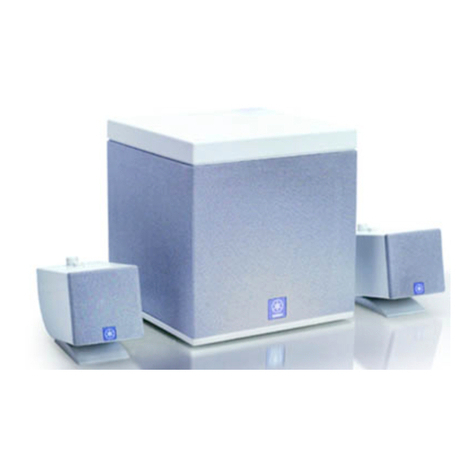
Yamaha NX-U10 - Speaker Sys User manual

P.O.Box 1, Hamamatsu, Japan
NX-U10
IC DATA ................................................................. 12–14
BLOCK DIAGRAM....................................................... 15
PRINTED CIRCUIT BOARDS ............................... 16–17
PIN CONNECTION DIAGRAMS ................................. 18
SCHEMATIC DIAGRAM .............................................. 19
REPLACEMENT PARTS LIST.............................. 21–25
101039
■CONTENTS
TO SERVICE PERSONNEL .......................................... 2
FRONT PANEL .............................................................. 3
REAR PANELS .............................................................. 3
SPECIFICATIONS / 参考仕様 ................................... 4–5
INTERNAL VIEW ........................................................... 5
DISASSEMBLY PROCEDURES / 分解手順 ............. 6–7
TROUBLESHOOTING / トラブルシューティング ..... 8–11
SERVICE MANUAL
MULTIMEDIA SPEAKER
NX-U10
'07.01
IMPORTANT NOTICE
This manual has been provided for the use of authorized YAMAHA Retailers and their service personnel.
It has been assumed that basic service procedures inherent to the industry, and more specifically YAMAHA Products, are
already known and understood by the users, and have therefore not been restated.
WARNING: Failure to follow appropriate service and safety procedures when servicing this product may result in per-
sonal injury, destruction of expensive components, and failure of the product to perform as specified. For
these reasons, we advise all YAMAHA product owners that any service required should be performed by
an authorized YAMAHA Retailer or the appointed service representative.
IMPORTANT: The presentation or sale of this manual to any individual or firm does not constitute authorization, certifica-
tion or recognition of any applicable technical capabilities, or establish a principle-agent relationship of
any form.
The data provided is believed to be accurate and applicable to the unit(s) indicated on the cover. The research, engineering,
and service departments of YAMAHA are continually striving to improve YAMAHA products. Modifications are, therefore,
inevitable and specifications are subject to change without notice or obligation to retrofit. Should any discrepancy appear to
exist, please contact the distributor's Service Division.
WARNING: Static discharges can destroy expensive components. Discharge any static electricity your body may have
accumulated by grounding yourself to the ground buss in the unit (heavy gauge black wires connect to this
buss).
IMPORTANT: Turn the unit OFF during disassembly and part replacement. Recheck all work before you apply power to
the unit.
2007 All rights reserved.
This manual is copyrighted by YAMAHA and may not be copied or
redistributed either in print or electronically without permission.

NX-U10
2
NX-U10
■TO SERVICE PERSONNEL
1. Critical Components Information
Components having special characteristics are marked s
and must be replaced with parts having specifications equal
to those originally installed.
2. Leakage Current Measurement (For 120V Models Only)
When service has been completed, it is imperative to verify
that all exposed conductive surfaces are properly insulated
from supply circuits.
●Meter impedance should be equivalent to 1500 ohms shunted
by 0.15µF.
●Leakage current must not exceed 0.5mA.
●Be sure to test for leakage with the AC plug in both polarities.
WALL
OUTLET
EQUIPMENT
UNDER TEST
AC LEAKAGE
TESTER OR
EQUIVALENT
INSULATING
TABLE
WARNING: CHEMICAL CONTENT NOTICE!
The solder used in the manufacturing process except soldering of the P.C.B. ass'y contains LEAD. In addition, other
electrical/electronic and /or plastic (where applicable) components may also contain traces of chemicals found by the
California Health and Welfare Agency (and possibly other entities) to cause cancer and/or birth defects or other reproductive
harm.
DO NOT PLACE SOLDER, ELECTRICAL/ELECTRONIC OR PLASTIC COMPONENTS IN YOUR MOUTH FOR ANY REA-
SON WHATSOEVER!
Avoid prolonged, unprotected contact between solder and your skin! When soldering, do not inhale solder fumes or expose
eyes to solder/flux vapor!
If you come in contact with solder or components located inside the enclosure of this product, wash your hands before
handling food.
本機に搭載されているすべての基板およびハンダ付けによる接合
部は無鉛ハンダでハンダ付けされています。
無鉛ハンダにはいくつかの種類がありますが、修理時には下記の
ような無鉛ハンダの使用を推奨します。
・Sn+Ag+Cu(錫+銀+銅)
・Sn+Cu(錫+銅)
・Sn+Zn+Bi(錫+亜鉛+ビスマス)
注意:
無鉛ハンダの融点温度は通常の鉛入りハンダに比べ30〜40℃
程度高くなっていますので、それぞれのハンダに合ったハンダ
ごてをご使用ください。
All of the P.C.B.s installed in this unit and solder joints are
soldered using the lead free solder.
Among some types of lead free solder currently available,
it is recommended to use one of the following types for the
repair work.
• Sn + Ag + Cu (tin + silver + copper)
• Sn + Cu (tin + copper)
• Sn + Zn + Bi (tin + zinc + bismuth)
Caution:
As the melting point temperature of the lead free solder
is about 30°C to 40°C (50°F to 70°F) higher than that of
the lead solder, be sure to use a soldering iron suitable
to each solder.
About lead free solder / 無鉛ハンダについて

NX-U10
3
NX-U10
■FRONT PANEL
■REAR PANELS
K modelT model
A, B, G, L models
Status indicator LED
V model
J model
L side view R side viewFront view
U model

NX-U10
4
NX-U10
• DIMENSIONS
Unit: mm (inch)
単位:mm(インチ)
■SPEAKER Section / スピーカー部
Type / 型式 YAMAHA SR-BASS technology /
YAMAHASR-BASS方式
Driver / スピーカーユニット
............................... 38 mm Titanium-cone full-range driver x 2,
Magnetic shielding type /
38mmチタン振動板フルレンジ×2、防磁型
Impedance / インピーダンス 6 ohms
■AMPLIFIER Section / アンプ部
Input / 入力端子
PORTABLE input .............................. 3.5 mm stereo mini jack /
3.5mmステレオミニジャック
USB input .............................................. USB terminal (mini B) /
USB端子(ミニB)
Dynamic Power / ダイナミックパワー
1 kHz, 6 ohms ................................................................6 W x 2
Maximum Instantaneous Power / 瞬間最大パワー
1 kHz, 6 ohms, 10 % THD ........................................... 10 W x 2
* Refers to the power that can be output for 100 ms continuously. /
連続して100ms出力可能なパワーです。
Input Sensitivity/Input Impedance / 入力感度/入力インピーダンス
PORTABLE input ...................................... 300 mV / 10 k-ohms
Maximum Input Signal / 最大許容入力
PORTABLE input .............................................................. 2.0 V
Frequency Response / 周波数特性 90 Hz to 20 kHz
■USB Section / USB部
PC / 対応機種
PC equipped with a USB port on which a Windows or Macintosh
operating system is installed. /
USBポートを備えたWindowsPCおよびMacintosh
OS
Windows PC Windows XP, 2000, Me, 98SE
Macintosh Mac OS 9.1 or later, Mac OS X 10.0 or later /
MacOS9.1以降、MacOSX10.1以降
■GENERAL / 総合
Power Supply / 電源電圧
USB bus power / USBバスパワー ........................ 5 V / 500 mA
USB/AC adapter / USB/ACアダプター
Input ............................................... AC100 to 240V, 50/60 Hz
Output ................................................................. 5 V / 500 mA
Battery / 乾電池 AAA/R03/UM-4 x 4 / 単4乾電池×4
* Battery life / 乾電池の寿命
3 hours as alkaline (Output : 10 mW + 10 mW) /
アルカリ乾電池使用時約3時間(10mW+10mW出力時)
Power Consumption / 消費電力
When the USB/AC adaptor is used / USB/ACアダプター使用時
Less than 5 W / 5W未満
Dimensions (W x H x D) / 外形寸法(幅×高さ×奥行き)
248 x 100 x 33 mm (9-3/4" x 3-15/16" x 1-5/16")
Weight / 質量 500 g (1 lb. 2 oz.)
Finish / 仕上げ Silver color
Accessories / 付属品
USB/AC adapter x 1, Battery holder x 1, USB cable (1 m, A-miniB)
x 1, 3.5 mm stereo mini plug cable (0.5 m) x 1, Carrying case x 1,
Nonskid pad (2pcs/set) x 1
Windows is a registered trademark of Microsoft Corporation in
the United States and/or other countries.
MicrosoftWindowsは米国MicrosoftCorporationの登録商標で
す。
Macintosh is a trademark of Apple Computer, Inc., registered in
the United States and other countries.
Macintoshは、米国AppleComputer,Inc.の登録商標です。
98 (3-7/8")
100 (3-15/16") 33
(1-5/16")
33
When using the stand.
(1-5/16")
248 (9-3/4")
60
(2-3/8")
* Specifications are subject to change without notice due
to product improvements.
※ 参考仕様および外観は予告なく変更されることがあります。
U .......... U.S.A. and Canada models
T .......... Chinese model K ...... Korean model
A .......... Australian model B ...... British model
G .......... European model L ....... Singapore model
V .......... Taiwan model J ....... Japanese model
“Swing Radiator BassTM”is a trademark of YAMAHA
CORPORATION.
SwingRadiatorBassTMはヤマハ株式会社の商標です。
■SPECIFICATIONS / 参考仕様

NX-U10
5
NX-U10
The current status of this unit /
本機の状態
This unit is on. /
電源がオンの状態。
This unit is off, or power supply is not connected. /
電源がオフ、または電源が接続されていない状態。
Limiter control has been activated due to excessive input. (Turn down the volume level until the LED stops flashing.) /
大音量の入力により、リミッターが作動している状態。(点灯状態に戻るまでボリュームを下げてください。)
The status indicator turns on or flashes to indicate the
status of this unit.
LED status /
ステータスインジケーター
On / 点灯
Off / 消灯
Flashing / 点滅
■INTERNAL VIEW
MAIN (3) P.C.B.
MAIN (1) P.C.B.
MAIN (5) P.C.B.
MAIN (4) P.C.B.
MAIN (6) P.C.B.
MAIN (2) P.C.B.
1
2
3
4
5
6
3
1
5
2
4
6
•About the Status Indicator (LED) / ステータスインジケーター(LED)について
本機の状態を表示するために、ステータスインジケーターが点
灯または点滅します。

NX-U10
6
NX-U10
Fig. 1
■DISASSEMBLY PROCEDURES / 分解手順
1
1
1
3
4
4
Front panel unit
フロントパネルユニット
Driver L
スピーカーユ ニットL
Driver R
スピーカーユニットR Side cover R
サイドカバーR
Side cover L
サイドカバーL
Ring
リング
Ring
リング
CB2
CB10
CB3
Note)
•After disassembling the unit or replacing any part, be
sure to input a signal (20 Hz to 20 kHz) from the POR-
TABLE terminal to make sure that the unit is free from
chattering or abnormal sound.
•The double coated adhesive tape and bush once re-
moved cannot be reused. Be sure to use a new
double coated adhesive tape and bush for replace-
ment.
注意)
・ 分解または部品交換後には、必ずPORTABLE端子から信号
(20Hzー20kHz)を入力し、本機のビリ付きまたは異音等
がないか確認してください。
・ 一度取り外した両面粘着テープおよびブッシュは、使用でき
ません。必ず、新しい両面粘着テープおよびブッシュに交換
してください。
1. Removal of Driver L/R
a. Remove 2 rings. (Fig. 1)
b. Remove side cover L. (Fig. 1)
c. Remove side cover R. (Fig. 1)
d. Remove 7 screws (1). (Fig. 1)
e. Open the rear cover, remove 3 screws (2). (Fig. 2)
f. Remove CB10. (Fig. 1)
g. Remove front panel unit. (Fig. 1)
h. Remove screw (3) and 4 screws (4). (Fig. 1)
i. Remove CB3 (driver L) and CB2 (driver R). (Fig. 1)
j. Remove the driver L/R. (Fig. 1)
1. スピーカーユニットL/Rの外し方
a. リング2個を外します。(Fig.1)
b. サイドカバーLを外します。(Fig.1)
c. サイドカバーRを外します。(Fig.1)
d. 1のネジ7本を外します。(Fig.1)
e. リアカバーを開けて、2のネジ3本を外します。(Fig.2)
f. CB10を外します。(Fig.1)
g. フロントパネルユニットを外します。(Fig.1)
h. 3のネジ1本、4のネジ4本を外します。(Fig.1)
i. CB3(スピーカーユニットL)、CB2(スピーカーユニットR)を
外します。(Fig.1)
j. スピーカーユニットL/Rを取り外します。(Fig.1)
Fig. 2
2
Rear cover
リアカバー

NX-U10
7
NX-U10
Fig. 3
2. Removal of MAIN (1) P.C.B.
a. Remove 4 screws (5). (Fig. 3)
b. Remove CB5, CB6, CB7, CB8 and CB9. (Fig. 3)
c. Remove MAIN (1) P.C.B. (Fig. 3)
3. Removal of MAIN (2), (3), (4) and (5) P.C.B.s
a. Remove 4 bush. (Fig. 3)
b. Remove cover shield (2), (3), (4) and (5). (Fig. 3)
c. Remove 4 screws (6). (Fig. 3)
d. Remove the MAIN (2), (3), (4) and (5) P.C.B.s. (Fig. 3)
2. MAIN(1)P.C.B.の外し方
a. 5のネジ4本を外します。(Fig.3)
b. CB5、CB6、CB7、CB8、CB9を外します。(Fig.3)
c. MAIN(1)P.C.B.を取り外します。(Fig.3)
3. MAIN(2)、(3)、(4)、(5)P.C.B.の外し方
a. ブッシュ4個を外します。(Fig.3)
b. カバーシールド(2)、(3)、(4)、(5)を外します。(Fig.3)
c. 6のネジ4本を外します。(Fig.3)
d. MAIN(2)、(3)、(4)、(5)P.C.B.を取り外します。(Fig.3)
5
56
6
6
6
Bush
ブッシュ
Cover shield (5)
カバーシールド(5)
Cover shield (4)
カバーシールド(4)
Bush
ブッシュ
Bush
ブッシュ
Cover shield (3)
カバーシールド(3)
Cover shield (2)
カバーシールド(2)
CB5
CB6
CB7
CB8
CB9
MAIN (2) P.C.B.
MAIN (1) P.C.B.
MAIN (3) P.C.B.
MAIN (4) P.C.B.
MAIN (5) P.C.B.
・ フロントパネルユニット交換時の注意
新しいフロントパネルユニットには、ホットメルトが塗られて
いません。
必ず、新しいフロントパネルユニットの下記4箇所にホットメ
ルトを塗ってから使用してください。
•Caution when replacing the front panel unit
The new front panel unit has no hot glue applied.
Be sure to apply hot glue to the new front panel unit at 4
locations as shown below before using it.
Front panel unit
フロントパネルユニット
Hook
フック
Hot glue is applied
ホットメルトを塗る

NX-U10
8
NX-U10
■TROUBLESHOOTING
•When the status indicator LED does not light up when "POWER" key is pressed.
•When no sound is produced.
NG NG
OK OK
PC/Macintosh and the main unit
are connected
with the USB cable.
Install
the USB/AC adapter
to the USB cable and connect it
to the AC outlet.
Does the LED turn
on ?
Disconnect
the USB cable from
the main unit and load the battery.
Does the LED turn
on ?
•Remove the USB/AC adapter,
connect the USB cable again and re-
check.
•Check USB DAC (IC2) and
peripheral circuit.
•Connect the cable to another PC/
Macintosh and check.
•Check the power circuit (IC1 and
Q15) and peripheral circuit.
(Is the power voltage +5V and +12V
correct ?)
•Check the power circuit (IC15 and
IC16) and peripheral circuit.
(Is the power voltage +5V, +12V and
+50V correct ?).
NG
OK
NG
OK
NG
OK OK
NG
PC/Macintosh and the main unit
are connected
with the USB cable.
Is the USB cable
connected properly?
•Recheck after reconnecting
the USB cable or after replacing
it with a new one.
Is
the audio device
of PC/Macintosh set to
“USB AUDIO DAC”? Also, is the
volume setting
muted ?
•Recheck settings on the PC/
Macintosh side.
Connect
the main unit and
PC/Macintosh or the
portable audio player to the
PORTABLE terminal with
3.5mm mini-plug cable.
Is the sound
produced ?
Is the power voltage (+5V and +12V)
correct ?
•Check the power circuit (IC1, IC15,
IC16, Q15) and peripheral circuit.
•Check USB DAC (IC2) and
peripheral circuit.
•
Check the audio circuit
(
IC5, IC9,
IC10 and IC12
)
and peripheral circuit.

NX-U10
9
NX-U10
NG
NG
OK
OK
The main unit and PC/Macintosh
or portable audio player
are connected
with 3.5mm mini-plug cable.
Is
3.5mm mini-plug cable
connected
properly?
•
Check the audio circuit
(
IC5, IC9,
IC10 and IC12
)
and peripheral circuit.
•Connect 3.5 mm mini-plug cable
again and recheck.
Also, replace 3.5mm mini-plug cable
and recheck.
Is
the power voltage
(+5V, +12V and +50V)
correct ?
•Check the power circuit (IC1, IC15,
IC16 and Q15) and peripheral circuit.

NX-U10
10
NX-U10
・POWERキーを押してステータスインジケーターLEDが点灯しない場合
・ 音が出ない場合
■トラブルシューティング
NG NG
OK OK
USBケーブルへ
USB/ACアダプターを取り付け、
ACコンセントに接続し
点灯するか?
本機に接続されている
USBケーブルを外し、
乾電池を入れて
点灯するか?
・ USB/ACアダプターを外しUSBケー
ブルを接続し直して再度確認する。
・ USBDAC(IC2)とその周辺回路を
確認する。
・ 別のPC/Macintoshに接続し直して
確認する。
・ 電源回路(IC15、IC16)とその周辺
回路を確認する。
(電源電圧+5V、+12V、+50Vは
正常か?)
・ 電源回路(IC1、Q15)とその周辺
回路を確認する。
(電源電圧+5Vは正常か?)
PC/Macintoshと本機を
USBケーブルで接続している
NG
OK
NG
OK
OK OK
USBケーブルは正しく
接続されているか?
PC/
Macintoshの
オーディオデバイスは
「USBAUDIODAC」に設定されて
いるか?
また、ボリューム設定は
ミュートされて
いないか?
・ USBケーブルを接続し直して
再度確認する。
または、USBケーブルを交換し
再度確認する。
電源電圧(+5V、+12V)は
正常か?
・ PC/Macintosh側の設定を
再度確認する。
・ 電源回路(IC1、IC15、IC16、Q15)
とその周辺回路を確認する。
本機とPC/
Macintosh、または
ポータブルオーディオプレーヤーを
3.5mmミニプラグケーブルで
PORTABLE端子に接続し、
音は出るか
?
PC/Macintoshと本機を
USBケーブルで接続している
・ USBDAC(IC2)とその周辺回路を
確認する。
・ オーディオ回路(IC5、IC9、IC10、
IC12)とその周辺回路を確認する。
NG NG

NX-U10
11
NX-U10
NG
NG
OK
本機とPC/Macintosh
または
ポータブルオーディオプレーヤーを
3.5mmミニプラグケーブルで
接続している
3.5mmミニプラグケーブル
は正しく接続されているか?
・ 3.5mmミニプラグケーブルを
接続し直して再度確認する。
または、3.5mmミニプラグケーブル
を交換し再度確認する。
電源電圧
(+5V、+12V、+50V)は
正常か?
・ 電源回路(IC1、IC15、IC16、Q15)
とその周辺回路を確認する。
・ オーディオ回路(IC5、IC9、IC10、
IC12)とその周辺回路を確認する。
OK

NX-U10
12
NX-U10
IC2: PCM2704DBR (MAIN P.C.B.)
Stereo audio DAC with USB interface
■IC DATA
EEPROM
Interface
(1)
SSPND
V
CCP
V
CCL
V
CCR
V
DD
ZGNDDGNDAGNDRAGNDLPGND
V
COM
Analog
PLL
FIFO
DAC
V
OUT
L
S/PDIF Encoder
XTI XTO12 MHz
PLL (X8) 96 MHz Tracker
(SpAct)
USB
Protocol
Controller
Power
Manager
5-V to 3.3-V
Voltage Regulator
Control
Endpoint
ISO-Out
Endpoint
HID
Endpoint
V
BUS
USB SIE
D+
D-
XCVR
DT
HOST
HID0/MS
HID1/MC
CK
V
OUT
R
DOUT
PSEL
TEST0
TEST1
HID2/MD
(1)AppliestoPCM2704DB
(2)AppliestoPCM2705DB
SPI
Interface
(2)
1
2
3
4
5
6
7
8
9
10
11
12
13
14
15
16
17
18
19
20
21
22
23
24
25
26
27
28
XTO
CK
DT
PSEL
DOUT
DGND
VDD
D-
D+
VBUS
ZGND
AGNDL
VCCL
VOUTL
VOUTR
VCCR
AGNDR
VCOM
PGND
VCCP
HOST
HID0/MS
HID1/MC
HID2/MD
TEST1
TEST0
SSPND
XTI
O
O
I/O
I
O
-
-
I/O
I/O
-
-
-
-
O
O
-
-
-
-
-
I
I
I
I
I
I
O
I
Crystal oscillator output.
Clock output for external ROM (PCM2704). Must be left open (PCM2705).
Data input/output for external ROM (PCM 2704). Must be left open with pull-up resistor (PCM2705). (1)
Power source select (LOW: self-power, HIGH: bus-power).
(1)
S/PDIF output.
Digital ground.
Digital power supply.
(4)
USB differential input/output minus.
(1)
USB differential input/output plus.
(1)
Connect to USB power (VBUS) for bus-powered operation. Connect to VDD for self-powered opera-
tion.
Ground for internal regulator.
Analog ground for headphone amplifier of L-channel.
Analog power supply for headphone amplifier of L-channel.
(4)
DAC analog output for L-channel.
DAC analog output for R-channel.
Analog power supply for headphone amplifier of R-channel.
(4)
Analog ground for headphone amplifier of R-channel.
Common voltage for DAC (VCCP/2). Connect decoupling capacitor to PGND.
Analog ground for DAC, OSC, and PLL.
Analog power supply for DAC, OSC, and PLL.
(4)
Host detection during self-powered operation (connect to VBUS). Max power select during bus-
powered operation (LOW: 100 mA, HIGH: 500 mA).
(3)
HID key state input (mute), active HIGH (PCM2704). MS input (PCM2705).
(2)
HID key state input (volume up), active HIGH (PCM2704). MC input (PCM2705).
(2)
HID key state input (volume down), active HIGH (PCM2704). MD input (PCM2705).
(2)
Test pin. Must be set HIGH.
(1)
Test pin. Must be set HIGH.
(1)
Suspend flag, active LOW (LOW: suspend, HIGH: operational)
Crystal oscillator input.
(1)
No. Terminal Name I/O Function
(1) LV-TTL level
(2) LV-TTL level with internal pulldown
(3) LV-TTL level, 5-V tolerant
(4) Connect decoupling capacitor to GND. Supply 3.3 V for self-powered applications.

NX-U10
13
NX-U10
IC10: YDA143-EZE2 (MAIN P.C.B.)
Stereo 15W digital audio power amplifier
VREFL
HPOL
PVDDPL
OUTPL
PVSSL
OUTML
PVDDML
PVDDPR
OUTPR
PVSSR
OUTMR
PVDDMR
HPOR
INL
XI
XO
CKIO
SLEEPN
MUTEN
HP
PROTN
MODE[2:0]
GAIN[1:0]
INR
VREFR
PVDDREG
Under Voltage
Protection
Over Current
Protection
Headphone
Amplifier
(R-ch)
Balanced
Digital
Modulation
Unit
(R-ch)
Clock
Generation
/
Mode
Control
Balanced
Digital
Modulation
Unit
(L-ch)
Headphone
Amplifier
(L-ch)
mpl
mnl
pnl
ppl
mpl
mnl
pnl
ppl
Selector / Level Shifter Level Shifter
Thermal
Protection
Clock
Detection
5V Regulator
VSSBGR
REFA
AVSS
DVDD
DVSS

NX-U10
14
NX-U10
IC10: YDA143-EZE2 (MAIN P.C.B.)
Stereo 15W digital audio power amplifier
1
2
3
4
5
6
7
8
9
10
11
12
13
14
15
16
17
18
19
20
21
22
23
24
25
26
27
28
29
30
31
32
33
34
35
36
37
38
39
40
41
42
43
44
45
46
47
48
49
50
51
52
HPOR
AVSS
VSSBGR
VREFR
INR
MUTEN
NC
VSS
VSS
PVDDPR
PVDDPR
OUTPR
VSS
PVSSR
OUTMR
PVDDMR
PVDDMR
VSS
VSS
NC
PROTN
SLEEPN
DVSS
CKIO
XO
XI
DVDD
MODE0
MODE1
MODE2
GAIN0
GAIN1
NC
VSS
VSS
PVDDML
PVDDML
OUTML
PVSSL
VSS
OUTPL
PVDDPL
PVDDPL
VSS
VSS
NC
HP
INL
VREFL
PVDDREG
REFA
HPOL
O
GND
GND
O
I
I
-
GND
GND
Power supply
Power supply
O
GND
GND
O
Power supply
Power supply
GND
GND
-
O/D
I
GND
I/D
O
I
I
I
I
I
I
I
-
GND
GND
Power supply
Power supply
O
GND
GND
O
Power supply
Power supply
GND
GND
-
I
I
O
Power supply
O
O
R-ch headphone output terminal.
5V analog ground terminal.
Ground terminal for reference voltage source.
R-ch reference voltage terminal. (capacitor connected externally)
R-ch analog signal input terminal.
Mute control terminal.
Usually, use this with nothing connected.
Ground terminal. (connected to the IC die pad)
R-ch 12V type VDD terminal.
R-ch positive side output terminal.
Ground terminal. (connected to the IC die pad)
R-ch 12V type VSS terminal.
R-ch negative side output terminal.
R-ch 12V type VDD terminal.
Ground terminal. (connected to the IC die pad)
Usually, use this with nothing connected.
Warning signal output terminal.
Sleep control terminal.
Digital ground terminal.
Clock input/output terminal.
Connection terminal.
Digital ground terminal. (connected to REFA terminal externally)
Operation mode select terminal.
Input sensitivity setting terminal.
Usually, use this with nothing connected.
Ground terminal. (connected to the IC die pad)
L-ch 12V type VDD terminal.
L-ch negative side output terminal.
L-ch 12V type VSS terminal.
Ground terminal. (connected to the IC die pad)
L-ch positive side output terminal.
L-ch 12V type VDD terminal.
Ground terminal. (connected to the IC die pad)
Usually, use this with nothing connected.
Headphone control terminal.
L-ch analog signal input terminal.
L-ch reference voltage terminal. (capacitor connected externally)
12V type PVDD terminal for regulator circuit.
5V regulator output terminal. (capacitor connected externally)
L-ch headphone output terminal.
No. Terminal Name I/O Function
LV
-
-
LV
LV
LV
-
-
-
HV
HV
HV
-
-
HV
HV
HV
-
-
-
HV
HV
-
LV
LV
LV
LV
LV
LV
LV
LV
LV
-
-
-
HV
HV
HV
-
-
HV
HV
HV
-
-
-
LV
LV
LV
HV
LV
LV
Pressure resistant
Notes
[I/O] : I: Input terminal, O: Output terminal, I/O: Input/output terminal, O/D: Open drain output terminal
LV : Terminal with the input voltage range same as VRE power voltage range.
HV : Terminal with the input voltage range same as VDDP power voltage range.

ABCDE FGH I J
1
2
3
4
5
6
7
NX-U10
15
Power
Control
USB DAC
PCM2704DBR
Current
Sense
Limiter
Auto
Loudness
Regulator
NJM78L05UA
D-Class Amplifier
YDA-143
Rectifier
L.P.F.
L.P.F.
Voltage
Detect
NJM2904M
Voltage
Converter 2
+5V (REF5V)
+12V (+12A, +12P)
Status
Indicator LED
Volume
UPC4570G2
50k-ohms x2
Driver L
Driver R
PORTABLE
+5V (IN5V)
14,15
IC5
IC4 2
1
IC9
2,6 1,7 5,48
NJM0228M NJM0228M
3,5 1,7
12 +
–
+
–
15
41
38
Q11-13
IC12
IC10
D3
IC8
Q2,3
2,6
281
12MHz
XL1
10
8,9 27
Batteries POWER
ON/OFF
USB Switch
LM3525MX-H
USB
Connector
miniB type
SW1
CB1 IC1
IC2
Audio Section
Power Supply Section
VR1
JK1
Q15 4
25C
1,3 R13,R97 IC15
IC16
IC7
7 6,8 7,8 5,6
+5V (VBUS)
DATA +/ -
+12V +50V
Voltage
Converter 1
+5V +12V
MAIN
■BLOCK DIAGRAM

2
ABCDEFGH I J
1
3
4
5
7
NX-U10
6
16
W5
CB10 CB9
CB8
IC16
IC10
IC5
IC8
IC9
IC7
IC15
IC2
IC1
CB3
W2
W3
JK1
CB1
CB7
CB6
IC12
IC4
CB5 CB2
W4
CB11
C97
R112
R111
C96
MAIN (1) P.C.B. (Side A)
MAIN (4) P.C.B.
(Side A)
MAIN (5) P.C.B.
(Side A)
MAIN (6) P.C.B.
(Side A)
MAIN (2) P.C.B.
(Side A)
MAIN (3) P.C.B.
(Side A)
DRIVER
R
GND
OFF
COMMON
ON
OFF
COMMON
ON
GND
Lch
Rch
GND
Lch
Rch
GND
L out
LED
+5V
LED
+5V
R out
L in
R in
GND
GND
DATA+
DATA-
VBUS
DATA+
DATA-
VBUS
DRIVER
L
USB
(miniB)
POWER
ON/OFF
PORTABLE
VOLUME
+ / -
1
26
52
27
1
1
4
8
5
4
1
4
8
5
8
5
1
114
2815
4
85
BATTERY HOLDER
No replacement part available.
サービス部品供給なし
No replacement part available.
サービス部品供給なし
1
4
5
8
BATT+
GND
Rch (+)
Rch (-)
Lch (+)
Lch (-)
GND
L out
R out
L in
R in
GND
5 k-ohms
10W
Safety Measures
•Some internal parts in this product contain high voltages and are dangerous. Be sure to take safety measures during servicing, such
as wearing insulating gloves.
•C58 and C78 on the MAIN (1) P.C.B. are dangerous, for a high voltage is retained there even after the power is turned off.
Before the repair work, connect a resistor about 5k-ohm/10W between terminals of the capacitor to force discharge.
After the repair work, also perform force discharge by connecting a resistor about 5k-ohm/10W between terminals of the capacitor.
安全対策
・ この製品の内部には高電圧部分があり危険です。修理の際は、絶縁性の手袋を使用するなどの安全対策を行ってください。
・ MAIN(1)P.C.B.のC58、およびC78には電源OFF後も高電圧が維持されるため危険です。
修理前に5kΩ/10W程度の抵抗をコンデンサの端子間に接続して強制放電してください。
また、修理後も同様に5kΩ/10W程度の抵抗をコンデンサの端子間に接続して強制放電してください。
■PRINTED CIRCUIT BOARDS
Ref no. Location
• Semiconductor Location
D3 B3
D6 E4
D15 E3
D16 F3
D21 D3
D22 D3
IC1 G3
IC2 G4
IC4 F3
IC5 E4
IC7 E3
IC8 E3
IC9 E3
IC10 D3
IC12 E3
IC15 F3
IC16 C2
Q2 E4
Q3 E4
Q7 E3
Q8 F3
Q13 D4
Q15 G3

ABCDE FGH I J
1
2
3
4
5
6
7
NX-U10
17
MAIN (1) P.C.B. (Side B)
MAIN (4) P.C.B. (Side B) MAIN (5) P.C.B. (Side B) MAIN (6) P.C.B. (Side B)MAIN (2) P.C.B. (Side B) MAIN (3) P.C.B. (Side B)
•Semiconductor Location
Ref no. Location Ref no. Location
D7 D3
D8 C2
D9 D3
D10 D3
D12 D3
D13 D3
D18 B3
D19 B3
D20 B3
D24 F3
D25 B3
D26 E3
D27 C2
D28 B2
Q1 E3
Q4 D2
Q5 D3
Q6 D2
Q10 B3
Q11 C3
Q12 C3
Q16 F3
Q18 B3
Q19 B3
Q21 E3
Q22 F3
Q23 F2
Q24 F3
Q25 F2
Q26 C2
Q27 C2
Q28 C3

NX-U10
18
■PIN CONNECTION DIAGRAMS
•ICs
•Diodes
•Transistors
84
1
28
14
1
84
11
4
8
1: OUTPUT
2: GND
3: INPUT
123
1
4
8
126
52 27
1
3
4
5
Anode
Cathode
B
E
C
B
E
C
1. Source 1
2. Gate 1
3. Source 2
4. Gate 2
5. Drain 2
6. Drain 2
7. Drain 1
8. Drain 1
1
4
5
8
Source
Drain
Gate
Anode
Cathode
2SA1037K
2SC2412K DTC144EKA ECH86052SJ106
1SS355
MA8068-H
MA8120-L
MA8160-M
RB160L-60
LM3525MX-H PCM2704DBR NJM2904M µPC4570G2
NJM78L05UA NJM022BM2SK2145 YDA143-EZE2

CB1
CB5
IC1
CB6
CB7
CB11
W2
JK1
W3 CB8
W4
IC2
CB9
IC4
IC5
IC7
CB10 W5
IC5
IC15
IC4
IC10
IC9
IC9
IC8
IC12
IC12
IC16
CB3
CB2
USB
INPUT L
INPUT L
OUTPUT L
PORTABLE
INPUT L
1
5.1 5.1
5.1
5.1
0
0
3.4
3.3
5.1
5.1
5.1
5.1
5.1
5.1
0.2
0
0
0
2.0
0.6
0.1 0.1
00
02.0
0.1
2.0
0
0.6
2.0
0
5.1
2.4
0.9
0.2
0
2.0
2.0
0
0.2
0.6
11.6
11.6
0
4.9
4.9
4.9
11.6
4.9
0
0
0
0
0
0
0
4.9
4.9
4.9
0.1
4.9
0
0.6
11.6
0.1
1.5
3.4
3.4
3.4
1.6
3.4
3.4
3.4
3.4
3.4
5.1
3.3
0
0
0
0
0
0
0
0
0
0
0
0
0.1
0.1
4.9
4.9
4.9
4.9
4.9
4.9
4.9
4.9
4.9
4.9
4.9
4.9
4.9
4.9
4.9
2.0 000
12.7
12.7
12.7
12.7
5.0
0
0
0
00
0
0
11.7
11.7
8.7
3.1
0.1
0.1 0.1
12.7
12.7
41.4
41.4
17.2
17.2
29.4
37.1
25.0
49.2
49.2
49.2
49.2
49.2
12.7
12.7
12.7
12.7
12.7
43.6
43.0
49.0
0
0
0
0
0
11.7
48.9
11.3
12.7 11.3
11.7
5.0
4.9
0.5
0.5
0.7
0.7
4.9
0.2
5.0
5.0
0
0
0
0
0
0
0
0
0
0
0
0
0
0
0
0
0
0
0
5.0
5.0
5.0
5.0
5.0
5.0
5.0
12.6
2.5
2.5
12.7
12.7
12.7
12.7
12.712.7
12.7
12.7
0.7
0.7
0.7 0.7
1.5
12.6
12.6
2.4
4.9
4.9
4.9
4.9 4.9
4.9
4.9
4.9 4.9
4.9
4.9 4.9
4.9
4.9
4.9
4.9
4.9
4.9
4.9
4.9
4.9 3.7
3.7
4.9
4.9
4.9
4.9
4.9
2.5 0.2
-0.1
0
-0.1
0
2.5
11.6
11.6
0
0
0
0
0.5
4.5
4.5
4.5
4.5
A
1
2
3
4
5
6
7
8
9
10
BCDEFGH I JKLMN
NX-U10
19
★All voltages are measured with a 10MΩ/V DC electronic voltmeter.
★Components having special characteristics are marked sand must be replaced
with parts having specifications equal to those originally installed.
★Schematic diagram is subject to change without notice.
SCHEMATIC DIAGRAM
MAIN
IC1: LM3525MX-H
Single port USB power switch and
over current protection
EN
GND
FLAG
NC
IN
NC
OUT
OUT
1
2
3
4
8
7
6
5
IC5: µPC4570G2
Dual operational amplifier
+–+–
1
2
3
4
8
7
6
5
OUT1
OUT2
–IN1
+IN1
+IN2
-IN2
–VCC
+VCC
IC7: NJM78L05UA
Voltage regulator
INPUT
OUTPUT
GND
1
2
3
54
7
6
81. A OUTPUT
2. A -INPUT
3. A +INPUT
5. B +INPUT
6. B -INPUT
7. B OUTPUT
8. V+
4. V-
IC9, 12: NJM022BM
Dual low power operational amplifiers
A
B
VREFL
HPOL
PVDDPL
OUTPL
PVSSL
OUTML
PVDDML
PVDDPR
OUTPR
PVSSR
OUTMR
PVDDMR
HPOR
INL
XI
XO
CKIO
SLEEPN
MUTEN
HP
PROTN
MODE[2:0]
GAIN[1:0]
INR
VREFR
PVDDREG Under Voltage
Protection
Over Current
Protection
Headphone
Amplifier
(R-ch)
Balanced
Digital
Modulation
Unit
(R-ch)
Clock
Generation
/
Mode
Control
Balanced
Digital
Modulation
Unit
(L-ch)
Headphone
Amplifier
(L-ch)
mpl
mnl
pnl
ppl
mpl
mnl
pnl
ppl
Selector / Level Shifter Level Shifter
Thermal
Protection
Clock
Detection
5V Regulator
VSSBGR
REFA
AVSS
DVDD
DVSS
IC10: YDA143-EZE2
Stereo 15W digital audio power amplifier
-INPUT
OUTPUT
+INPUT
Q1
Q2 Q3
Q4
Q9Q8
Q10
Q11
Q12
Q13
Q7
Q6
Q5
V+
A OUTPUT
A -INPUT
A +INPUT
B OUTPUT
B -INPUT
B +INPUT
GND
1
2
3
4
8
7
6
5
V+
IC4: NJM2904M
Dual operational amplifier
XTO
CK
DT
PSEL
DOUT
DGND
VDD
D-
D+
VBUS
ZGND
AGNDL
VCCL
VOUTL
XTI
SSPND
TEST0
TEST1
HID2/MD
HID1/MC
HID0/MS
HOST
VCCP
PGND
VCOM
AGNDR
VCCR
VOUTR
1
2
3
4
5
6
7
8
9
10
11
12
13
14
28
27
26
25
24
23
22
21
20
19
18
17
16
15
IC2: PCM2704DBR
Stereo audio DAC with USB interface
POINT 1 Pin 28 of IC2
1
Q1 Q2
23
54
1.
DRAIN 1
2.
SOURCE
3.
DRAIN 2
4.
GATE 2
5.
GATE 1
IC8: 2SK2145
Audio frequency low noise amplifier
EEPROM
Interface(1)
SSPND
VCCP VCCL VCCR VDD ZGNDDGNDAGNDRAGNDLPGND
VCOM
Analog
PLL
FIFO
DAC
VOUTL
S/PDIF Encoder
XTI XTO12 MHz
PLL (X8) 96 MHz Tracker
(SpAct)
USB
Protocol
Controller
Power
Manager
5-V to 3.3-V
Voltage Regulator
Control
Endpoint
ISO-Out
Endpoint
HID
Endpoint
VBUS
USB SIE
D+
D-
XCVR
DT
HOST
HID0/MS
HID1/MC
CK
VOUTR
DOUT
PSEL
TEST0
TEST1
HID2/MD
(1)AppliestoPCM2704DB
(2)AppliestoPCM2705DB
SPI
Interface(2)
MAIN (2)
MAIN (1)
MAIN (4) MAIN (5)
MAIN (6)
MAIN (3)
TO BATTERY HOLDER
POWER
ON/OFF
USB
(miniB)
DRIVER
R
STATUS
INDICATOR
DRIVER
L
PORTABLE
USB
SWITCH
USB POWER CONTROL CURRENT
SENSE
VO LTAG E
CONVERTER 1
(+5V –> +12V)
VO LTAG E
CONVERTER 2
(+12V –> +50V)
RECTIFIER
REGULATOR
LIMITER
VOLUME + / -
DIGITAL AMPLIFIER
USB DAC
No replacement part available.
サービス部品供給なし
No replacement part available.
サービス部品供給なし
Safety Measures
• Some inter nal parts in this product contain high voltages and are dangerous. Be sure to take safety measures during servicing, such
as wearing insulating gloves.
• C58 and C78 on the MAIN (1) P.C.B. are dangerous, for a high voltage is retained there even after the power is turned off.
Before the repair work, connect a resistor about 5k-ohm/10W between terminals of the capacitor to force discharge.
After the repair work, also perform force discharge by connecting a resistor about 5k-ohm/10W between terminals of the capacitor.
安全対策
・ この製品の内部には高電圧部分があり危険です。修理の際は、絶縁性の手袋を使用するなどの安全対策を行ってください。
・ MAIN(1)P.C.B.のC58、およびC78には電源OFF後も高電圧が維持されるため危険です。
修理前に5kΩ/10W程度の抵抗をコンデンサの端子間に接続して強制放電してください。
また、修理後も同様に5kΩ/10W程度の抵抗をコンデンサの端子間に接続して強制放電してください。
5 k-ohms
10W
* Voltage measurement condition: USB/AC adapter is used
*電圧測定条件:USB/ACADAPTER使用時

21
NX-U10
NX-U10
■REPLACEMENT PARTS LIST
ABBREVIATIONS IN THIS LIST ARE AS FOLLOWS:
C.A.EL.CHP : CHIP ALUMI.ELECTROLYTIC CAP
C.CE : CERAMIC CAP
C.CE.ARRAY : CERAMIC CAP ARRAY
C.CE.CHP : CHIP CERAMIC CAP
C.CE.ML : MULTILAYER CERAMIC CAP
C.CE.M.CHP : CHIP MULTILAYER CERAMIC CAP
C.CE.SAFTY : RECOGNIZED CERAMIC CAP
C.CE.TUBLR : CERAMIC TUBULAR CAP
C.CE.SMI : SEMI CONDUCTIVE CERAMIC CAP
C.EL : ELECTROLYTIC CAP
C.MICA : MICA CAP
C.ML.FLM : MULTILAYER FILM CAP
C.MP : METALLIZED PAPER CAP
C.MYLAR : MYLAR FILM CAP
C.MYLAR.ML : MULTILAYER MYLAR FILM CAP
C.PAPER : PAPER CAPACITOR
C.PLS : POLYSTYRENE FILM CAP
C.POL : POLYESTER FILM CAP
C.POLY : POLYETHYLENE FILM CAP
C.PP : POLYPROPYLENE FILM CAP
C.TNTL : TANTALUM CAP
C.TNTL.CHP : CHIP TANTALUM CAP
C.TRIM : TRIMMER CAP
CN : CONNECTOR
CN.BS.PIN : CONNECTOR,BASE PIN
CN.CANNON : CONNECTOR,CANNON
CN.DIN : CONNECTOR,DIN
CN.FLAT : CONNECTOR,FLAT CABLE
CN.POST : CONNECTOR,BASE POST
COIL.MX.AM : COIL,AM MIX
COIL.AT.FM : COIL,FM ANTENNA
COIL.DT.FM : COIL,FM DETECT
COIL.MX.FM : COIL,FM MIX
COIL,OUTPT : OUTPUT COIL
DIOD.ARRAY : DIODE ARRAY
DIODE.BRG : DIODE BRIDGE
DIODE.CHP : CHIP DIODE
DIODE.VAR : VARACTOR DIODE
DIOD.Z.CHP : CHIP ZENER DIODE
DIODE.ZENR : ZENER DIODE
DSCR.CE : CERAMIC DISCRIMINATOR
FER.BEAD : FERRITE BEADS
FER.CORE : FERRITE CORE
FET.CHP : CHIP FET
FL.DSPLY : FLUORESCENT DISPLAY
FLTR.CE : CERAMIC FILTER
FLTR.COMB : COMB FILTER MODULE
FLTR.LC.RF : LC FILTER,EMI
GND.MTL : GROUND PLATE
GND.TERM : GROUND TERMINAL
HOLDER.FUS : FUSE HOLDER
IC.PRTCT : IC PROTECTOR
JUMPER.CN : JUMPER CONNECTOR
JUMPER.TST : JUMPER,TEST POINT
L.DTCT : LIGHT DETECTING MODULE
L.EMIT : LIGHT EMITTING MODULE
LED.DSPLY : LED DISPLAY
LED.INFRD : LED,INFRARED
MODUL.RF : MODULATOR,RF
PHOT.CPL : PHOTO COUPLER
PHOT.INTR : PHOTO INTERRUPTER
PHOT.RFLCT : PHOTO REFLECTOR
PIN.TEST : PIN,TEST POINT
PLST.RIVET : PLASTIC RIVET
R.ARRAY : RESISTOR ARRAY
R.CAR. : CARBON RESISTOR
R.CAR.CHP : CHIP RESISTOR
R.CAR.FP : FLAME PROOF CARBON RESISTOR
R.FUS : FUSABLE RESISTOR
R.MTL.CHP : CHIP METAL FILM RESISTOR
R.MTL.FLM : METAL FILM RESISTOR
R.MTL.OXD : METAL OXIDE FILM RESISTOR
R.MTL.PLAT : METAL PLATE RESISTOR
RSNR.CE : CERAMIC RESONATOR
RSNR.CRYS : CRYSTAL RESONATOR
R.TW.CEM : TWIN CEMENT FIXED RESISTOR
R.CEMENT : CEMENT RESISTOR
SCR.BND.HD : BIND HEAD B-TIGHT SCREW
SCR.BW.HD : BW HEAD TAPPING SCREW
SCR.CUP : CUP TIGHT SCREW
SCR.TERM : SCREW TERMINAL
SCR.TR : SCREW,TRANSISTOR
SUPRT.PCB : SUPPORT,P.C.B.
SURG.PRTCT : SURGE PROTECTOR
SW.TACT : TACT SWITCH
SW.LEAF : LEAF SWITCH
SW.LEVER : LEVER SWITCH
SW.MICRO : MICRO SWITCH
SW.PUSH : PUSH SWITCH
SW.RT.ENC : ROTARY ENCODER
SW.RT.MTR : ROTARY SWITCH WITH MOTOR
SW.RT : ROTARY SWITCH
SW.SLIDE : SLIDE SWITCH
TERM.SP : SPEAKER TERMINAL
TERM.WRAP : WRAPPING TERMINAL
THRMST.CHP : CHIP THERMISTOR
TR.CHP : CHIP TRANSISTOR
TR.DGT : DIGITAL TRANSISTOR
TR.DGT.CHP : CHIP DIGITAL TRANSISTOR
TRANS : TRANSFORMER
TRANS.PULS : PULSE TRANSFORMER
TRANS.PWR : POWER TRANSFORMER ASS’Y
TUNER.AM : TUNER PACK,AM
TUNER.FM : TUNER PACK,FM
TUNER.PK : FRONT-ENDTUNER PACK
VR : ROTARY POTENTIOMETER
VR.MTR : POTENTIOMETER WITH MOTOR
VR.SW : POTENTIOMETER WITH ROTARY SW
VR.SLIDE : SLIDE POTENTIOMETER
VR.TRIM : TRIMMER POTENTIOMETER
WARNING
●Components having special characteristics are marked sand must be replaced with parts having specifications
equal to those originally installed.
●The chip resistor is not supplied as a replacement part.
* When a chip resistor is necessary, use the following part.
AAX60720: CHIP RESISTOR SAMPLE BOOK
●s印のある部分は、安全確保部品を示しています。部品の交換が必要な場合、パーツリストに記載されている部品を使用してください。
● 部品 価格ランクは、予告なく変更することがあります。
● チップ抵抗はサービス部品として供給しません。
※ チップ抵抗が必要な場合は、下記の部品をご利用ください。
AAX60720:CHIPRESISTORSAMPLEBOOK
• ELECTRICAL COMPONENT PARTS
Other manuals for NX-U10 - Speaker Sys
2
Table of contents
Other Yamaha Speakers manuals

Yamaha
Yamaha YST-M45D User manual

Yamaha
Yamaha NX-P100 User manual

Yamaha
Yamaha VXC4-VA User manual

Yamaha
Yamaha HAF3-3115 User manual

Yamaha
Yamaha HS80M User manual

Yamaha
Yamaha STAGEPAS 150M User manual

Yamaha
Yamaha STAGEPAS 500 User manual

Yamaha
Yamaha NS-F150 User manual

Yamaha
Yamaha PS 110 User manual

Yamaha
Yamaha DSR112 User manual

Yamaha
Yamaha PJP-25UR User manual

Yamaha
Yamaha STAGEPAS 1K User manual

Yamaha
Yamaha MSR400 User manual

Yamaha
Yamaha CZR15 User manual

Yamaha
Yamaha SPS-LF101 Manual

Yamaha
Yamaha VS10S User manual

Yamaha
Yamaha NS-C901 User manual

Yamaha
Yamaha MusicCast 20 User manual

Yamaha
Yamaha MSP Series User manual

Yamaha
Yamaha PJP-50USB User manual