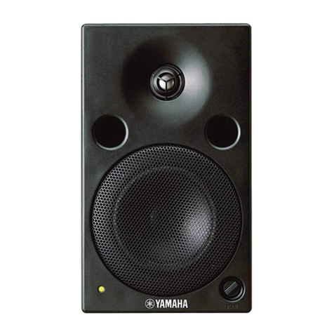
MSP5 MSP5
7
[A180C] [A180A]
[A190][A200]
[A180B]
[60]
4 PowerTransformer
4-1 Remove the woofer. (See procedure 1)
4-2 Remove the amplifier assembly. (See procedure 2)
4-3 Remove the three (3) screws marked [A150A] and
one (1) screw marked [A151A]. The power transformer
with the base can then be removed. (Fig. 4)
4-4 Remove the four (4) screws marked [A150B].
The power transformer can then be removed.
5 MAIN (1/5,2/5) Circuit Board
5-1 Remove the woofer. (See procedure 1)
5-2 Remove the amplifier assembly. (See procedure 2)
5-3 Remove the power transformer. (See procedure 4)
5-4 Remove the four (4) screw marked [A170] and the
two (2) screws marked [A160]. The MAIN (1/5,2/5)
circuit board can then be removed. (Fig.4)
6 MAIN 3/5 Circuit Board
6-1 Remove the woofer. (See procedure 1)
6-2 Remove the amplifier assembly. (See procedure 2)
6-3 Remove the four (4) screws marked [A180A]. The
shield sheet can then be removed. (Fig.5)
6-4 Remove the two (2) screws marked [A180B], the
nut marked [A190], the washer marked [A200] and
the screw marked [A180C]. The MAIN 3/5 circuit
board can then be removed. (Fig.5)
Fig.4 Fig.5 Fig.6 Fig.7 Fig.8
[A151]
[A150]
[A150]
[A150]
[A150]
[A151]
[A150A]
[A150A]
[A170]
[A160]
[A150B]
[A150A]
[A151A]
[A170]
[A150B]
[A150]: Bind Head Tapping Screw-B 4.0X10 MFZN2BL (EP600240)
[A151]: Bonding Tapping Screw-B 4.0X10 MFZN2Y (V2491300)
[A160]: Bind Head Screw 3.0X14 MFZN2BL (VH610100)
[A170]: Bind Head Screw 3.0X6 MFZN2BL (EG330360)
[A180]: Bonding Tapping Screw-B 3.0X10 MFZN2BL (VQ049800)
[A190]: Hexagonal Nut 12.0 14X2 MFZN2BL (VD794100)
[A200]: Flat Washer 12S MFC2BL (VB004700)
[140]: Bind Head Tapping Screw-P 3.5X8 ZMCBL (VD277800)
[A150]: Bind Head Tapping Screw-B 4.0X10 MFZN2BL (EP600240)
[A151]: Bonding Tapping Screw-B 4.0X10 MFZN2Y (V2491300)
7 MAIN 4/5 Circuit Board
7-1 Remove the woofer. (See procedure 1)
7-2 Remove the amplifier assembly. (See procedure 2)
7-3 Remove the knob marked [60] and the nut. The
MAIN 4/5 circuit board with the volume can then be
removed. (Fig.6)
8 MAIN 5/5 Circuit Board
8-1 Remove the woofer. (See procedure 1)
8-2 Remove the amplifier assembly. (See procedure 2)
8-3 Remove the two (2) marked [140]. The MAIN 5/5
circuit board can then be removed. (Fig.7)
9 Heat Sink
9-1 Remove the woofer. (See procedure 1)
9-2 Remove the amplifier assembly. (See procedure 2)
9-3 Remove the power transformer. (See procedure 4)
9-4 Remove the MAIN 1/5 circuit board.
(See procedure 5)
9-5 Remove the two (2) screws marked [A151] and
the eight (8) screws marked [A150]. The heat sink
can then be removed. (Fig.8)
w
w
w
.
x
i
a
o
y
u
1
6
3
.
c
o
m
Q
Q
3
7
6
3
1
5
1
5
0
9
9
2
8
9
4
2
9
8
T
E
L
1
3
9
4
2
2
9
6
5
1
3
9
9
2
8
9
4
2
9
8
0
5
1
5
1
3
6
7
3
Q
Q
TEL 13942296513 QQ 376315150 892498299
TEL 13942296513 QQ 376315150 892498299
http://www.xiaoyu163.com
http://www.xiaoyu163.com

